


vossiewulf
-
Posts
1,477 -
Joined
-
Last visited
Content Type
Profiles
Forums
Gallery
Events
Posts posted by vossiewulf
-
-
Johann, it seems like with the gunport lids having a hole in them that this corvette always stowed its guns outboard like that, instead of inboard with the gun muzzle against the bulkheads? When did they start doing that? Also, it seems to me if you're stowing the guns that way, you're putting a lot of faith in the tampions that they won't allow any water in with the muzzle exposed to rain and spray.
And the whole thing is extremely perfect. The gundeck would definitely pass the captain's inspection.
-
Jason sells holly strips at Crown Timberyard. I used them for my deck.
- mtaylor and vulcanbomber
-
 2
2
-
7 hours ago, Bob Cleek said:
I enjoy perusing the Micro-Mark catalogs and I have occasionally bought things from them when they have good sales, but I have found over the years that a lot of their tools aren't the best quality and are often priced substantially higher than elsewhere.
Oh, I agree wholeheartedly about Micro-Mark, most of the few tools I had from them were replaced long ago. But in this case, the set has been perfectly reasonable quality although I don't remember what I paid for it- I don't think it was $99. But I've gotten a lot of use from it and everything is still working fine. So if you can get the same thing cheaper, good deal.
- Canute, mtaylor and thibaultron
-
3
-
The only safer table saw is the Sawstop. And it's expensive, and you can't cut anything but fully seasoned wood on it without risking the wood's moisture tripping the electrical resistance detection mechanism for bits of human bumping into the blade. When that happens you have to buy a whole new safety mechanism as it's destroyed in stopping the blade near instantly.
And it doesn't stop kickbacks at all.
Real table saws are just damned dangerous devices and when they get up into multi HP you should have giant heaping heaploads of respect for the machine before trying to operate it. I always force myself (ditto with shaper/jointer/any serious machine) to take a deep breath and look around and confirm again I know what the hell I am about to do before turning on a table saw. I worked for 5 years building custom furniture and had more than a few close calls and bad events. I still have occasional nightmares about the time I was tapering a table leg and the wedge-shaped cutoff dropped into the tiny slot next to the blade and bent it toward the work, and suddenly I had a 5hp saw trying to throw the whole taper jig at my face and only my full weight on it was barely stopping that from happening, and I couldn't remove a hand to reach the emergency cutoff. I don't know how long it really lasted but to me it was a very long time before a guy on the other side of the shop recognized the sound of the saw binding and came running to shut it off for me.
- mtaylor, Canute and Roger Pellett
-
3
-
I recommend Castello Boxwood. It has a finer grain structure than any of your current options, and is easier to work than maple.
If you're stuck with those three, I'd recommend cherry as it could be left natural and will turn that nice cherry brown on its own, and is somewhat easier to work than maple.
-
I've had the Micro-Mark set for about 10 years and have used it fairly often on brass, but not often on steel. However they have worked fine for either material and have cut threads that fit even 0-80 quite smoothly. Unless they've changed their supplier, I would consider it a good purchase.
- mtaylor, Canute and thibaultron
-
3
-
When you reach a time where all your processes are perfected to the point that no further improvements can be made, you're no longer learning anything and it becomes just execution. That's where I start getting bored
")
-
Improperly kiln-dried wood (lumber yards will dry boards too fast) is the type of wood most likely to have stored internal stresses that will manifest as reaction wood, i.e. wood that visibly bends as it is ripped, frequently binding the saw blade being used. The other source of reaction wood are trees that grew on steep slopes, so one side of the trunk is under significant tension while the other side is under compression. That kind of reaction wood can have boards hugely sweeping as they are ripped.
If you've never had the wonderful opportunity to rip some reaction wood on a 5HP table saw, you've missed a chance to be at least scared to death, if not had that fear justified by having the whole board thrown back at you at high velocity. I had a case of the latter and have a nice scar on my hip as a result.
- CaptainSteve, Mark P, Canute and 2 others
-
5
-
-
15 hours ago, sjanicki said:
I also used an x-acto knife to cut the plates from their sheet. Definitely a learning experience!
The best way to cut those plates cleanly and this is also true of photoetched brass, is to cut them on glass. Get a small piece of 1/8 tempered glass with nicely rounded edges and it's a perfect surface for making those kinds of cuts. Also, both cutting the metal and running into glass is hard on Xacto edges and they're expensive, so the best thing to do cost-wise is to buy a nice cheap pack of 100 single-edged razor blades and use those for thin metal cutting.
-
1 hour ago, Marco R said:
I have tried to contact him 3 times but got no answer. Perhaps he is no longer trading. Any other ideas/suggestions anyone?
https://www.syrenshipmodelcompany.com/miniature-rope.php
It will cost more than shipping from Germany but it's excellent quality line, he's the only one I know who is likely to be able to fulfill your need.
-
24 minutes ago, Amalio said:
Secondly I would like to know if these stones that work with dry samples or with any element such as water or oil. I just ordered a 1000 grain, and I would like to know more about your experience.
Amalio, to use Shapton Glass stones, you just put a few drops of water on them, there is no need to soak them. Don't use oil, that would make them hard to clean. Use just a few drops of water and a few more along with a paper towel to clean them up when done.
You're also really going to like the speed at which they remove metal, it's very fast.
-
-
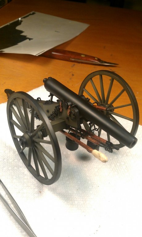
I did the 3 inch Ordnance Rifle in this series a few years ago, I was very frustrated with the poor surface quality of the white metal castings and replaced the cheeks and axle with my parts, and sanded/filed down all the surfaces of the wheels and trail and then re-engraved the wood pattern. Thankfully yours appear to be considerably better than what I received, but I still am baffled as to why they don't use resin with its far, far better castings surfaces.
-
1. Set the model on a flat surface and make sure the waterline is parallel to that surface.
2. Cut a block that is exact height of the waterline from the surface the ship is sitting on minus half the diameter of your pencil.
3. Tape said pencil to top of the block, and carefully draw the waterline with it all the way around the hull.
-
4 hours ago, BANYAN said:
That's looking very ship-shape Keith; I think the yard's master-shipwright would have considerable difficulty finding fault with that effort. The run of the planks looks spot-on so your planning and adjusting have served you well.
The part that's getting me is he's nearly done with planking a good solid 17 days or so since he started the entire build. I wish I could go that fast. Keith, please slow down, the rest of us are feeling inadequate
- John Allen and FriedClams
-
2
-
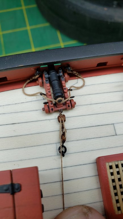
Sorry Pat thought I had already responded but left it in the editor- I considered removing the rings but it wouldn't have bought enough space to return the beckets and eyes, that's where I was saying something is generally amiss here as there just fundamentally isn't enough room. My understanding of the recoiled/loading position was that the muzzle of the gun was inboard, but here we have less distance between the end of the carriage and the ring than the length of the carriage itself, which means there's no way the muzzle of the gun is going to be inboard after firing and securing with the train tackle. So either the carriages and guns are too big for this ship or the rings need to be considerably nearer the deck center line. And that wouldn't work on one of the guns that's backed up by a big grate.
So I've gone with the simpler rig, not to say that they're simple to make now, it's still brain surgery but doing so has made it look at least vaguely like those tackles could have been used to do something.
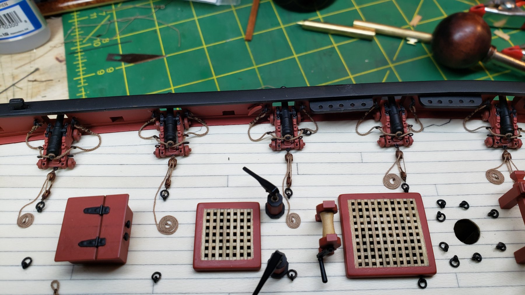
For anyone intending to build Lady Nelson, had I to do it over, I'd move the big grate more toward the stern to clear the one gun it interferes with, move the windlass to the other side of the grate, and move all the train tackle eyebolts much closer to the center of the deck.
I'm not making an effort to make the coils perfect and in the same place, my intent is to have it look not like it's ready for inspection but cleared for action.
Speaking of that, shouldn't there have been... I've forgotten what they're called but the trays for cannon shot someplace? Admittedly you can carry a 3 pounder round in one hand but I would still think there should be some ready supply on deck somewhere.

-
How were those frames stored? Fully seasoned or kiln dried castello boxwood shouldn't do that unless stressed.
-
27 minutes ago, rpeteru said:
Er vossiewulf I do not think the Japanese attacked Darwin in 1904 maybe 1942. The port you should refer to is Port Arthur, i think that was the name of the Russian base on the peninsula.
Yep you're right, I meant Port Arthur, the night time destroyer attack on the Russian fleet.
-
14 hours ago, paulsutcliffe said:
mole grips
13 hours ago, KeithAug said:mole grips
That's a new one on me, I've never known them as anything but vise grips here. Very handy whatever they're called.
- FriedClams, mtaylor, KeithAug and 1 other
-
4
-
Only thing ThreeDecks has is La Fontaine d'Or, a 24 gun privateer launched in 1676 and sunk in action in 1677.
- mtaylor and Louie da fly
-
2
-
Jolene, I would take about a 1" wide file to both of those problems, that size file's thickness is about the right size for the bulkhead slots also. You don't have to be super perfect on the slot, you can hold or clamp the bulkhead in the correct place and pin it with CA glue, then fill in any spaces with more CA. If you don't yet have some files, buy some, you need from about 1" wide down to fairly small in size, as for shapes, flat ones and round ones at least. No you don't have to answer me individually, build your ship.
- src, popeye the sailor, mtaylor and 1 other
-
4
-
Since she was one of a kind, couldn't it be a unique rig if you haven't been able to find anything else using it?
- thibaultron, BANYAN, mtaylor and 2 others
-
5
-
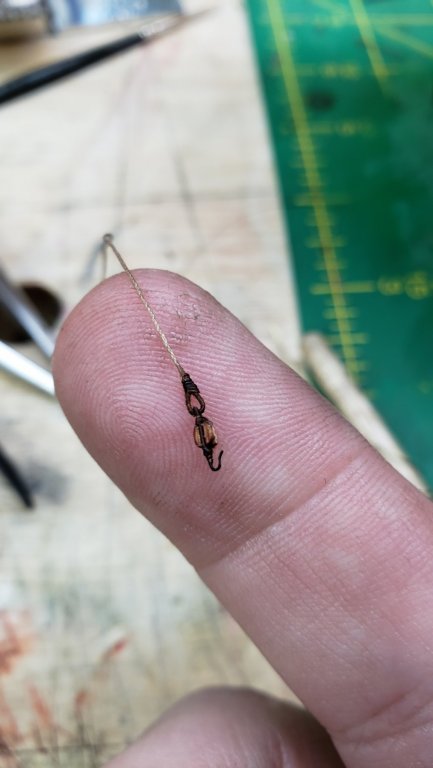
So as you see it looks like I have to give up the becket and the eye on the line and just seize the line directly to the single block, but it will work. It's distressing that I have to make significant compromises on the accuracy of the rigging; unlike with airplanes where I know based on scale what I can and can't do, I really don't know what you can get away with at what scales in ships.
It's also distressing as that means you can't do really good rigging below 1/48, and 1/48 is monstrously big models. Well at least you can't do really good rigging without making yourself a range of specialized super-miniature tools, which I may have to do.
Even so, with the nice blocks and line from @Chuck and the right size fly line, the tackles will still look nice and of course only a tiny minority of the people who will look at it will have any idea that anything is missing. It was originally @src's suggestion to eliminate the eyes and beckets but @BANYAN twisted my arm into giving it a try. You're both right, you have to be an eagle-eyed ship modeler to see that things have been simplified and the deck will look much better with the train tackles in place, thanks
- KARAVOKIRIS, rafine, hexnut and 11 others
-
14


[BEGINNER] Schooner Vega: help me read these plans
in Building, Framing, Planking and plating a ships hull and deck
Posted
You don't really need to glue them at all against the bulkheads, just edge glue one to the next. If you feel you have to glue them, just tack them- use as little glue as possible in one spot which will make it easy to pull the bulkhead piece off later without damage.
And this is a standard convention with plank on bulkhead ships, the upper parts of the bulkheads are just temporary forms for the bulkhead planking. Which itself will then probably be planked a second time from the inside.