
.JPG.ca33079f5815b861e67b9c2cccd37982.JPG)

Blue Ensign
-
Posts
4,287 -
Joined
-
Last visited
Content Type
Profiles
Forums
Gallery
Events
Posts posted by Blue Ensign
-
-
Easy for you to say James, I'm scratching my head as how to proceed.🤔
B.E.
- Dave_E, hollowneck and mtaylor
-
 3
3
-
Post One hundred and sixty-three.
Final touches.
With the boats put aside it’s back to looking at what is left to do on Sphinx.
I turn my attention to the Hammock Cranes, sorting and prepping the individual parts.
I find myself puzzled by the Quarterdeck cranes.
There is scant mention of these, a brief comment on p102 of the manual, referring to fitting them later, but nothing follows.
.jpeg.2afab72de1297a03fd918c53380ccb84.jpeg)
Prototype build.
I note that James dodged the bullet in the prototype build, they are missing from the final completion photos.
The cranes are identified on Plan sheet 11, Suppl. drawings 7. (PE93 – 103 R&L)
The cranes are handed, and specific to each location. This presents issues when the items are to be chemically blackened because each set ideally has to be kept separate, and there are eleven sets.
They can’t therefore be batch blackened, and the cleaning and blackening will have to be done on a set basis to avoid mixing them up.
.thumb.JPG.aecf67299e388f81cd61155a998a2e53.JPG)
8510(2)
Each crane consists of two parts, the crane, and a tiny base plate into which it fits. presumably up to the nub on the shaft
How it fits is not immediately clear and it looks like the base plate needs drilling out to allow passage of the crane thro’ to the hull.
The secondary question is whether it is better to glue the plate to the hull first, then drill and fit the crane, or attach plate and crane first, and then fit to the hull.
CA is probably required to glue these fitting, which raises the concern of how to fit these without marring the blackened surfaces.
I rather feel that a brief explanation of this fitting and a couple of supplementary photos would have helped in this area.
B.E.
24/09/2022
- DelF, mtaylor, realworkingsailor and 4 others
-
7
-
An interesting project and conversion Kevin, she's going to look magnificent when completed, the lighting will make her very special.
B.E.
- chris watton, Canute, mtaylor and 2 others
-
5
-
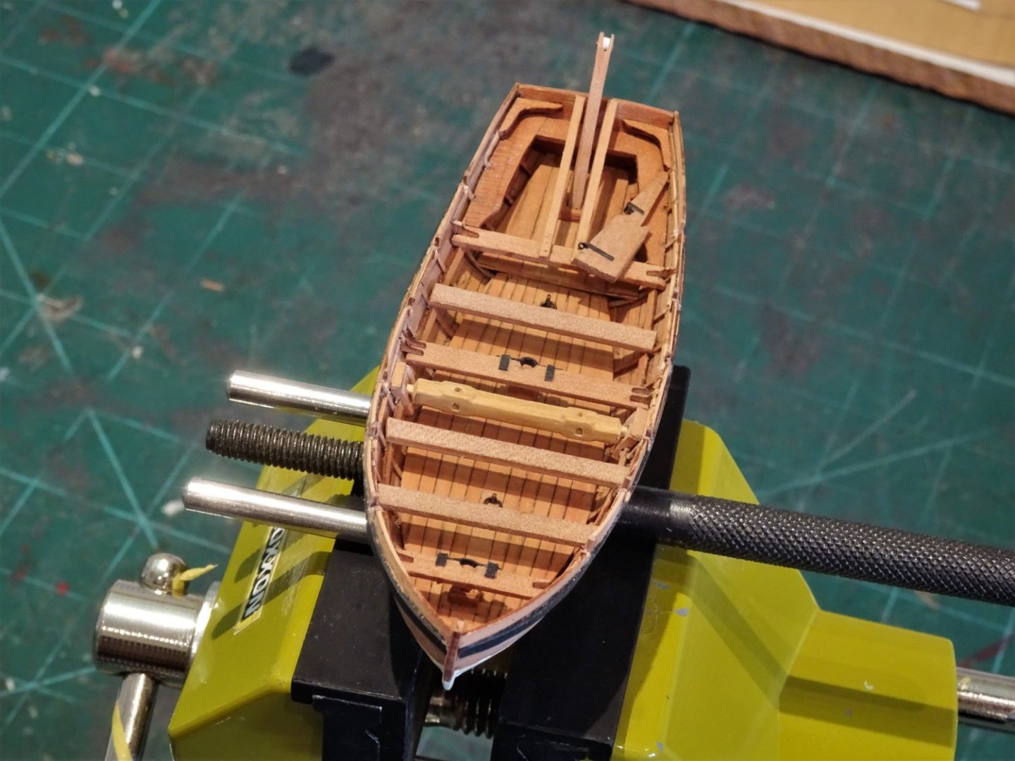
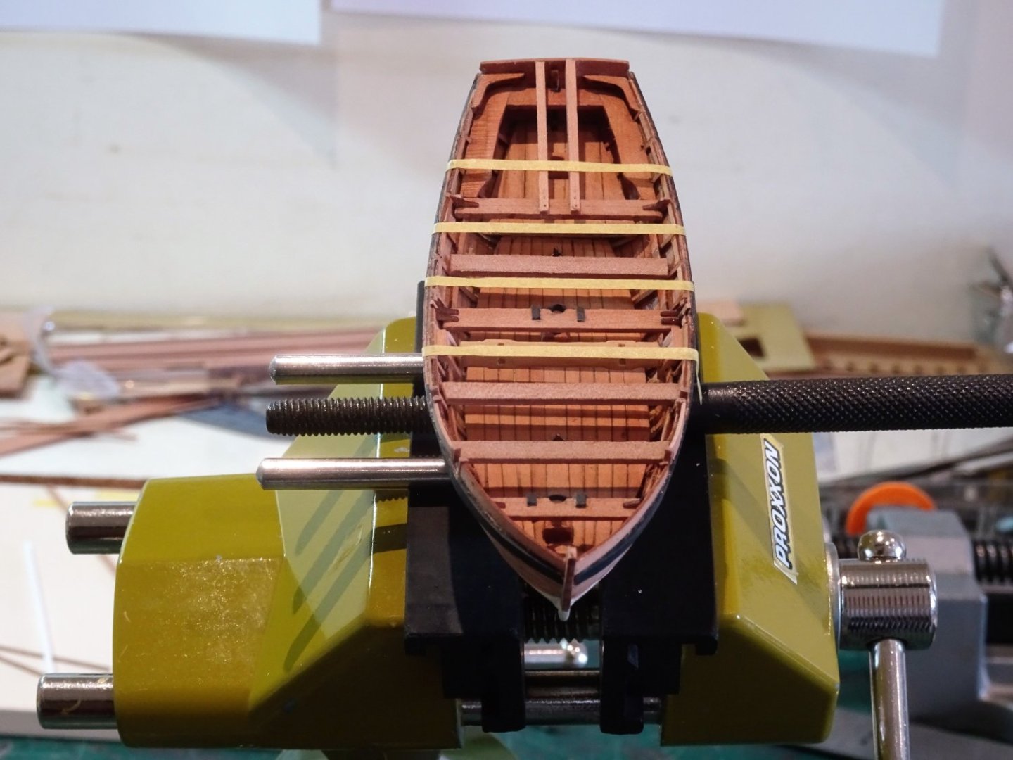
Post One hundred and Sixty-two.
Completing the Yawl
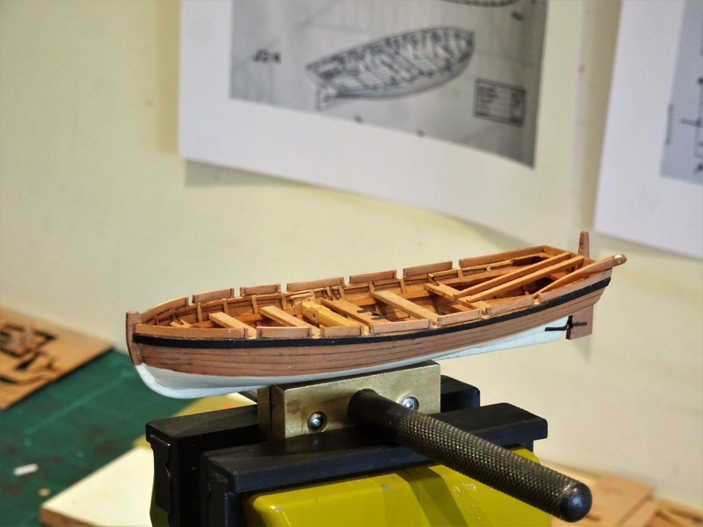
The third of the allocated boats for Sphinx, it’s nice to come back to it with all the planking having been done previously.
.thumb.JPG.c042948959a52622a73ff9521564f54c.JPG)
00620(2)
I have built this model before but on that version, I rigged her for sail. The Sphinx version is set up for rowing but will be tweaked a little to reflect the layout in the Pandora book drawings.
I won’t bore everyone with blow-by-blow details of the construction I covered this in the log below.
However, having thought that the Yawl would prove to be the easiest of the three to build, having done it before, it has turned out to be the most problematic.
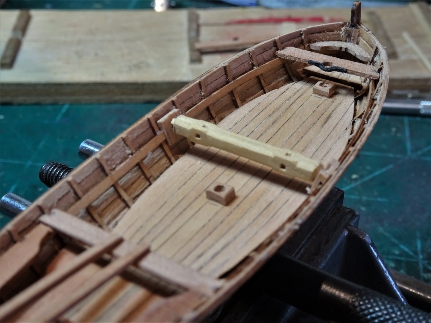
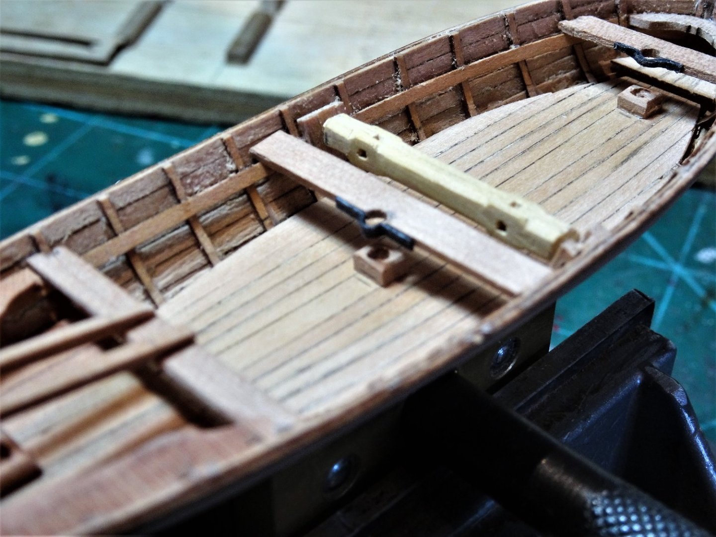
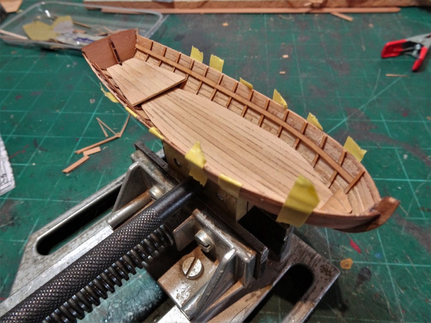
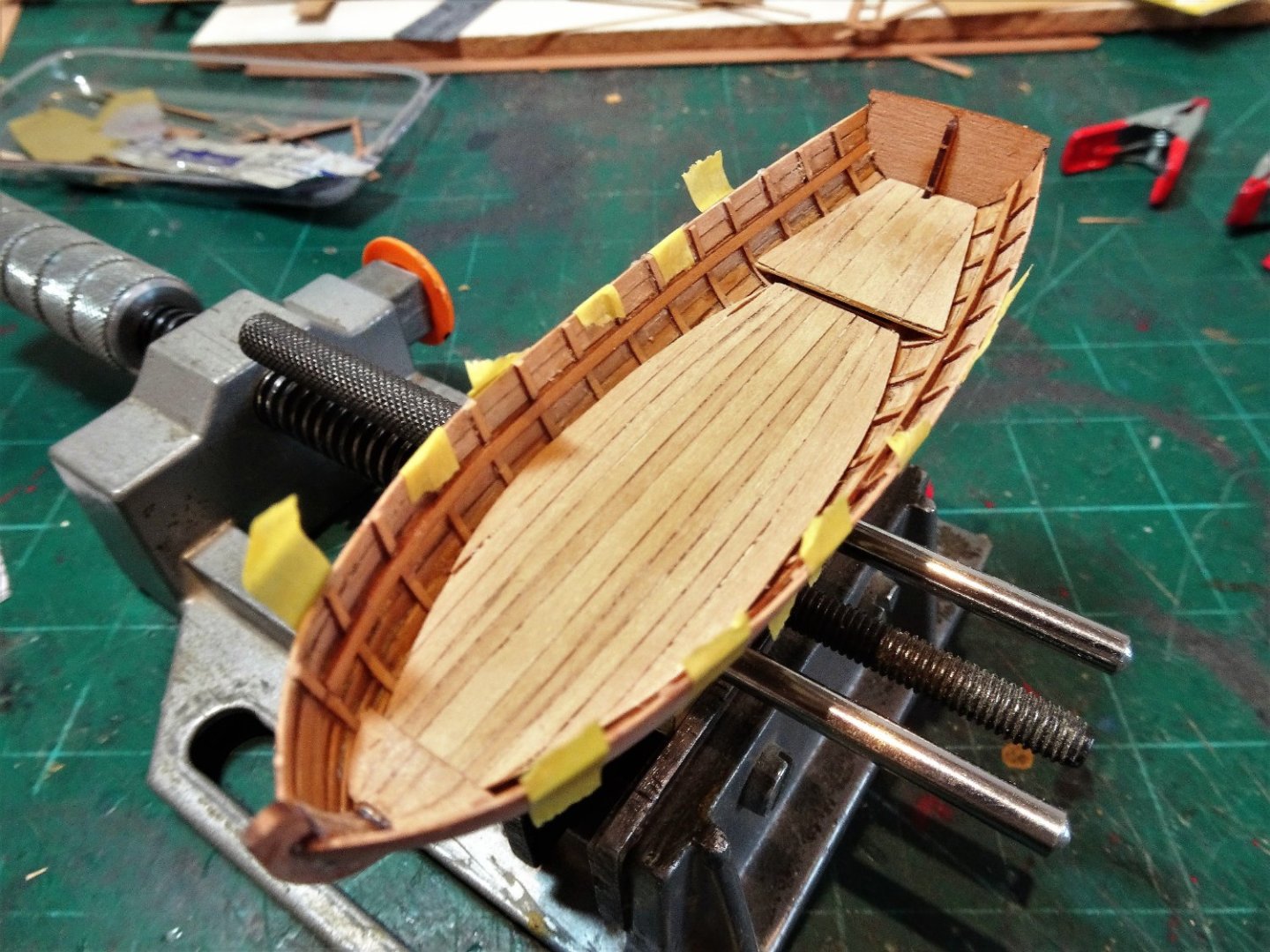
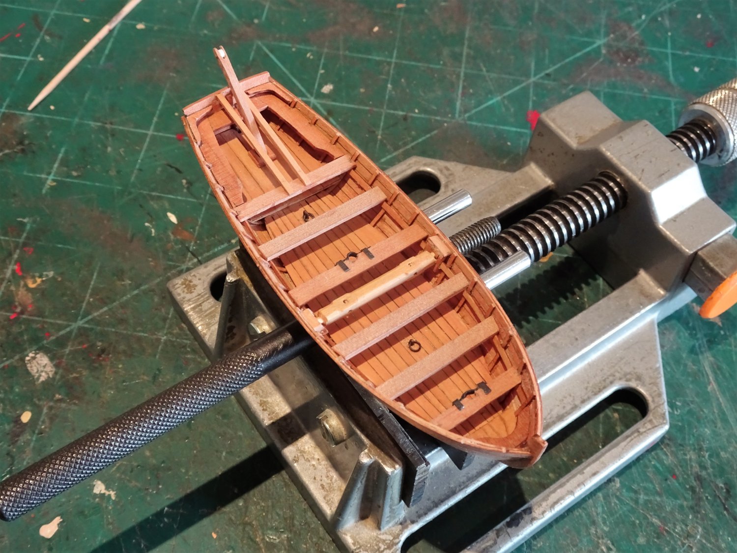
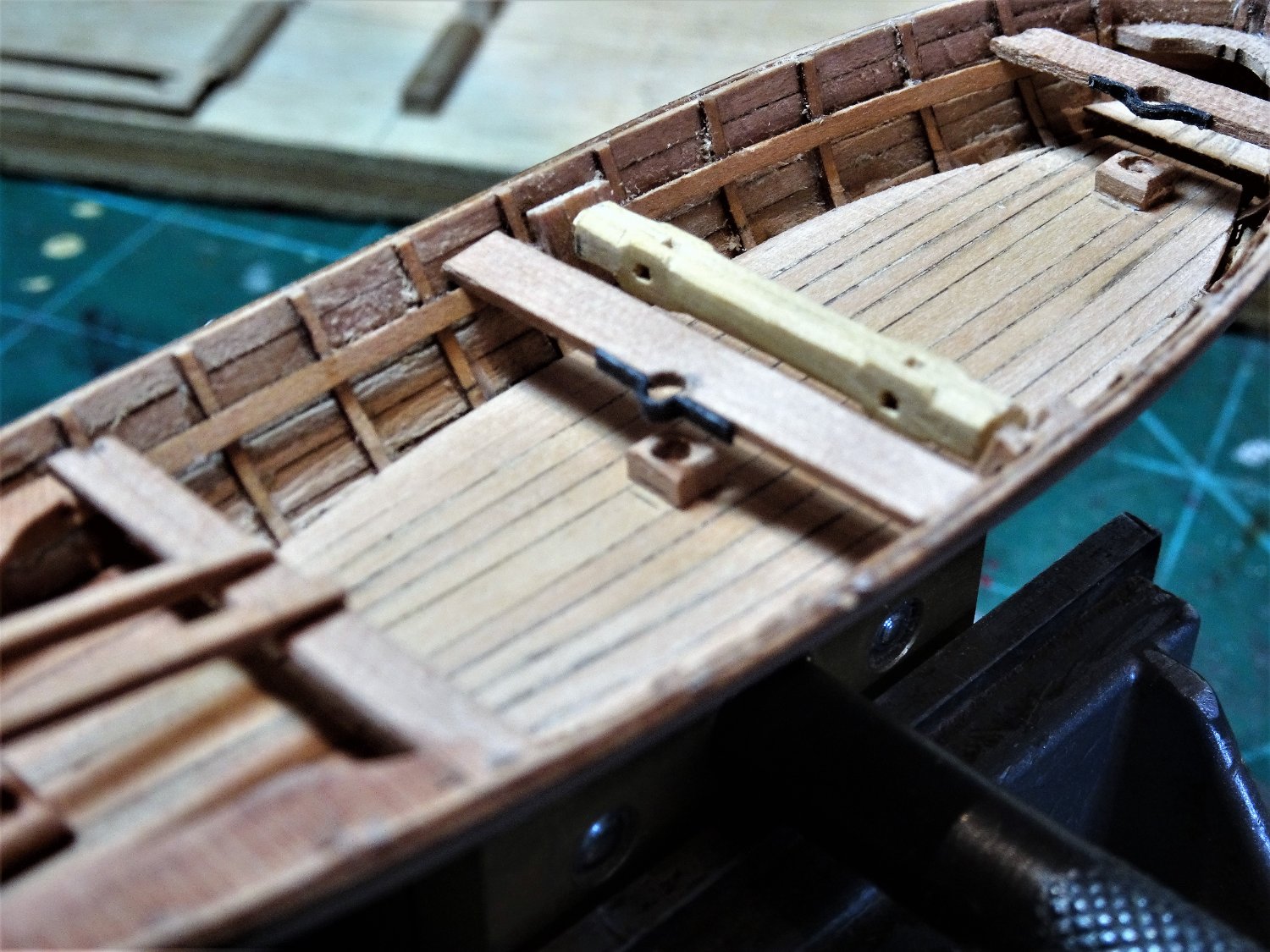
I wasn’t happy with the fit if the sternsheets, so I decided to scratch a replacement.
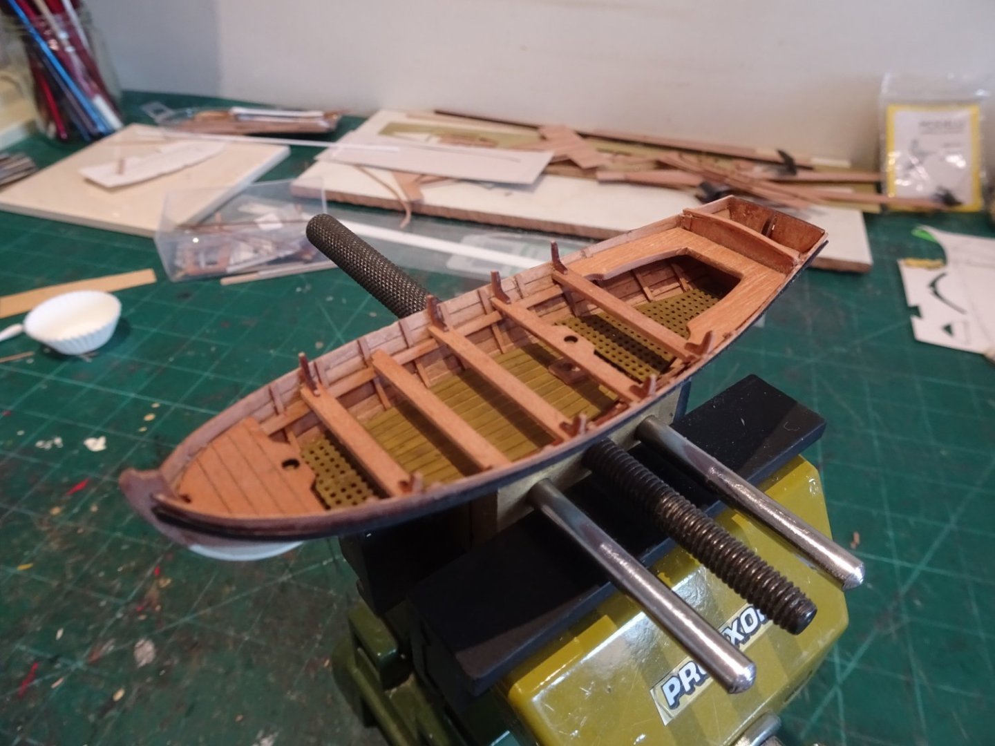
8287
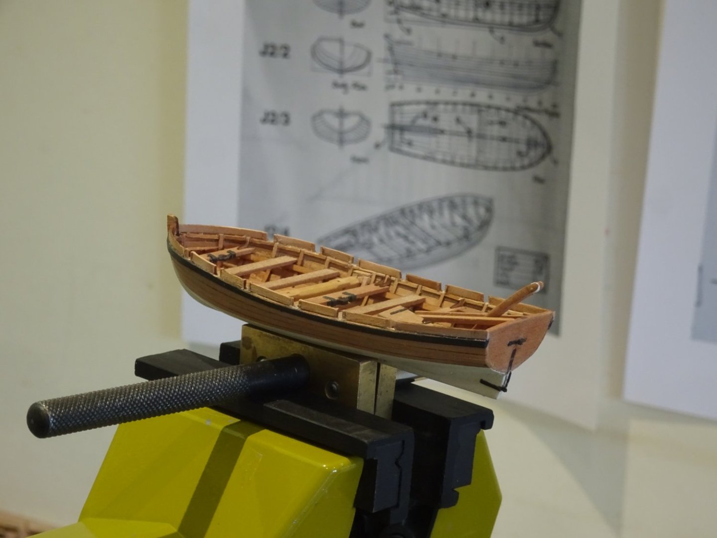
Despite the fact that Lavery notes:
The Yawl was unusual in that it was decked throughout its length, in three stages.
I opted to use the provided brass etch decking and grating, altho' it did mean drilling thro’ the decking plate to attach the lifting rings.
As with my first Yawl build, I reduced the foredeck by removal of the board adjacent to the mast support.
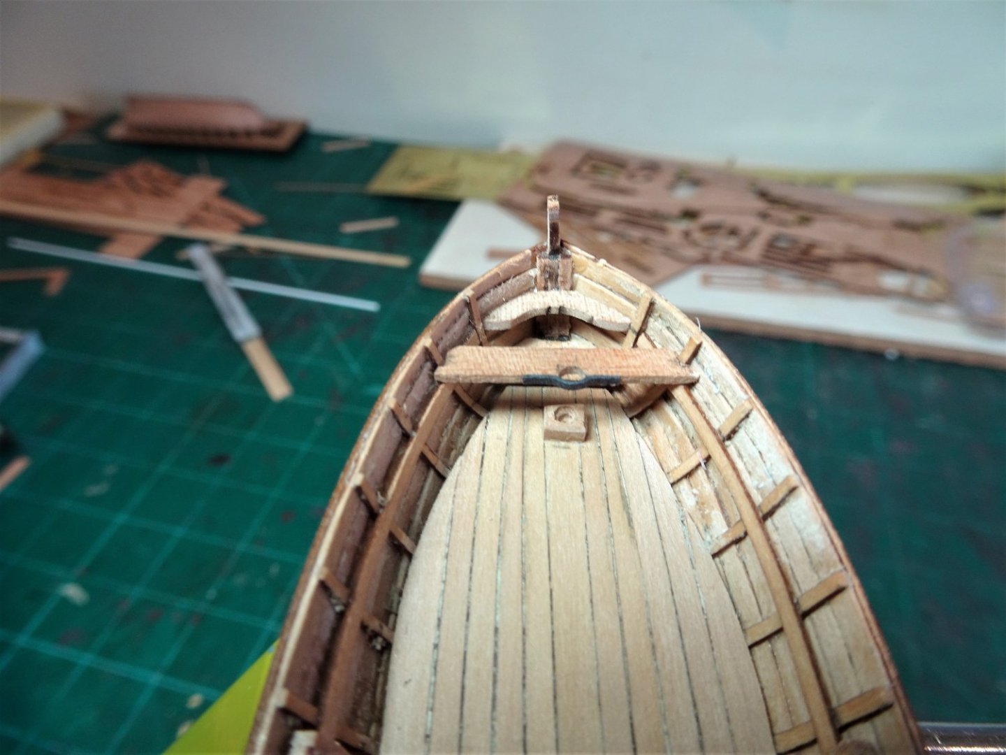
.thumb.JPG.053574eac7e6e32a942fb7677b741e51.JPG)
8482(2)
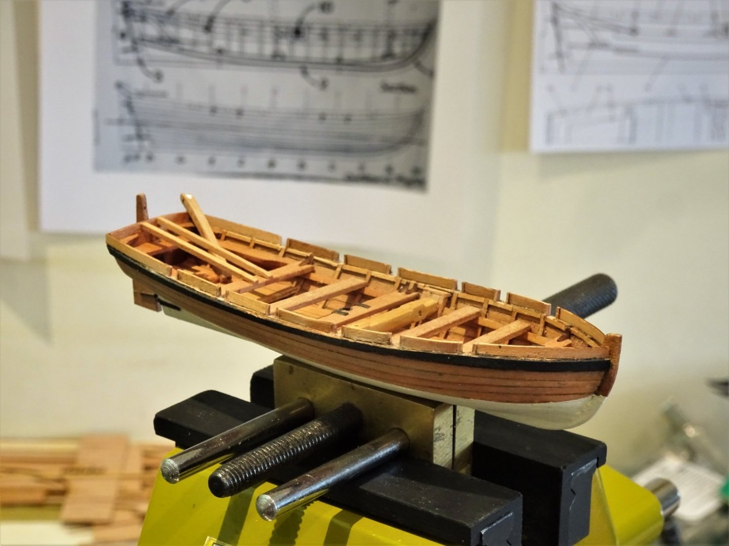
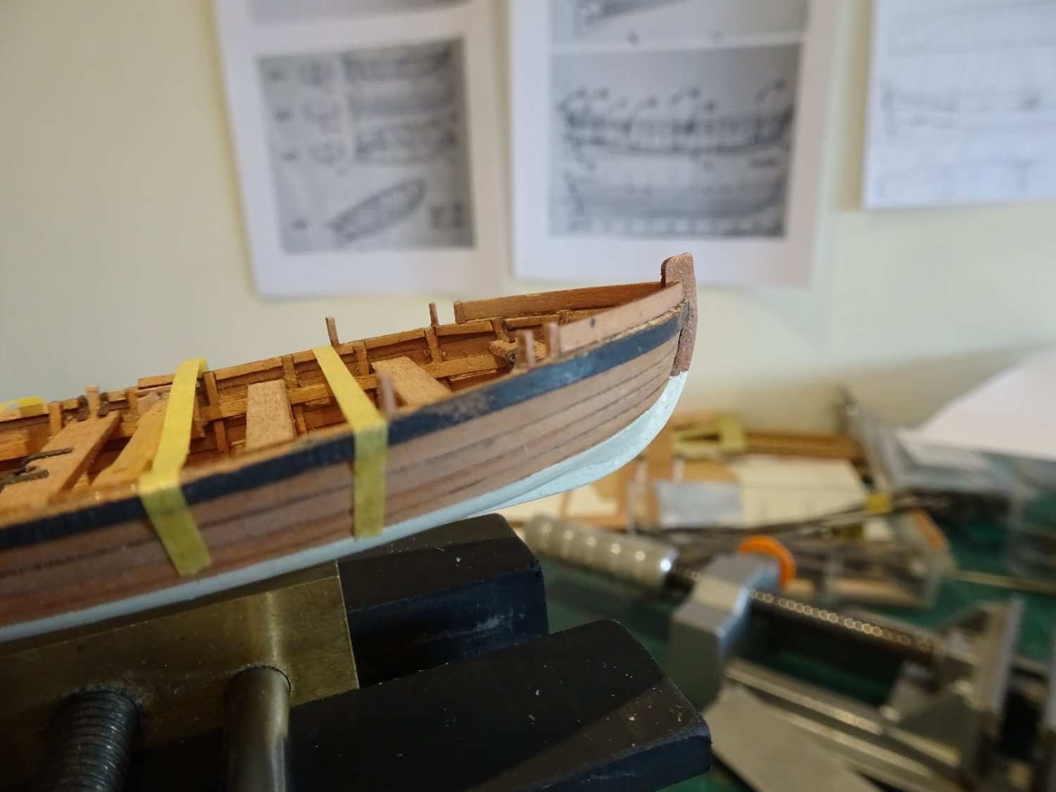
With the Yawl I opted to use the kit non-operational rudder assembly, except I did not use the brass etch facings, preferring to laminate the core with 0.6mm Pearwood.
The strapping was formed using laser board strip.
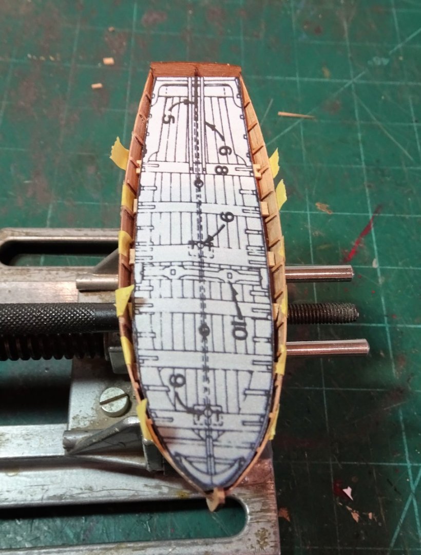
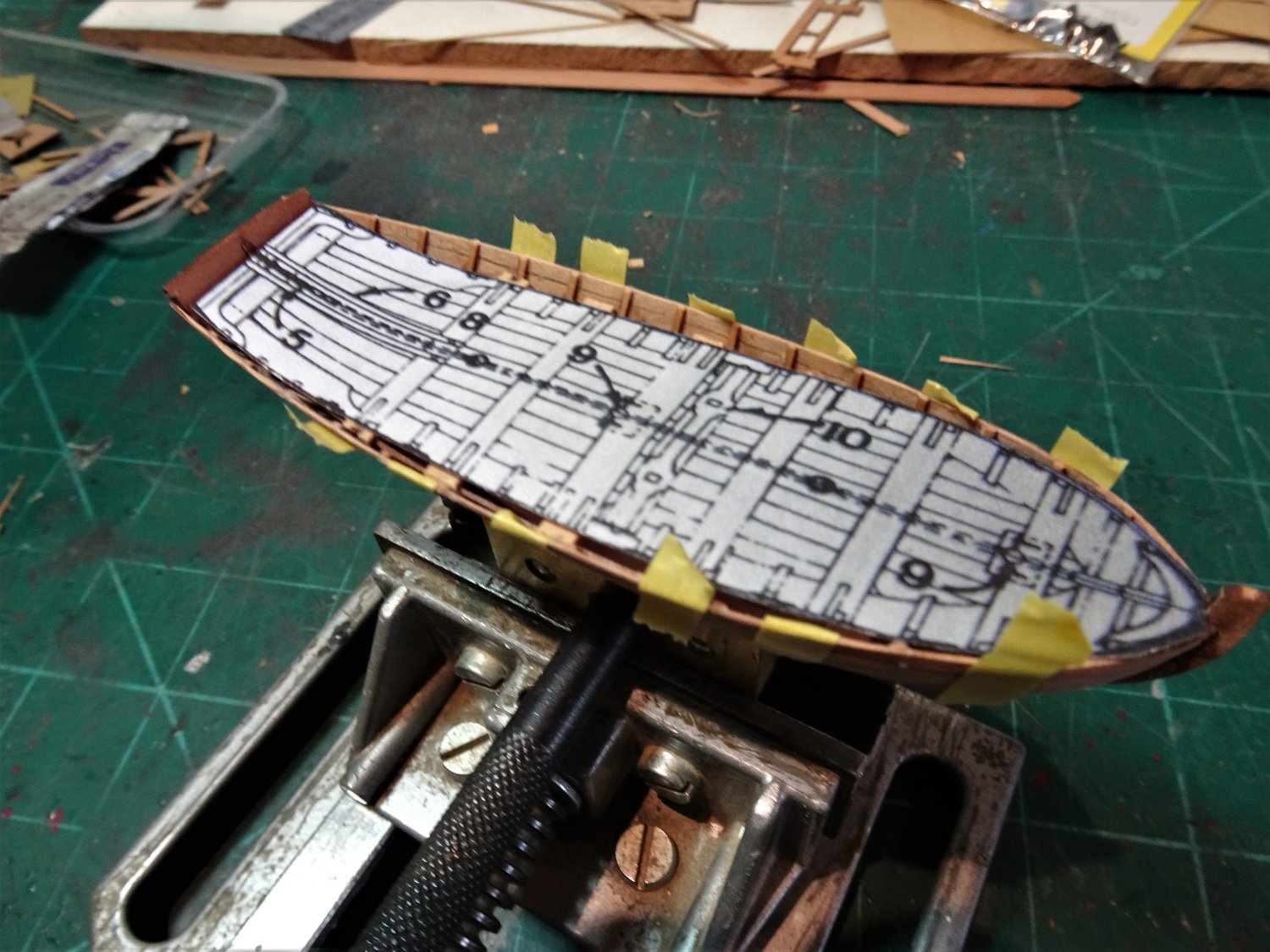
.thumb.jpg.298f59b60c4b9568a316cf7e1bf29a58.jpg)
3814(2)
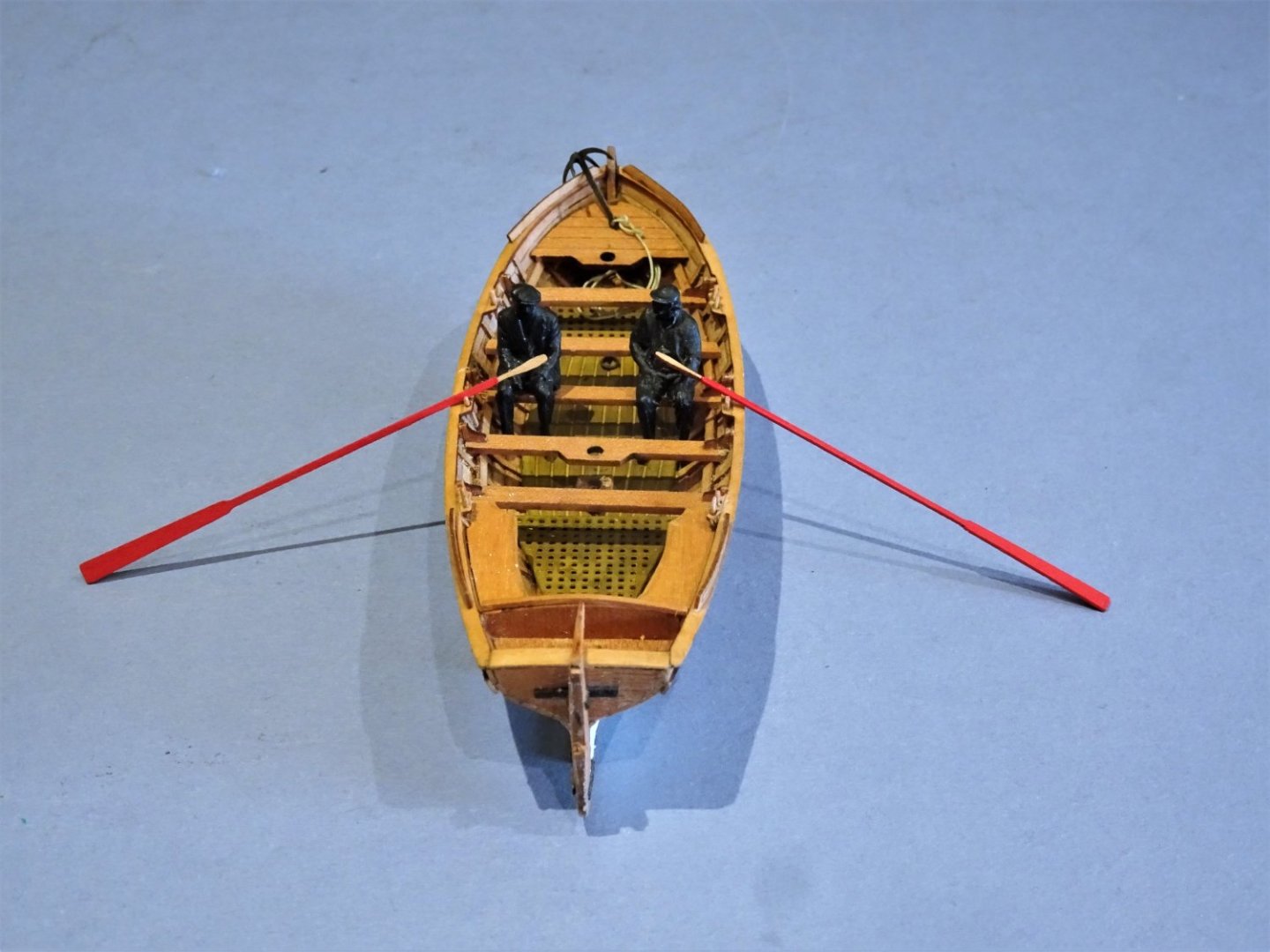
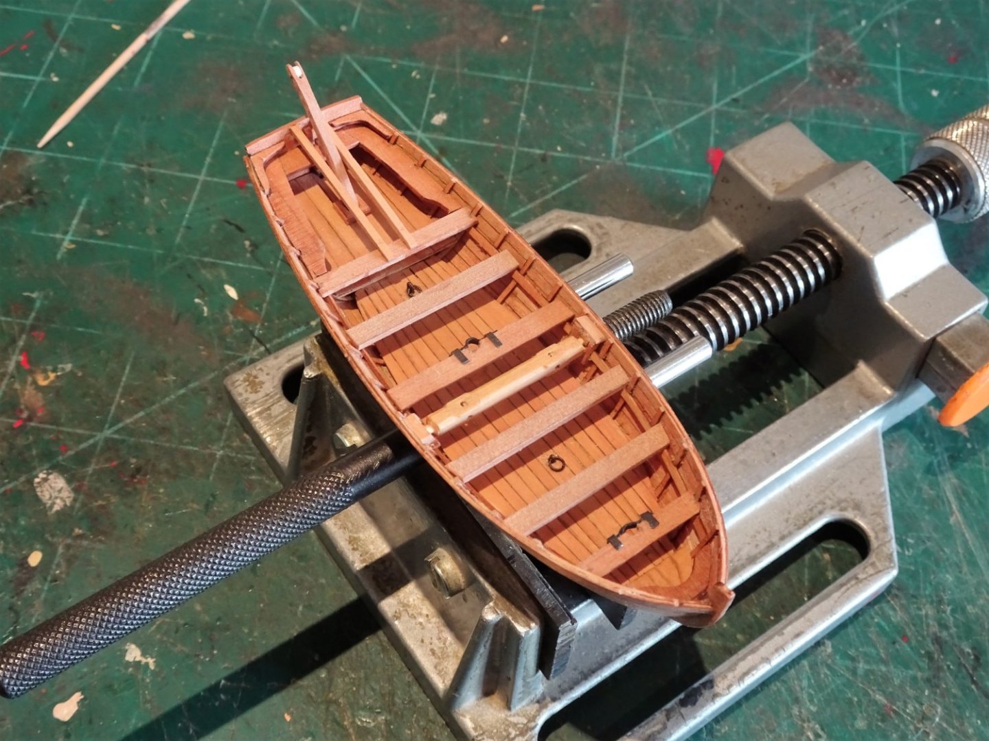
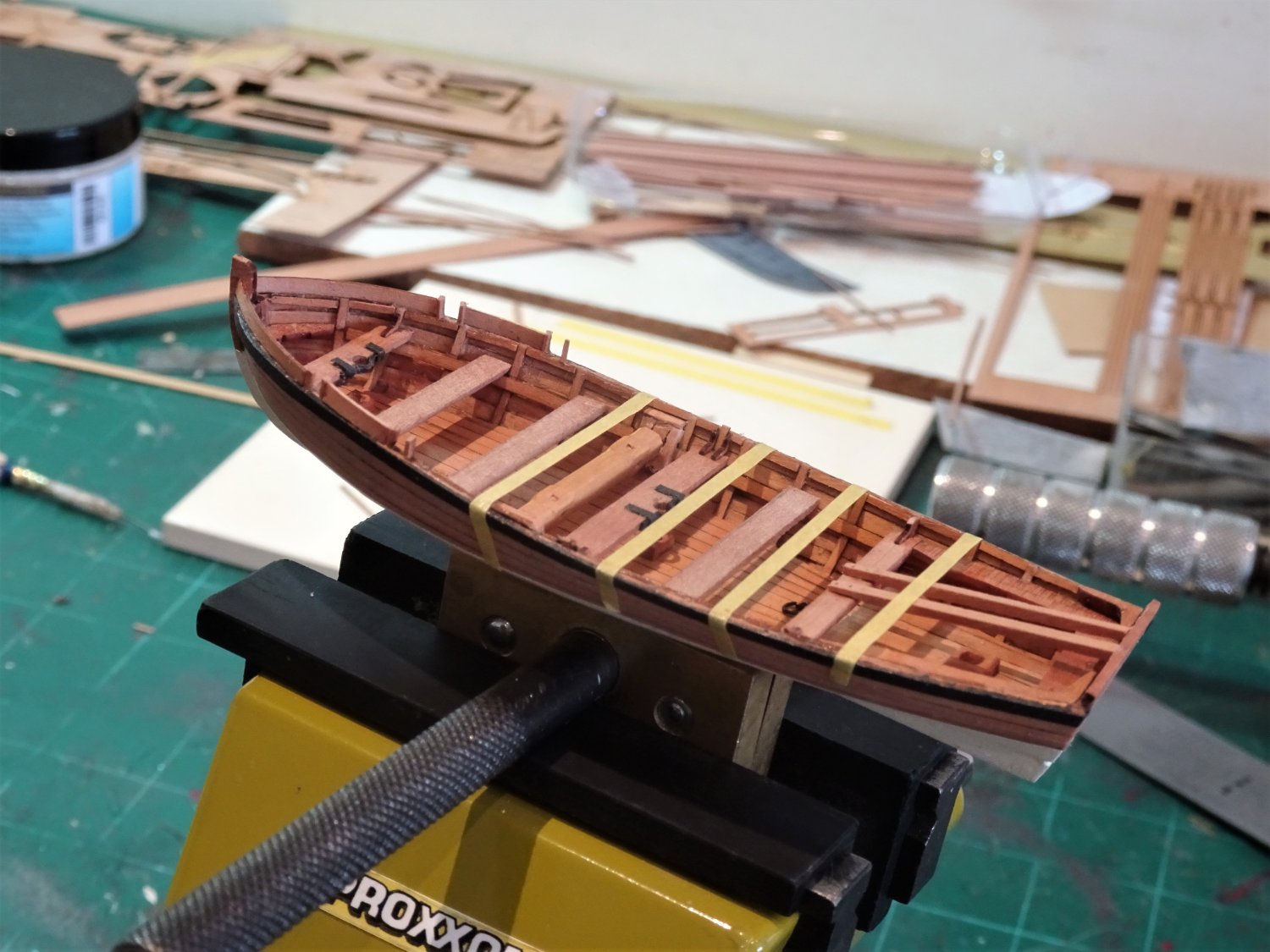
This Yawl plan from the NMM (ZAZ7122) is set up for six oars which is right for the size and does show tholes set up each side on alternative thwarts.
Does the plan indicate that there would be corresponding tholes on the starboard side of the hull? This would suggest that she is set up for double banking, but single banking would also work with this layout with tholes on the alternative thwarts.
I have left the kit arrangement as is- set up for six oar double banking.
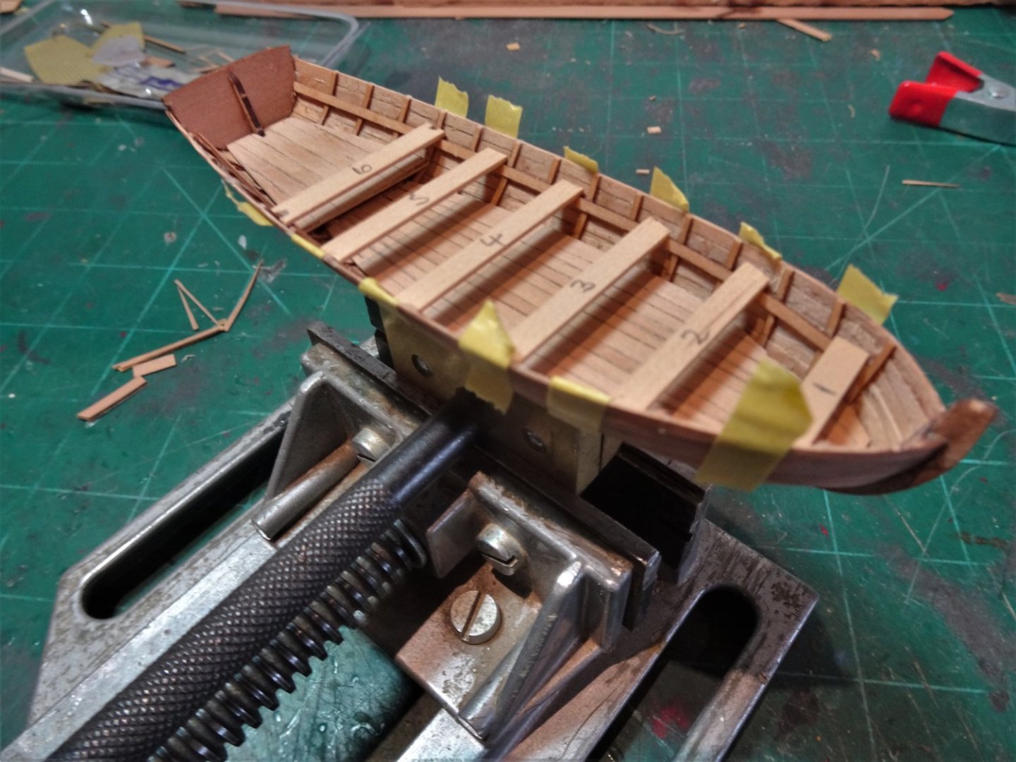
.thumb.JPG.94746e155ff186ecc5c8d3d458a19993.JPG)
8465(2)
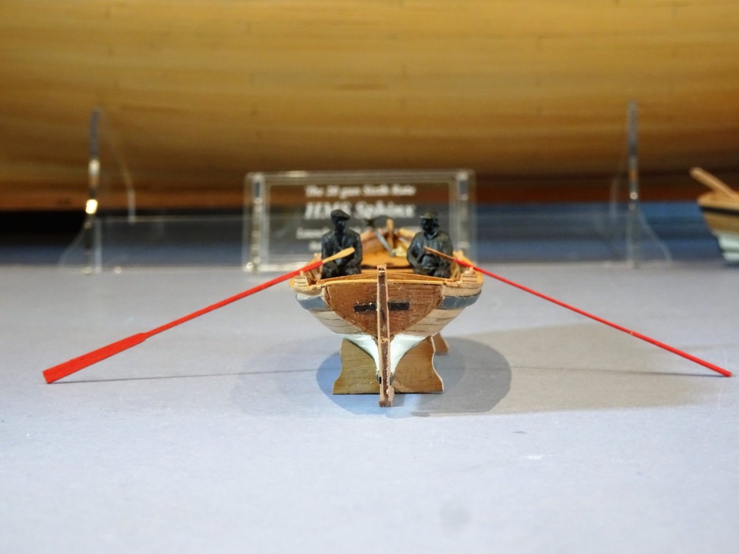
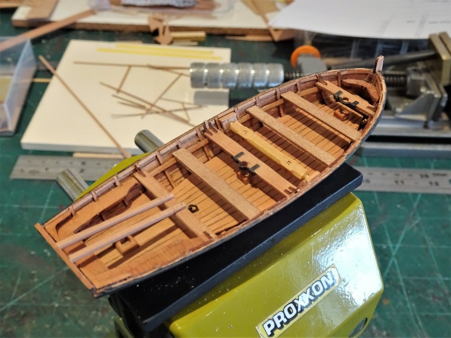
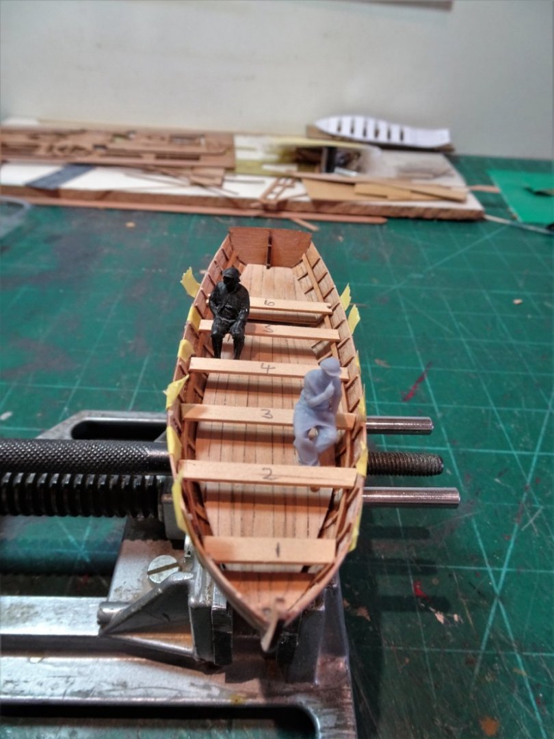
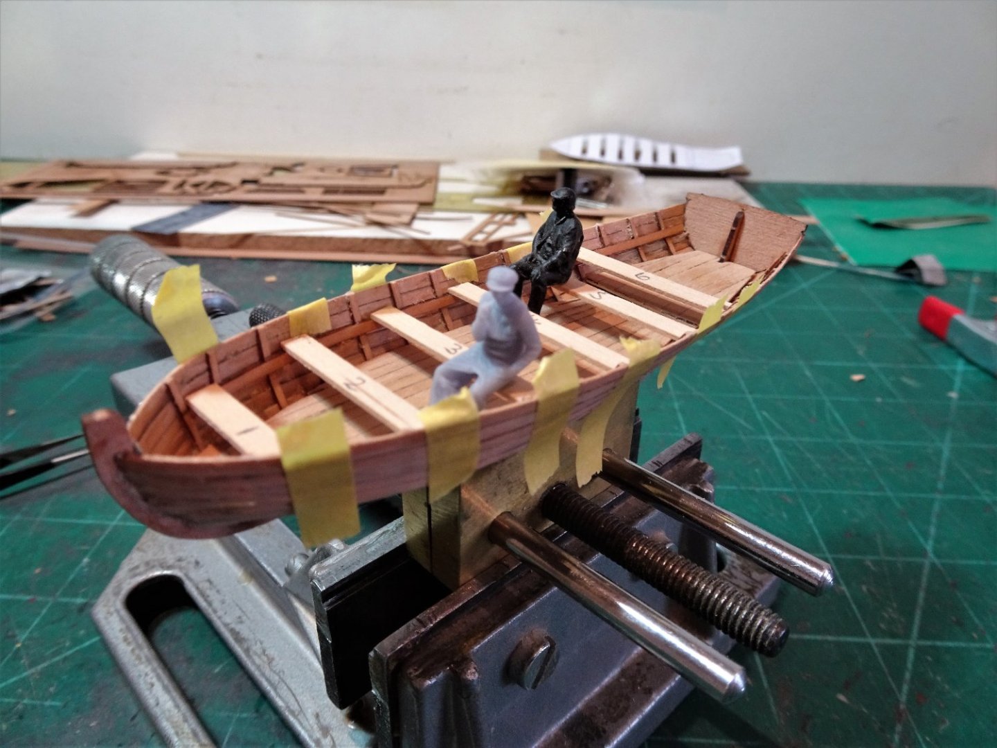
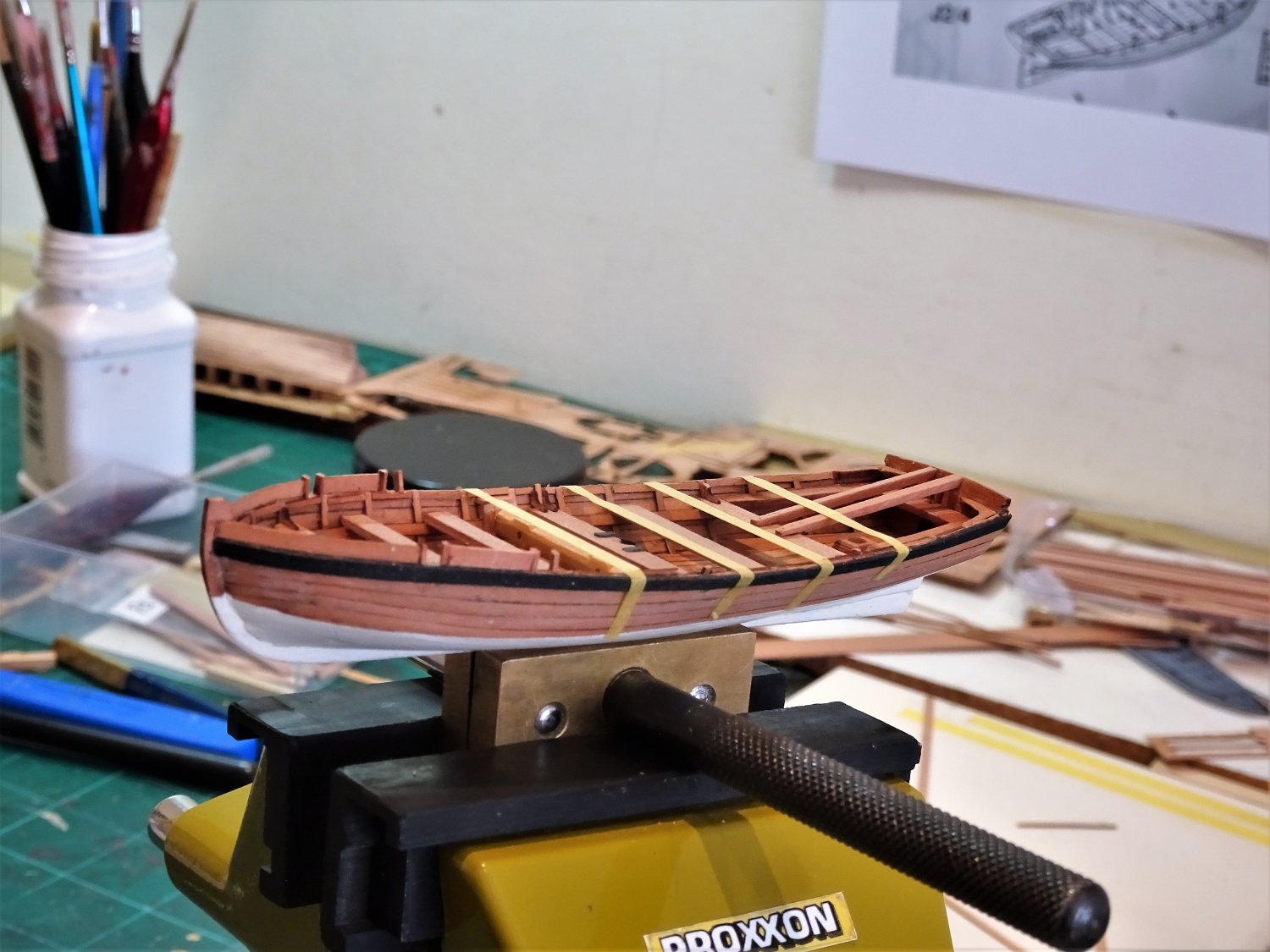
I couldn’t resist seeing how two burly fishing boat skippers would fair sitting double banked on the narrowest thwart.
8501
and at midships, with a space of 5’ 9”
It seems to work at 1:64 scale, but enough of this playing around.
.thumb.JPG.92ad58cdab526aebfdddf27c55ae37d5.JPG)
8484(2)
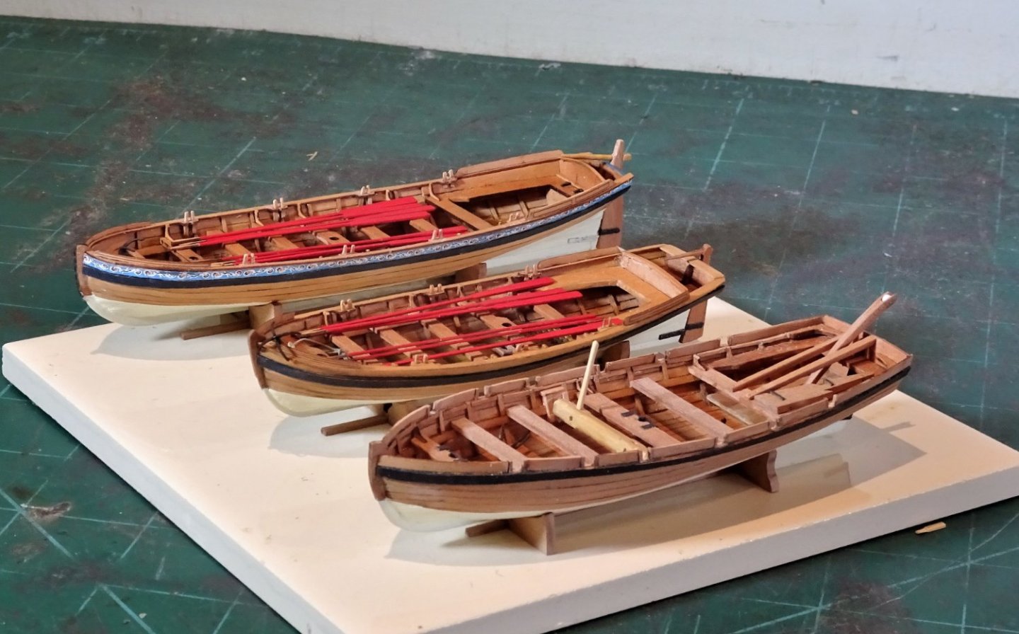
I used the provided Pearwood oars with the char removed, and with a very limited round applied to the shafts. These are delicate pieces, and the handles particularly will break very easily.
At this scale there is very little option to model the swelling of the looms without working the shafts using separate 1mm Boxwood square stuff, something I was not prepared to do for the number involved over the three boats.
I opted to paint the oars red as a contrast to the bright finish of the boats.
8502(2)
.thumb.JPG.3f938461fd2ecdea87a84e8919afba5d.JPG)
8506(2)
The kit also provides very pretty little grapnels. These were silver soldered together before chemical blackening.
.thumb.JPG.156066e63ff12d5ddd342234f514dfb2.JPG)
8481(2)
8476(2)
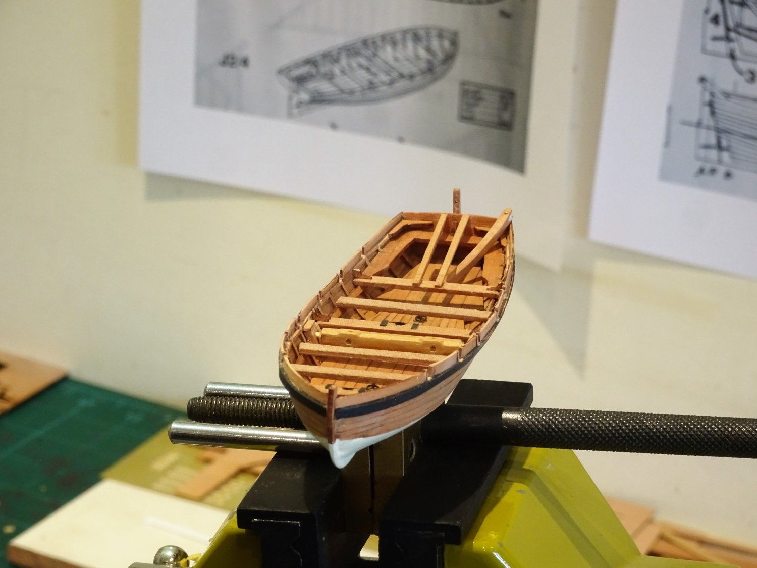
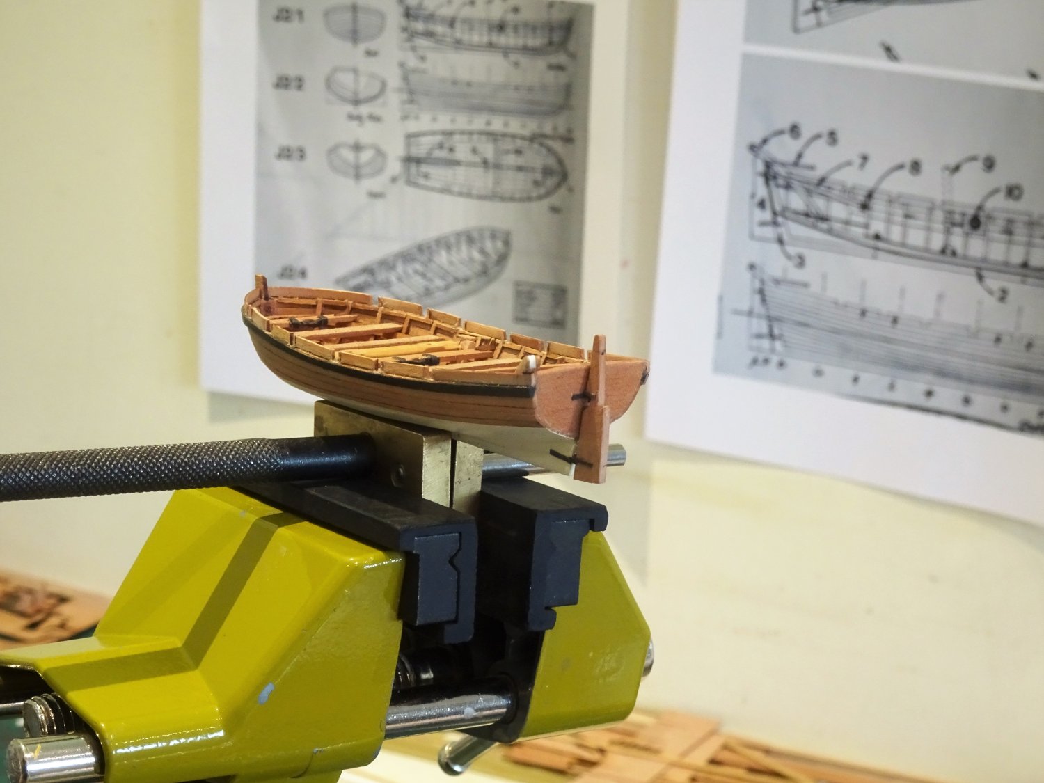
The completed set: has taken a fair amount of time to complete the boats, but it’s time I don’t begrudge, they are interesting little projects in their own right.
.thumb.JPG.d13afb0f3ca0aece4dcb920cfc350902.JPG)
8488(2)
Fully convinced that Sphinx looks better without boats onboard.
.thumb.JPG.dea7d134a54d462f025472991fac1386.JPG)
8499(2)
.thumb.JPG.8181b664055dc4a0a071b429c066f2e4.JPG)
8495(2)
I will now return to Sphinx to attend to the final finishings.
B.E.
22/09/2022
-
Looking great James, would have loved those lodging knees for Sphinx, would have saved me a whole load of cutting out.
Ah well.
B.E.
- chris watton, thibaultron, Dave_E and 2 others
-
5
-
Hello Haiko, I’m pleased that you are finding my log of use.
The main yard served as an example of my approach to the fitting and stropping of the blocks used on the yards, but there are differences both in the numbers and sizes of blocks used on the Topsail and T’gallant yards, and you go thro’ the log you will see that I have detailed the blocks used by size and type as I attend to each of the other yards.
I didn’t use the kit rigging plans, my rigging was based on Steel’s rigging tables, and the excellent Volume IV of The Fully Framed Model, Rigging a sixth rate sloop of 1767- 1780 by David Antscherl.
Regards,
B.E.
- Mirabell61 and Keith Black
-
2
-
In the days before the internet and MSW, each edition eagerly anticipated.🙂
B.E.
- allanyed, chris watton, druxey and 6 others
-
9
-
Nice collection Chris, remarkable similarity to my own library, even down to the old Model shipwright editions.
Even now I can’t resist adding to the pile and your fishing boat kits have created a whole new category😊
B.E
- chris watton, mtaylor, KentM and 4 others
-
7
-
Looks good James, realistic finish, I like it. 👍
drip tray a nice addition, I recall I had to make one for Sphinx.
B.E.
- AJohnson, hollowneck, thibaultron and 4 others
-
7
-
Thanks Guy's, for your supportive comments, much appreciated.👍
I'll be fiddling with Sphinx for a while yet when I get back from the Lakes.
Whether to fit the Hammock cranes or not is one thing on my mind as I look out of the window at Hartsop Dodd, thoughts of model making rarely go away completely.🙄
B.E.
-
For the past couple of weeks, I have been busily trying to complete the Yawl, which is now all but done.
Sphinx is now back in her case whilst we decamp to the Lake District for a spot of hill walking.
.thumb.JPG.25d4ab16992d60b84173d6c9b8957948.JPG)
8315(2)
.thumb.JPG.e3871feafc06aa93f844140c4083761f.JPG)
8327(2)
Deciding how I will display the completed model is something occupying my thoughts.
B.E.
09/09/2022
-
She’s looking great Doug, a fine clean job you’re doing.
As far as the head tapering is concerned, Allan is correct in that the head did taper from top to bottom, but as far as the kit is concerned such adjustments may affect the other kit designed features, such as fit of a figurehead, and other features around the headworks. In my humble opinion best left alone unless you’re planning a modification early in a kit build, lest the outcome looks not as good as the original.
B.E.
-
Nice result Rusty, a fine model.👍
B.E.
- hollowneck and Rustyj
-
2
-
I just love the sweep of your hull timbers up to the the lower counter, and I think you were right to remove the first go at the counter frieze.
I too am a fan of Chuck's paper friezes and they look so good on Winnie, I adapted them for Sphinx.
Beautiful work Glenn.
B.E.
- Dave_E, glbarlow, FrankWouts and 2 others
-
5
-
According to Brian Lavery (Arming and Fitting) skid beams were standard by 1750, initially with iron crutches to secure them, but he indicates that their use on Ships of the line became more permanent by the 1780's.
His comments regarding frigates which is more relevant to Winchelsea is that; Frigates were rather slower in adopting gangways and boat booms and do not appear to have them until the early 1800s.
I think Chuck's approach of spare topmasts to support a ships boat feels more appropriate, and more aesthetically pleasing in relation to 'Winnie' of 1764.
B.E.
- Rustyj, scrubbyj427 and KentM
-
3
-
Post One hundred and Sixty-one.
The Launch – completion
8258
Busy, busy, in the workshop, a case of spot the the boat.
8264
With the wash-boards attached a fair bit of cleaning up is required, but overall I am satisfied that the modification was worth it.

8265
The Rudder
The final addition; as with the other boats I put the kit arrangement aside in favour of a working rudder using the typical long pintle at the lower end.
.thumb.JPG.b46b441bf1ac9ea63e66ceb678d27e73.JPG)
8254(2)
The long pintle is silver soldered using a fine brass eyebolt and pin.
.thumb.JPG.1d655d9b68cd0b9a0a657efe0ae0ffd5.JPG)
8255(2)
A brass micro tubing sleeve is used to give support where it fits into the lower stern post.
8266
The long pintle is particularly important in relation to the Launch as to work the Davit the rudder would need to be removed quickly and easily.

8260
8262
If the rudder is shown in place, then the Davit is stored in the Stern-sheets.
8270
If the Davit is shown in place, then the Rudder is not fitted, it would be taken onboard.
.thumb.JPG.f2f122a103f16a99de78ad38b8263c47.JPG)
8274(2)
For display purposes I will have the Davit in place as it is a launch specific fitting.
.thumb.JPG.a80faa0edc3c76cef6eec2a350f8f431.JPG)
8276(2)
With ten days labour I think I’ve had my moneys worth out of the Launch kit, a lot of modifications in one small hull.
.thumb.JPG.45907c557863bbdc9e80cb40a3fbeb99.JPG)
8279(2)
Two down, one to go.
B.E.
29/08/2022
- BobG, PhillH, jpalmer1970 and 24 others
-
27
-
-
Post One hundred and Sixty.
The Launch – ongoing
Detailing continues; the thwarts are in place along with the Windlass. The lifting rings have been added to the keelson.
8220
Still to add the thwart brackets.
Fitting the brackets is an exercise in frustration; they are incredibly tiny items, seemingly smaller than those for either the Pinnace or Yawl.
The only saving grace is that brackets are required for only three of the thwarts, which allows a margin for the inevitable escapees.
Before I move onto the wash strakes I needed to decide whether to paint the bottom of the launch up to the waterline.
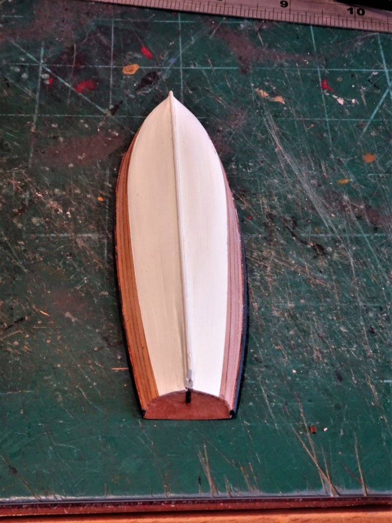
8221
I had intended to leave the whole hull bright across the range, but I quite liked the effect on the Pinnace, so ivory bottom it is.
On the kit the hull is painted white overall up to the wale, but I prefer a bright hull between waterline and wale which provides a nice contrast.
Wash-strakes
These are formed using planking strips allowing for the oarlock spaces.
The blurb says add more lengths of planking along the bulwark top for the oar positions.
Easy to say, not so easy perhaps to achieve.
There is nothing to support these thin strips and they should follow uniformly the curve of the hull.
The kit arrangement is a simplification, presumably due to scale. In reality there would be tholes to secure and take the pressure of the oars, and against which the temporary wash boards would be secured.
8224
To try and add a tad more realism to the set up I fitted strips between the frames along the inner hull to support the tholes.
Admittedly I am doing this as an exercise to see if I can, and it does extend the build time which means I don’t have to think about another one.🙄
The thole positions are marked and the process can begin.

8234
The wash strakes at the Bow are attended to first, these are heat treated to follow the hull before fitting against the first thole.

8244
With that done the next thole can be fitted with a 1.25mm spacing, and so on.

8241
8250
I will continue to fit the wash boards and hope it all turns out ok. The danger will be when I come to clean it all up, whether these delicate pieces will hold in place.
B.E.
27/08/2022
- gjdale, dunnock, fake johnbull and 10 others
-
13
-
Post One hundred and fifty-nine.
The Windlass
This is a tricky fitting to make, the actual length of the Windlass is a mere 28.4mm which has to contain both square and octagonal sections.
Steel records the Windlass for a 24’ Launch as being of 8”ø which equates to 3.2mm at scale.
I will be using 3mm Boxwood Square stock for the makings.
How to begin.
When in doubt refer to Chuck;
Chapter four of his Medway Longboat Monograph explains the process and fortunately I have his wonderful Medway Longboat at ½” scale, and in the plans is a template for making a windlass.
.thumb.JPG.f2cb06c6c8e0ea71dc8a676bd2295a1e.JPG)
8184(2)
Reduced to 1:64 scale it provides a guide that should prove very useful, provided my eyesight is up to the job.
I have made windlasses at 1:48 and 1:64 scales previously but that was some years ago.
The templates are glued to the faces of the square stock and it’s then down to how well the octagons can be formed.
.thumb.JPG.66a61fde9750ae9c3dad91bf9dba49e7.JPG)
8186(2)
The stock is supported in a simple ‘V’ jig.
.thumb.JPG.b11f763e36e56f723bc6e12c5a412536.JPG)
8187(2)
I use No11 scalpel blades and micro chisels to form the octagons.
.thumb.JPG.3892433e31cd8c9d553efd6aa9c8429c.JPG)
8190(2)
I use the No11 scalpel blade to form the rebate.
.thumb.JPG.72ed9cb0efadc9a308c5c756afd023b0.JPG)
8195(2)
The template certainly simplifies shaping the windlass particularly at this scale, as marking with pencil lines is not so easy on this small area.
With the template removed a little more definition is given the the octagonal areas, and the ends formed.
8198
Trial fitting of the windlass into the support chocks.
8201
The Main Thwart is checked against the Windlass position.
The remaining thwarts can now be made and put into place.
A final thought, given that the windlass is an important feature of both Longboats and Launches, I think a resin version of the Windlass would be a good ‘optional’ fitting for the Vanguard Launch kit.
B.E.
25/08/2022
-
-
Post One hundred and fifty-nine.
The Launch – cont’d
Fitting the stern sheets
The kit provided part includes the stern-sheets and adjacent thwart as one unit. There is no bench on the aft side against the transom.
.jpg.15e8759b6a3c27627c1fb1bac7158e36.jpg)
Victory Launch - note the dis-mounted Davit
This may be a design feature to allow easier fitting, which it does, but I am aware that the current launch with HMS Victory also has no transom bench.
I chose to include a Transom bench between the two side benches, as per the drawings in the AotS books, Pandora and Diana.
.thumb.JPG.5cc8f85e1ad3e0a83ab63ef4b87775cc.JPG)
8173(2)
The individual seating parts were split up and the cut-away shape common in side benches, was formed.
The Davit
The kit provided Davit is of a simplified form lacking the sheave in the outer end. I also thought it looked a little under weight.
The Davit was used to support the handling of anchors I doubled up on the kit pattern to create a sheave in the outer end, this gave an overall width of 2mm.
.thumb.JPG.314913811a1a58f0eb6dbc1e8dddc1b6.JPG)
8177(3)
The Davit supports were re-made using 1.5mm square stuff,
I also re-made the thwart adjacent to the stern-sheets, onto which the Davit supports are bolted.
8168
The Breasthook is fitted at the bow along with the first thwart. The remainder will be left until the Windlass is fitted.
I made the Fore mast clamp on the thwart with black card rather than use the provided etch.
.thumb.JPG.6ca1e0375ed08c96affad859a3d6b92f.JPG)
8170(2)
This is also an opportune time to add the wales which further strengthen the hull for handling.
More work is required cleaning up the inner hull, these macro shot fill me with horror.😬
I prefer scraping with a wetted sharp blade rather than sanding, the thinness of the planking always has to be borne in mind.
.thumb.JPG.134680060242da8cd9566259e6087ede.JPG)
8177(2)
The mast steps have been fitted and the Main Thwart made. This is wider by an inch than the other thwarts at 10” (4mm)
Before moving on, there is a windlass to make, an interesting little exercise.
B.E.
24/08/2022
- gjdale, Kevin, Mirabell61 and 16 others
-
19
-
I like the round pedestal table Chris, any thoughts of creating a seated figure to grace it?
B.E.
- Canute, chris watton, Nirvana and 4 others
-
7
-
Post One hundred and fifty-eight.
Building the Launch
This is the heavy work boat of the set.
Lacking the elegance of the Pinnace it does have interest to commend it and I’m looking forward to having a go.
The kit includes a simplified davit and its supports, but for some reason is lacking the windlass which is the other important feature of Launches, as it was with the Longboat.
I compared the kit launch with the drawings in the Pandora book for a 24’ Launch.
The book drawing does indicate the windlass and has two less thwarts (including the stern sheet ) compared to the kit version.

8107
The stage after fitting the ribs provides the first opportunity for revision.
The kit provides a brass etch version of the keelson and footwaling which I thought was perfect for replacement with a more authentic boarding.
The kit also provides brass etch gratings for the stern-sheet and bow areas.
Looking at Launch plans and those for Longboats, gratings did not seem to feature on these boats, and it makes sense that the stern-sheet footwaling was solid to form a stable base for the Davit step.
8110
Replacement footwaling, which at least saves me the trouble of trying to turn brass into wood.
8109
The Keelson is a slightly wider and thicker board that runs down the centre of the footwaling to support the mast steps and lifting rings.
The number of thwarts in the kit version is eight including the the one adjoining the stern-sheets.

8119
I am using the design for a 24’ launch in the AotS book Pandora.
8120
I will be using six thwarts which allows for a slightly wider main thwart at midships, and provides room for the windlass.
8111
With the stringers in place temporary thwarts are used to get things ship-shape.
8114
Once again my dockyard figures ensure the thwarts sit level and at the correct height, don’t want their feet dangling in mid-air.
8118
I still get a satisfaction seeing tiny feet planted on the footwaling, all down to Chris’s excellent scaling of the boats.
Still a fair bit of fettlin’ to do and a Windlass to make.
B.E.
22/08/2022
- fake johnbull, allanyed, Dave_E and 12 others
-
15
-
It's certainly not elitist to advance knowledge of our subject.
I accept the limitations of kits, they have to appeal to a large range of potential buyers, don’t frighten the novices, or unduly lack credibility with the experienced, whilst maintaining a reasonable cost/benefit ratio of producing the kits.
Chris does wonderfully well to authentically represent the majority of the subject detail, but it was the tweakability of Sphinx that appealed to me.
I record the modifications and changes I make in my builds partly on the basis that not everyone has access to the very large reference library I have built up over the years, and giving such detail gives options.
Of course many people just want to complete a nice looking kit, and that’s just fine.
Unlike myself not everyone has or wants a head stuffed full of 18th c trivia such as:
Worm and parcel with the lay, turn and serve the other way.
Mrs W definitely thinks I’m weird, but she indulges me in what in the overall scheme of things is a minority
interestpassion.Movin’ on
B.E.
- allanyed, Rik Thistle, Nipper and 5 others
-
8
.JPG.7ae330169ba72ab8ce58b8d0dc3c1a99.JPG)
.JPG.da9b3ad36a840667d96320fc080bfe5c.JPG)

.JPG.a6ade7519517651b076d335dbed31750.JPG)
.jpg.77ae408e6999b1f4f99650e38dc865e2.jpg)
.JPG.d9031c98532176efebd6a49df5435aa2.JPG)

.JPG.d32b48ad2dc0ca639c8f87526c78015a.JPG)

.JPG.42971ad0d1144de3d45271c1ddb3185e.JPG)
.JPG.4b86cd13cdbe815f671aaa4ab48d3537.JPG)

.JPG.e28b8fe59c10e65e7a77dbda550bc307.JPG)
.JPG.d7137b0d414ac63dad7b83ebdebec8c9.JPG)
.JPG.974e1bae632b1d962107ad41e16bb461.JPG)

.JPG.78495aff7f5f9a694f6466851c1517ad.JPG)
.JPG.8c070d6b730130c8e5b0b7b71adbd197.JPG)


.JPG.7296ffb049e2f0539de751e6daee16a0.JPG)
.JPG.e54dbbf76c130460b42d88093e0ab985.JPG)


.JPG.67823d626fb67a84a3645e5f3b588f68.JPG)
.JPG.6d75458cd0cd4d0275f69b340b5fd336.JPG)
.JPG.1061d1d4bcd957a5ef125f776168f4c1.JPG)


.JPG.862d4346879c070c85d268f2840972cb.JPG)
.JPG.edcafc7730866ff66e481136741601ad.JPG)
.JPG.d063cb4553e149c899befa22ff605c97.JPG)
.JPG.4c52844741d794b17dd6f2c04408c3c3.JPG)
.JPG.51d1ba8ad77ed25255a1670347733233.JPG)

.JPG.e1ea585ff44302b146f9ecf24d49b98e.JPG)
.JPG.ed5034288869bf150827095f5e8d6361.JPG)

.JPG.ac34268eed008043cfffdd880276cc48.JPG)
.JPG.c08435bc54939d01f107729e330d2608.JPG)


HMS Sphinx 1775 by Blue Ensign - FINISHED - Vanguard Models - 1:64 scale
in - Kit build logs for subjects built from 1751 - 1800
Posted
Hmmn 🤔 I wonder why that would be, still I'm more occupied in working out how to fit them.
B.E.