Chuck
-
Posts
9,703 -
Joined
-
Last visited
Content Type
Profiles
Forums
Gallery
Events
Everything posted by Chuck
-
 Very nice…a wonderful milestone to reach. Keep at it and I look forward to more progress.
 -
That looks fantastic Mike...cant wait to see it in person.
- 607 replies
-
- 1
-

-
- winchelsea
- Syren Ship Model Company
- (and 1 more)
-
It doesnt really matter. I like three bands because its easier to treat each smaller band as a stand alone project to complete. But its up to you really. Chuck
-
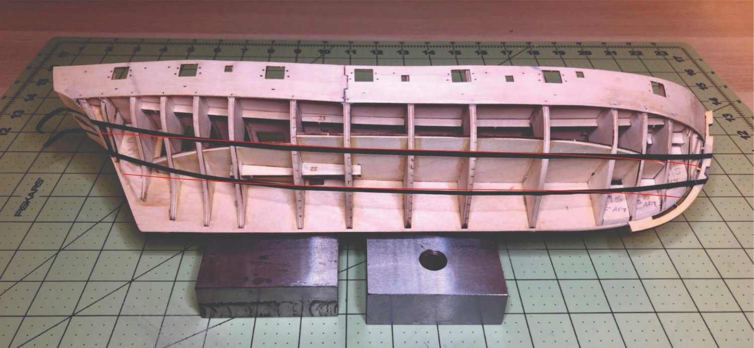
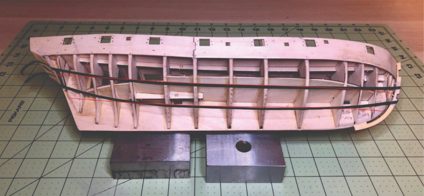
Those bands as lined off are incorrect. You have way too much upward sweep at the bow on those belts. Something more akin to this would make life a lot easier.
-
I just saw your build log and since you faired the bow inboard and out prior to planking, you will certainly have to be very careful. As you plank up there you will now be in danger of distorting the shape at the bow because the bulkhead frames are so thin. You will end up with the incorrect shape. This is why I write that you should wait until after planking is finished and the frames are thicker and stronger so they wont flex and distort. At the bow you can remove some of the material to cleabn it up as I did. You can do a general clean up inboard and start to even it out but I wouldnt reduce it to the final thickness yet. Just try not to deviate from the instructions moving forward. Most that do end up with some serious problems to fix later on. Chuck
- 1,784 replies
-
- 3
-
-
- winchelsea
- Syren Ship Model Company
- (and 1 more)
-
Its different widths at different times. Those quotes you posted are from different chapters. You are reading too far ahead and the widths change depending on what inboard/outboard planking is added. Just follow the instructions in a linear format. when you first start on the q deck you add the narrower strip. No planking yet. Then after planking its wider….the outboard planking being 3/64” thick. Hence the now wider strip added to the cap. Its different for each stage of construction which you are mixing up. Inboard fairing isnt done until after the outboard planking is finished. This is for a reason. The outboard planking makes the area stronger so you wont break the framing. It would be sanded too thin otherwise and be structurally weak. You should NOT be fairing inboard to the final thickness before planking. So just stick with that timeline and you will be fine. Otherwise you will certainly run into serious issues later.
- 1,784 replies
-
- 6
-
-
- winchelsea
- Syren Ship Model Company
- (and 1 more)
-
Yes they are. All very important. I am not sure what your question is.
- 1,784 replies
-
- 1
-
-
- winchelsea
- Syren Ship Model Company
- (and 1 more)
-
That looks pretty darned good. Well done. Glad to see an update.
- 99 replies
-
- 3
-
-
- winchelsea
- Syren Ship Model Company
- (and 1 more)
-
Nicely done...
-
Chapter 10 materials list Materials List for Winnie Ten.pdf
-
Probably.....I am hoping to start making them next week.
- 1,784 replies
-
- 5
-
-
- winchelsea
- Syren Ship Model Company
- (and 1 more)
-
I would check the original draft. This usually indicates which ways the doors opened and where the bulkheads were. In the case of Winnie this was changed a few times as indicated by different color new lines. It also varied depending on which ship it was in the class. But the drafts should show this very well if you have a deck layout sheet.
- 857 replies
-
- 2
-
-
- Sphinx
- Vanguard Models
- (and 1 more)
-
None really. Its all the same. I have a cheap $30 toaster oven. It works a treat. It has a rack and that is all you need. Bake at 275 to 325 degrees for about 5 or 6 minutes. its easy peasy.
-
Those carriages havent been made yet. Its on the list. The Binnacle parts are included in chapter 10. The binnacle is not a mini kit, although it may become one soon so folks can use it on other appropriate models. ….and yes, if you examine the plans you will see swivel guns and mounts. That is part of chapter 11.
- 1,784 replies
-
- 9
-
-

-
- winchelsea
- Syren Ship Model Company
- (and 1 more)
-
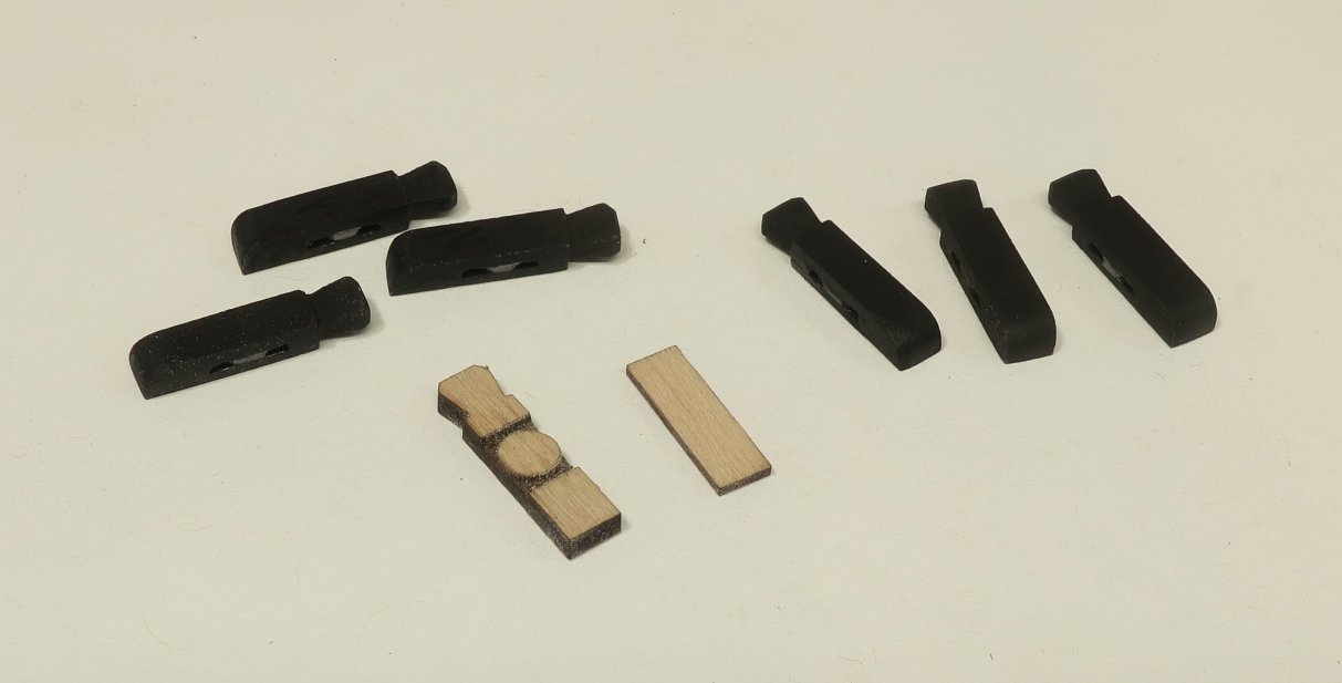
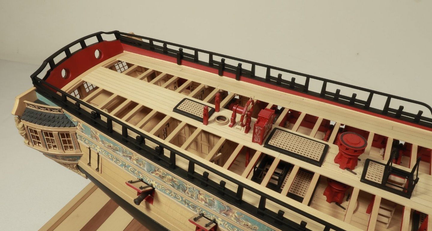
One of the last items to make for chapter ten are these fairleads that are positioned along the inboard side of the qdeck bulwarks. They are basically like timberheads with a sheave. They are used to belay the falls for the upper ropes of the main mast and mizzen. Now I originally placed I believe 5 of these on each side. But recently I have learned there were only three. I also now have better images of the contemporary model which also confirms this. So if you are examining the plans. You will ONLY be adding the aft-most three of these on both sides. This matches the Winnie contemporary model along with several others. They are easy to make and laser cut in two layers. Just glue the thinner 1/32" thick layer (this actually becomes the back side against the bulwarks) to the thicker layer with the sheave etched in it. Then sand the char and even out the sides. You will have to shape the top of the timberhead as the others with a sharp blade. Also round off the bottom front edge as shown below. Remember to round off the right side...….the front side. These are then glued to the inboard side of the bulwarks. They are exactly opposite the timberheads on the rail as you can see. This makes positioning them easy enough. They should be vertical. These are laser cut with the tops and bottoms on an angle. So there are port and starboard versions of these. Make sure you select the right ones for each side. Here you can see them in position on my model. Next up I will make the eyebolts and rings for the guns. These will be placed on the inboard side of the rail. Check the plans. Luckily we only have 8 to make so not as bas as making all of the eye bolts for the gun deck. In addition....because of the how we are planking the quarter deck, there will be no place to secure the eyebolts and split rings on deck. They would have fallen where we show the planking removed on the qdeck. Making the 8 six pounders and carriages will complete this chapter. They are sold separately as before. They are 1 9/16" long. I will place all 8 on the qdeck but be aware that in actuality only six would be placed there. The other two would have been on the fcastle. But as shown on many contemporary models they seem to place them all on the qdeck. My guess is they want to fill that dead space near the transom. Chuck
- 1,784 replies
-
- 29
-
-
- winchelsea
- Syren Ship Model Company
- (and 1 more)
-
I used a common glue stick....An elmers glue stick for crafts and paper. Works absolutely fine. I applied a light coat of fixative to the the friezes but you can do the same. Stand and spray from a good distance. Just a light coat if you want to add more. I used Krylon Matte fixative.
-
That looks really terrific. You would never know that this is your first ship model. This is NOT a beginner model and you are doing a fantastic job. You should be very happy with the results thus far. Chuck
- 155 replies
-
- 1
-
-
- Medway Longboat
- Syren Ship Model Company
- (and 1 more)
-
Simply wonderful Rusty....its a shame it will be mostly hidden. But at least we get a chance to see it here in the photos. Chuck
- 642 replies
-
- 3
-
-
- winchelsea
- Syren Ship Model Company
- (and 1 more)
-
Excellent planking...slow and steady. Your care with it shows beautifully. Chuck
-
Nicely done. That is some perfect rope.
-
Watch the first video part again... Note how at the end I use a small clamp to stop it from unwinding if you build up so much tension it starts to untwist. Usually only for really big ropes. Note how far I walked the head stock.....quite a bit for a short rope. That is a lot of twists. Dont be afraid to twist those strands a lot. and the second video just to complete the process. Remember that I am using linen/cotton thread in the videos. If you are using poly.....tie a knot on both ends and bake your rope in the oven as I detailed in this topic below.
-
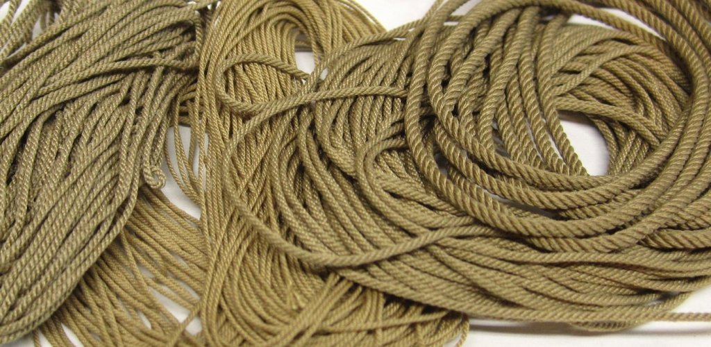
Nice try. Keep at it. But yes you need to probably increase twists on both ends quite a bit. Probably by a multiple of 5 or more. Dont be afraid to really twist it. Those examples are much to loose. For comparison ...look at this rope. The lay should almost be at 90 degrees to the rope before you cut it free. Then harden the rope and it will relax a bit more and up with the correct angle and tighter lay. If built properly the head stock will not (should not) rotate when you start laying up the rope. If it does, that means your gears are way too loose. If in the rare event that you build up so much tension in the head stock eye hooks that it starts unwinding. You should either tighten the gears more or place a clamp on one eye hooks to prevent it from spinning. But that should not happen unless you are making huge rope with a ton of tension being built up. I can tell from your photos however, that you are under-twisting by a whole lot.......a whole lot.
-
That is really coming together. I hope to see it again in person at the CT show in April.
- 642 replies
-
- 3
-
-
- winchelsea
- Syren Ship Model Company
- (and 1 more)