

tlevine
-
Posts
1,956 -
Joined
-
Last visited
Content Type
Profiles
Forums
Gallery
Events
Posts posted by tlevine
-
-
-
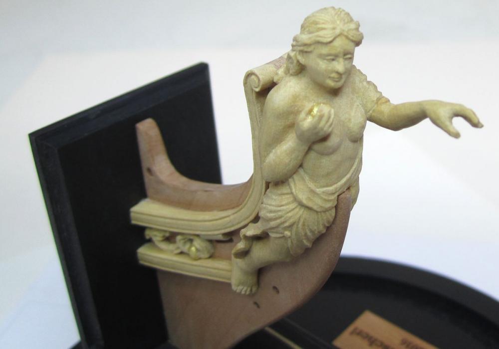
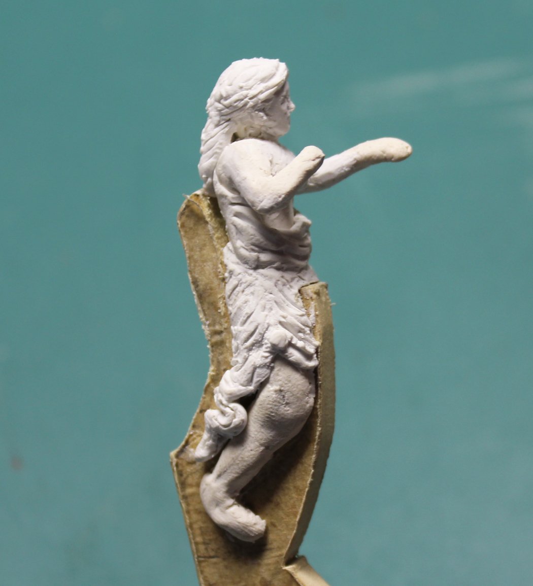
I have started work on the dreaded figurehead. I decided to make her out of clay rather than attempt carving. I felt sorry for the wood that I would butcher. Thank you to Chuck for his clay sculpting lesson and thank you to David Antscherl for carving a figurehead of Atalanta for Chuck. The photos he took and posted on MSW were a godsend. Here is the link to those photos.
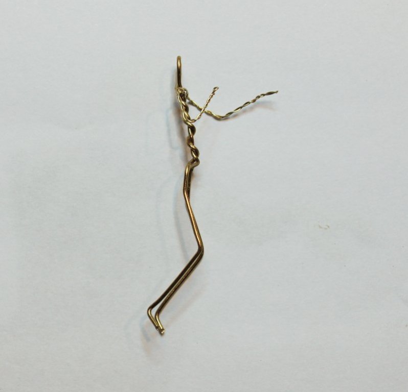
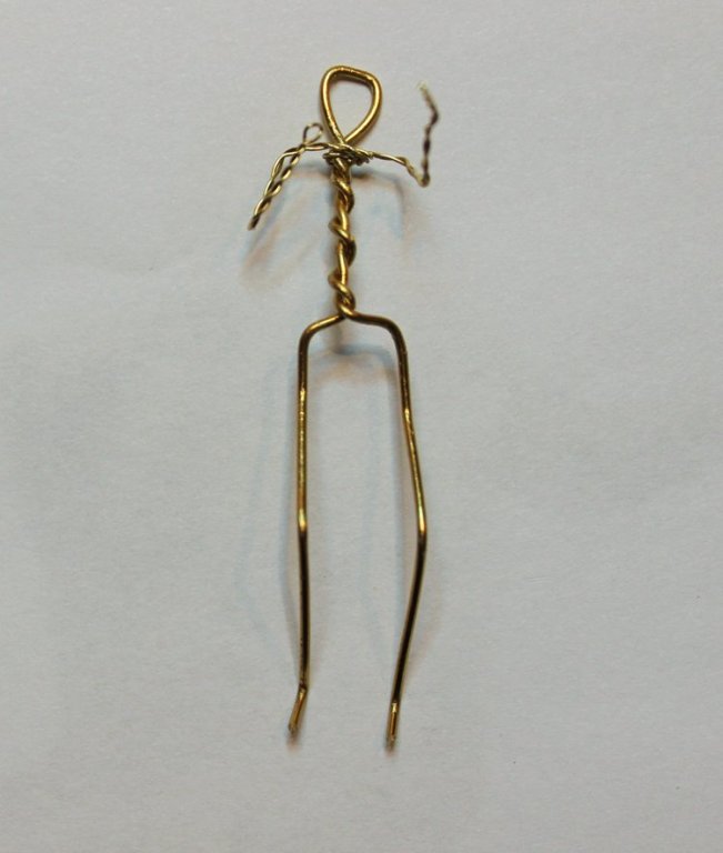
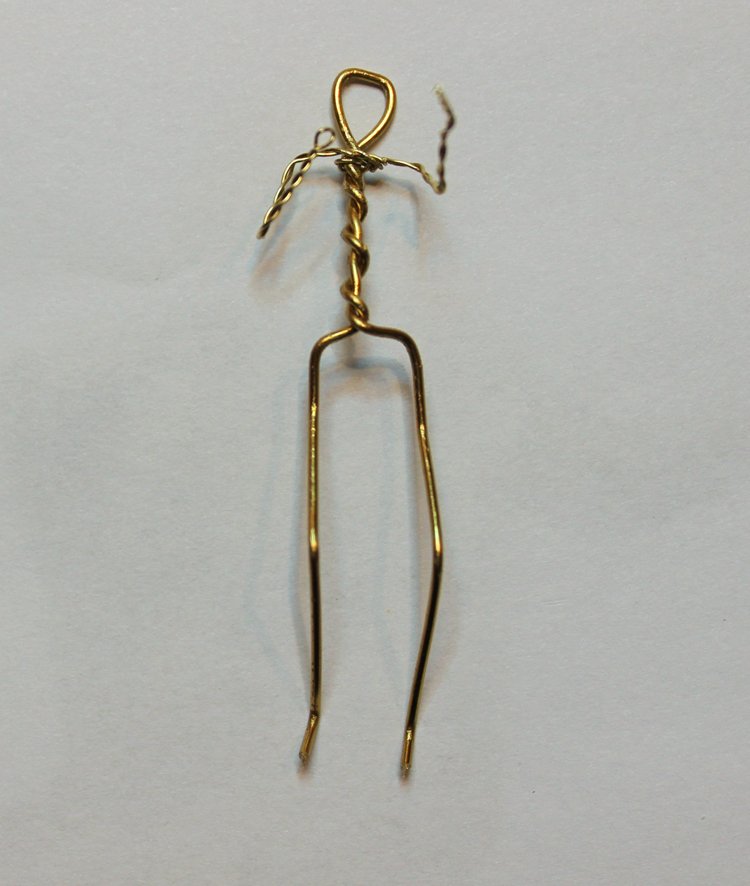
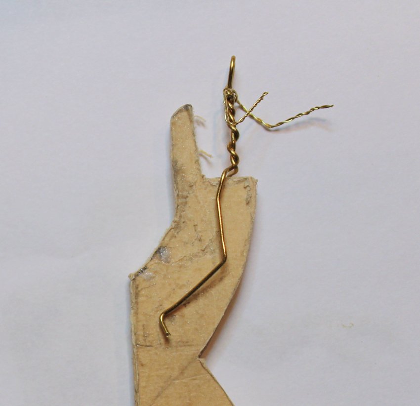
This is a copy of one of Chuck's photos of Atalanta. She is holding a golden apple in her right hand. The first thing I did was make a wire armature. This provided more strength to the arms and legs. I mounted the armature over a mock-up of the stem.

The first layer of clay was applied. I was not too careful with this as it was simply a base to build upon. I used white Sculpey clay with a few drops of softener added. After every significant addition I baked the clay per the instructions to harden that section. I think the biggest piece of advise that I can give is be careful with your proportions. Stand in front of a mirror. Your wrists hit the femoral head. Measure a female hand for the correct length (mine is 6"). How long is your torso in relation to your legs, etc. The breasts are not cones, as you can see in the picture above.
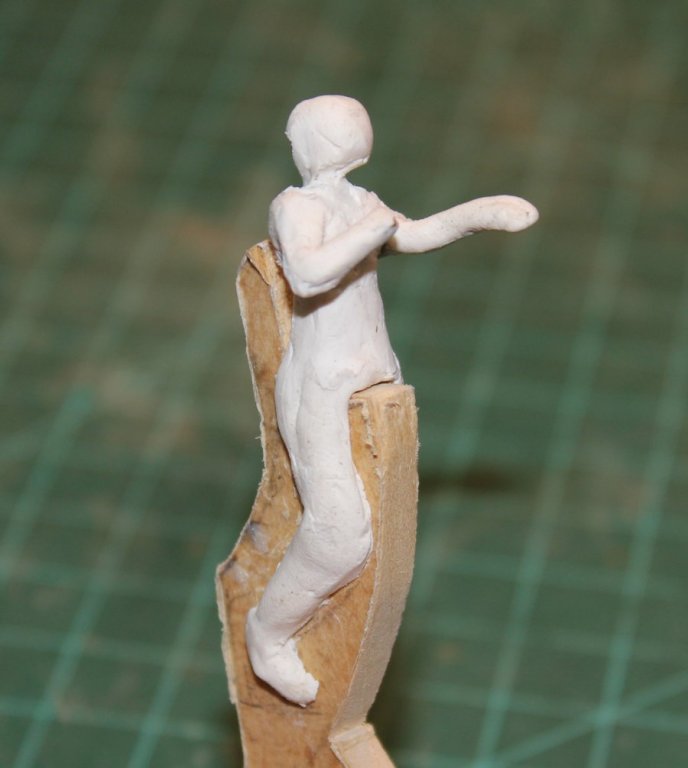
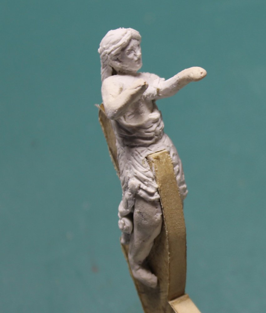
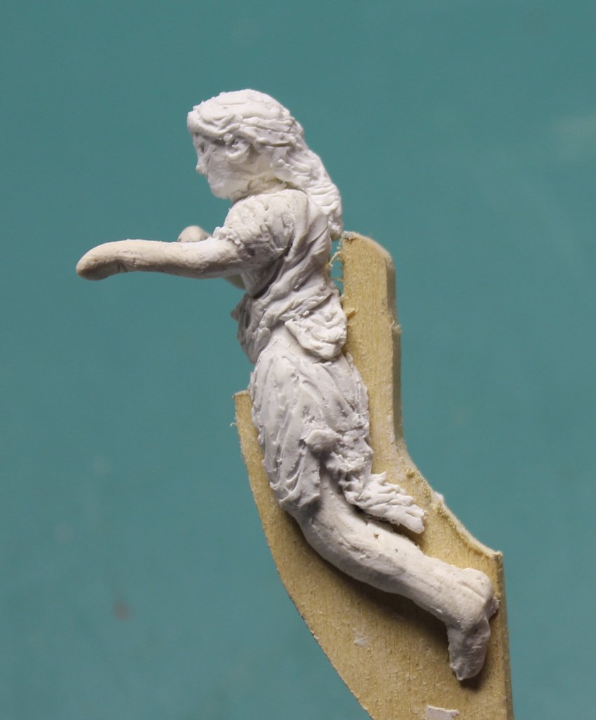
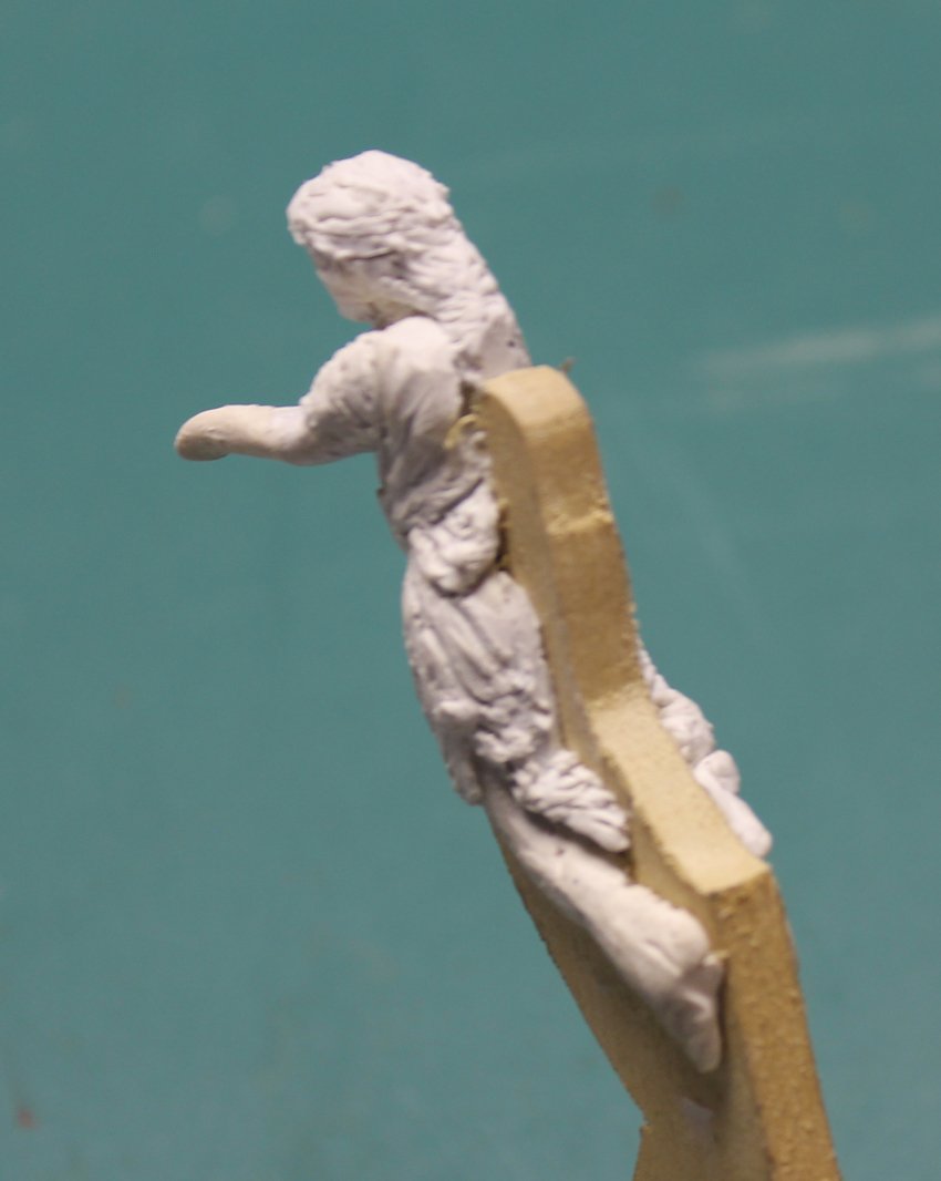
I decided to add the clothing and hair after I had the proportions correct, leaving the details of the hands, feet and face for last.

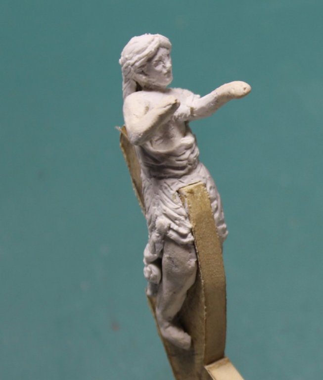


After the other details were completed I test-fit the figurehead to the actual stem. I discovered that I had forgotten to incorporate the taper of the stem on my mock-up and had to add extra clay to the medial thighs. Obviously there is still some finesse work remaining. I have a question for the members. Should I paint it white to minimize losing detail or in natural colors (white robe, dark brown hair, tanned skin). The apple will be gold, either way.


- Geoff Matson, JOUFF, tadheus and 32 others
-
 35
35
-
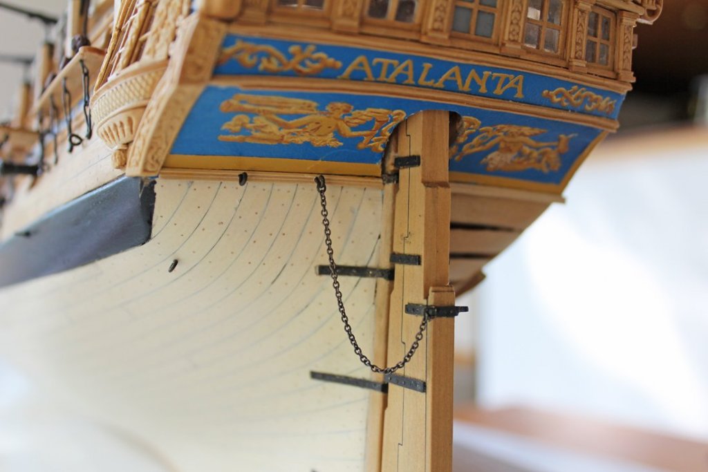
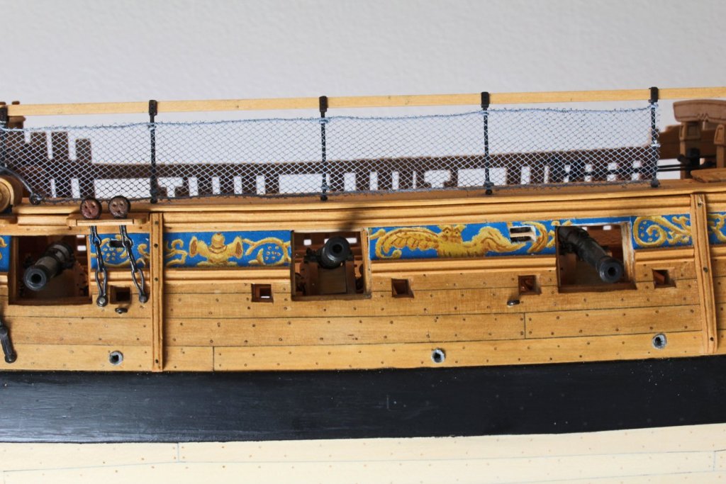
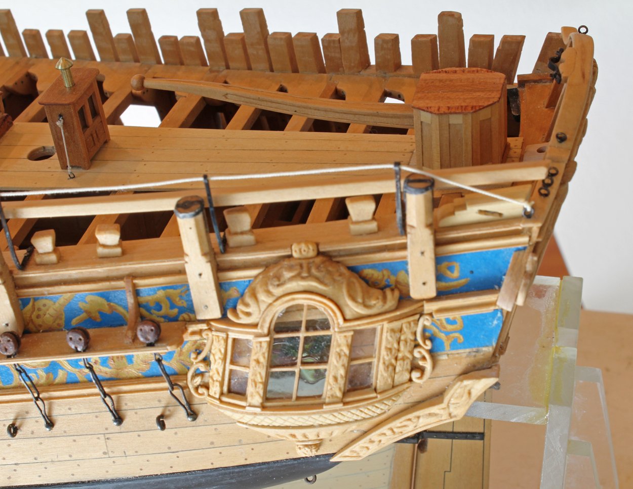
Greg had drawn it to my attention that when I rebuilt the rudder head cover I had forgotten to add the sill. Greg, this one's for you! You can also see the gunport tackle and tubes. The tubes are made of leather which I simulated with rolled paper dyed with brown Rit.

The rudder chain has been installed. It attaches onto the spectacle plate with a U-shaped tackle. The last things on my punch list are the figurehead, cleaning and paint touch-up. After my experience with the upper quarter carving the figurehead has me terrified.
-
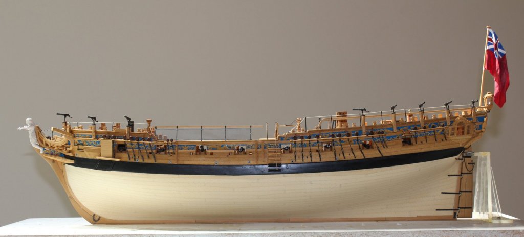
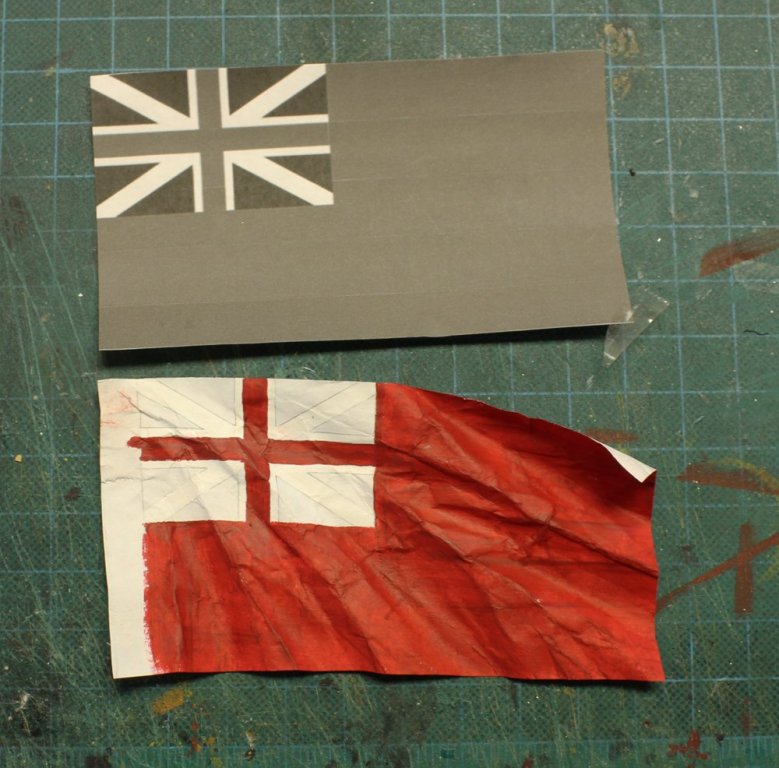
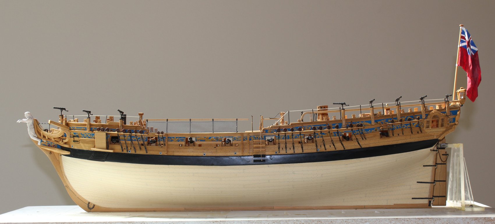
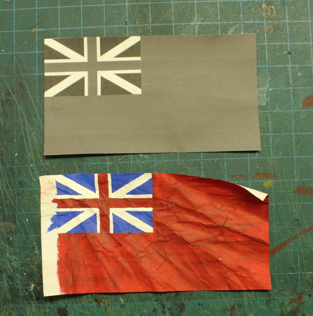
I debated back and forth whether I should put a flag on the ensign staff. Although few models of this style are shown with flags, I decided to make one. My reasons were that the model needed a pop of color and I had never made a flag before and wanted to see if I could do a good job.
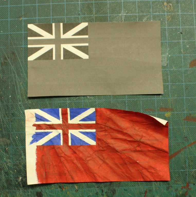
The technique that follows is exactly what was demonstrated by Gus Augustin at an NRG Conference a few years ago. I determined that the correct flag for 1775 was the red ensign. I drew the outline onto both sides of a piece of plain copy paper with pencil. Next, I cut the flag out, leaving extra paper inboards to make straps to secure the flag to the staff. The flag was shaped by crushing it in my hand, being careful to leave the inboard edge flat.
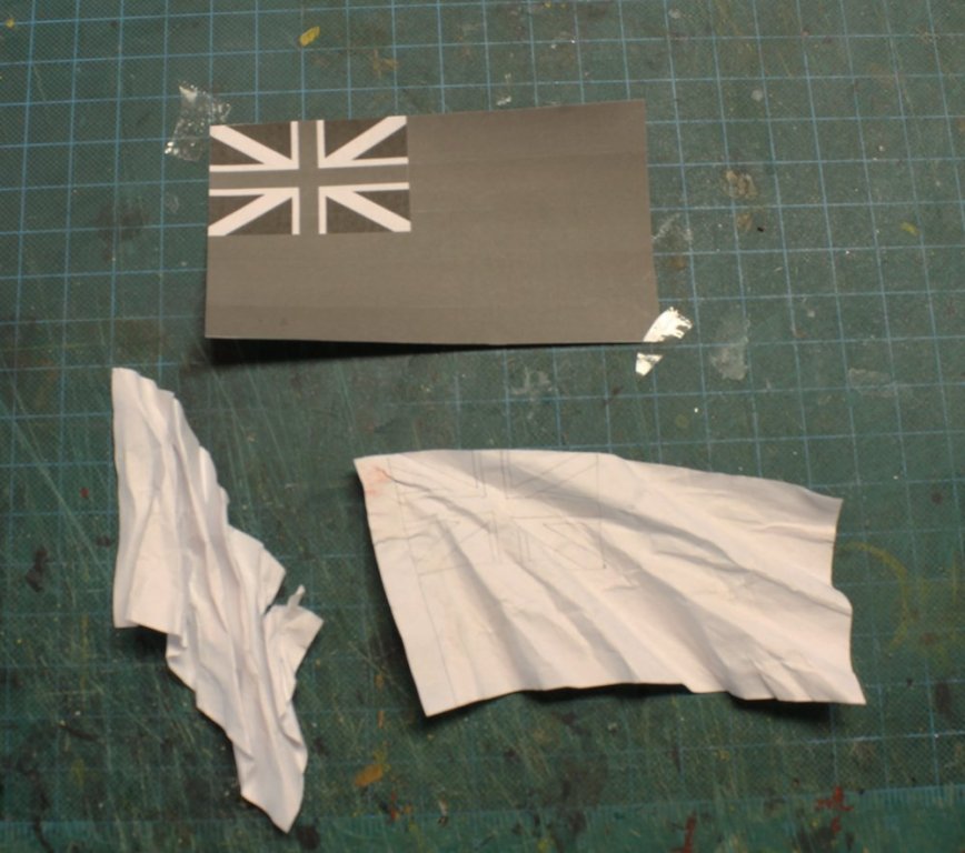
The flag was gently wet in a bowl of water and the crinkled shape was formed after laying the wet flag on a piece of glass. I did not touch it again for a few days but Gus states that one should wait at least 24 hours. The flag is then (sort-of) flattened and painted. Start with the light colors and gradually go darker. I used Poly-S and Model Master acrylic paints full strength.
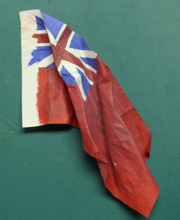

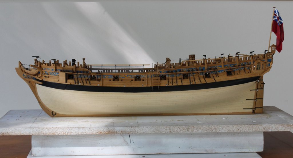
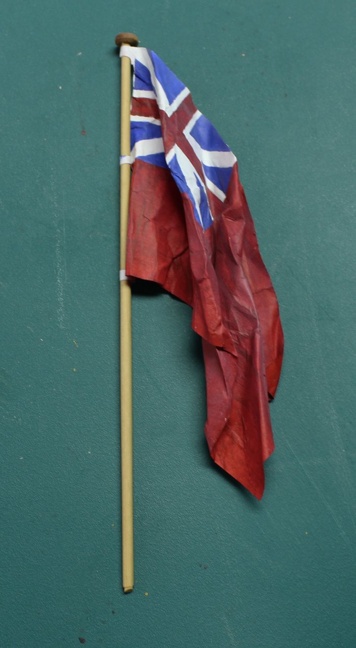
Once the flag was dry I air-brushed it very lightly with gray to soften the colors. Finally, I reformed the flag and secured it to the staff. Overall, I am pleased with the appearance.


-
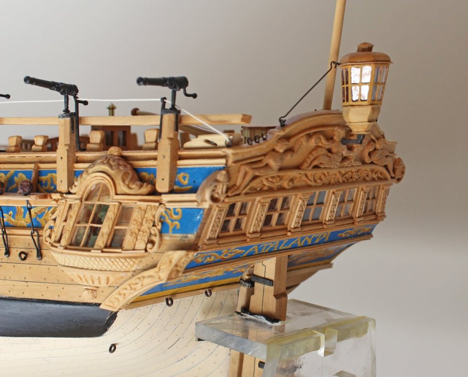
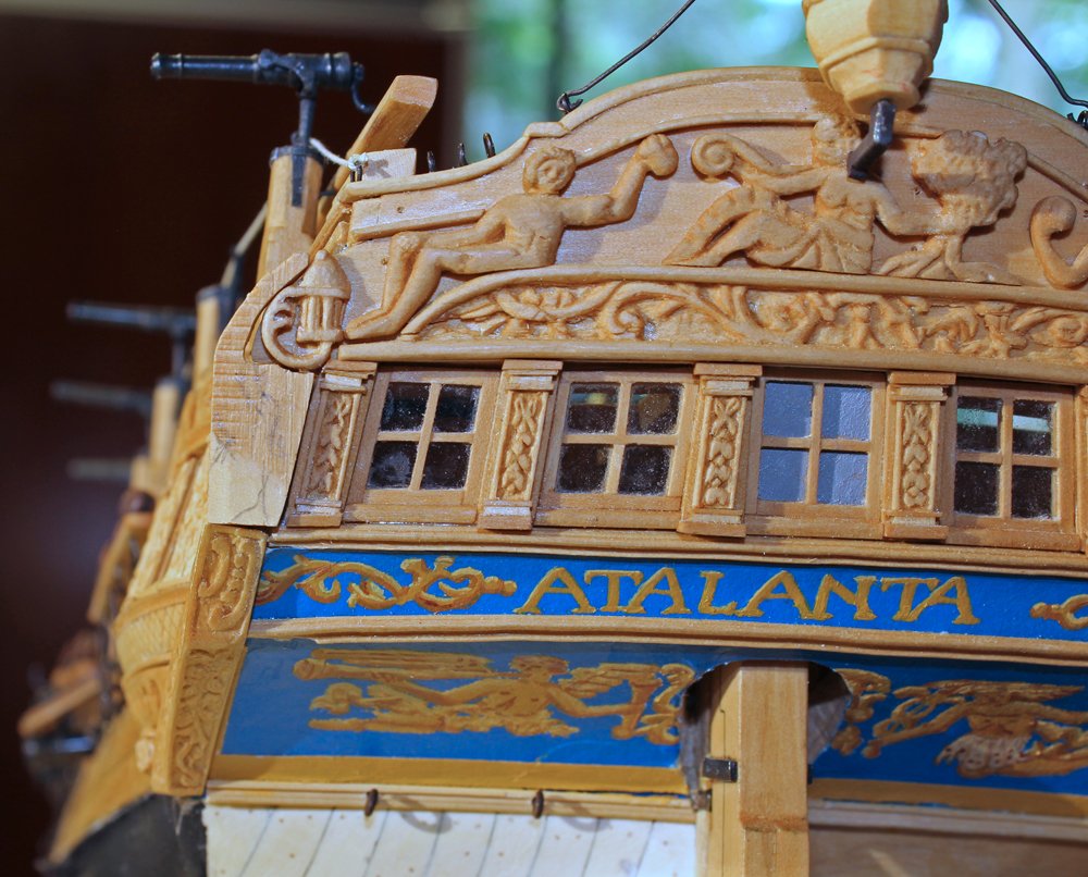
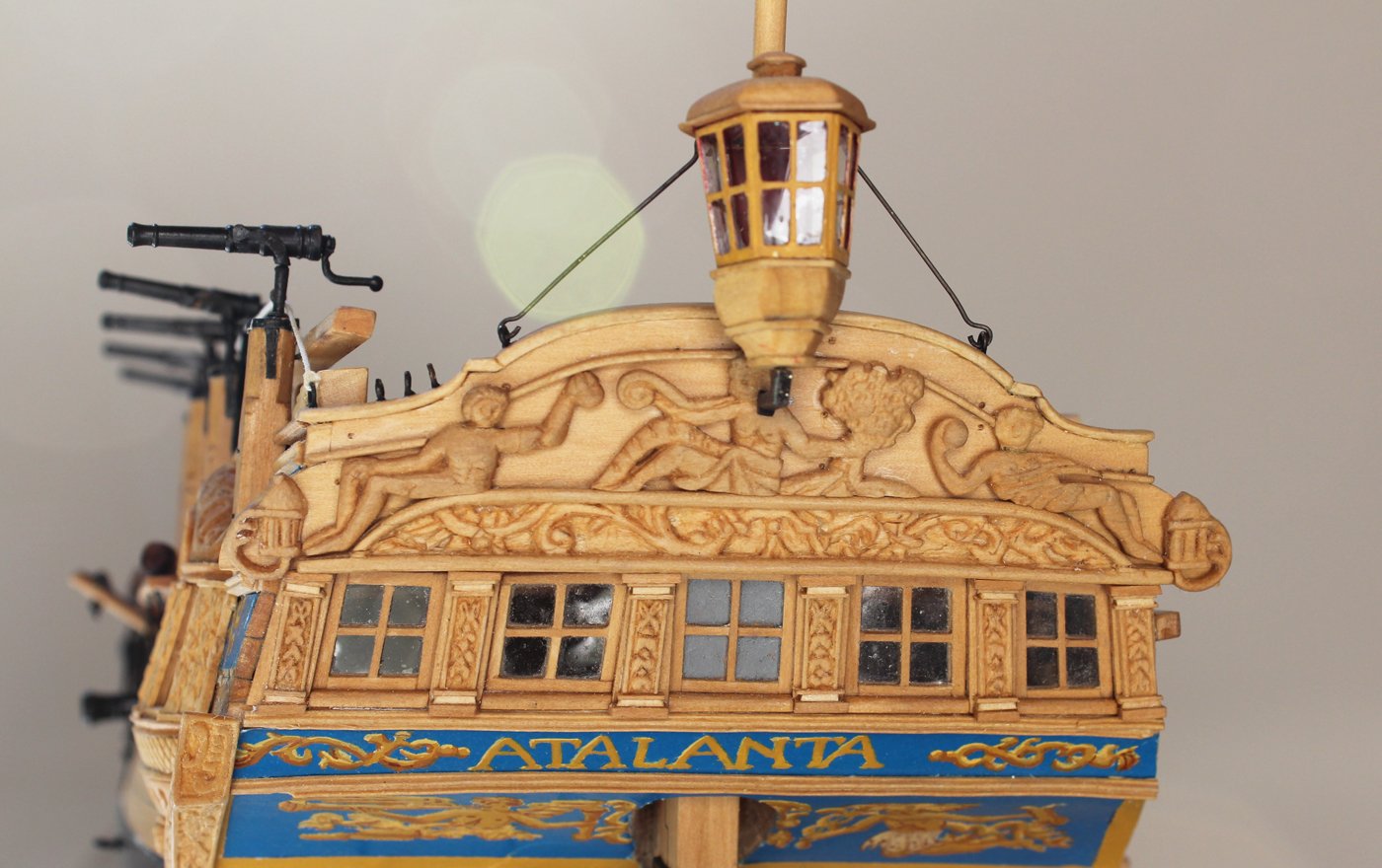
Karl, thanks for the tip. Some beautiful carving on those models. As my punch list has gotten smaller, I could not put off the upper quarter carving any longer. On both the plan and the contemporary model I could not tell for certain what the creature was. Because of the tail, I had to choose between a dragon and a lioness. I decided upon a lioness because that is what Atalanta was turned into after she had sex in a temple. The first thing I did was make an oversized mock-up of the carving out of Sculptey. Then, I made a second mock-up that fit into the space. Once I was satisfied with that I drew the outline on to a block of English boxwood. The color was a good match for the costello boxwood and I wanted the extra strength because of the tail.
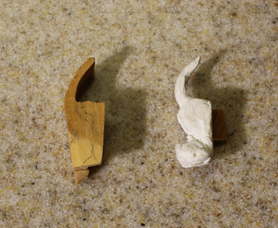

After a few failed attempts, the lioness slowly came out of the wood. The hardest part was the head, both the direction and appearance. Although in the pictures the face looks more like a bear than a lioness, it was the best I could do.

-
-
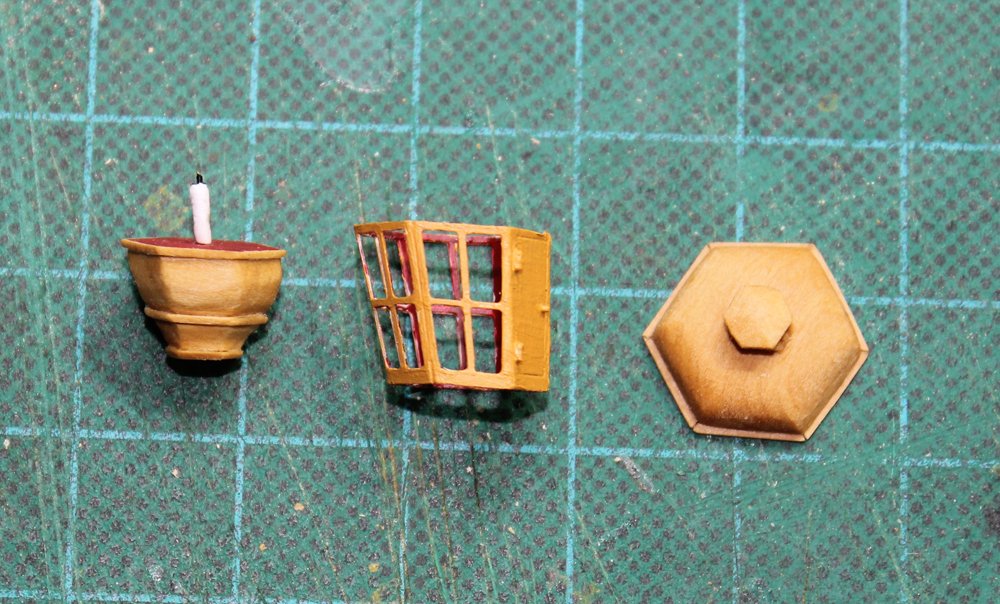
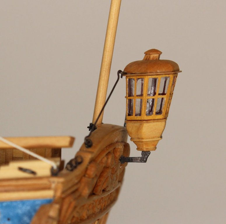
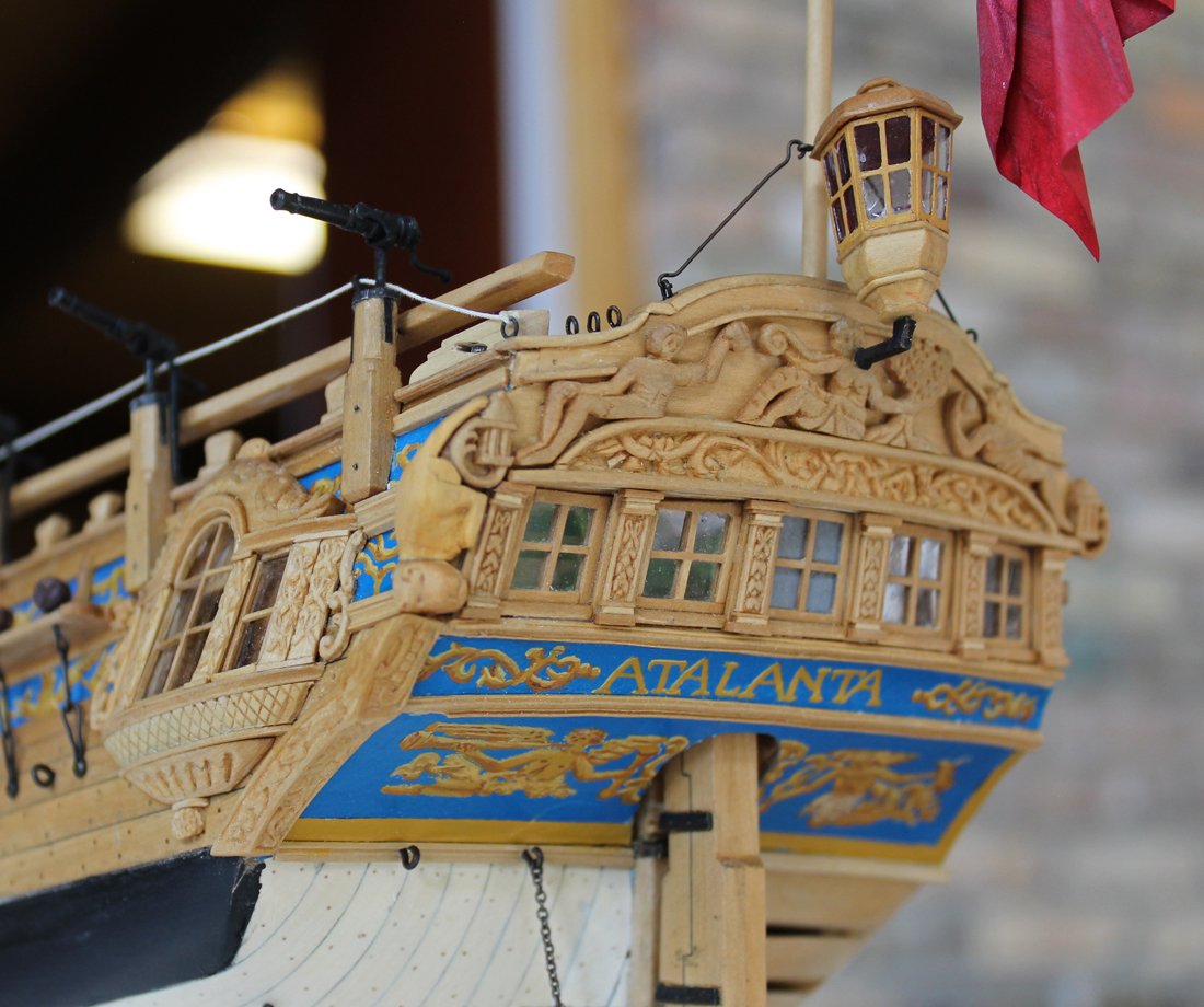
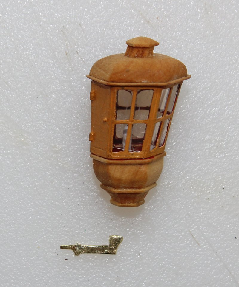
I have spent the last few weeks constructing the lantern. I used the brass photoetch from Admiralty Models for the carcass. Rather than post a step-by-step construction, take a look on their website. http://www.admiraltymodels.com/Tips.html The document is at the bottom of the page. The exterior was painted to match the wood and the interior was painted red. The candle is a roll of paper and the glazing is mica. The crank is brass which was cut and filed to shape. All metal was blackened.


- Captain Poison, druxey, Maury S and 22 others
-
25
-
The larger the number, the larger the diameter on DMC thread. When I started making my own line I purchased all of the sizes 20-100 and made test line do determine the diameter of the completed line. (All you need is a few feet.) The diameter will be different for right-hand vs left-hand line so if you plan on having the correct lay for the different lines you will need to lay up both left and right-hand test line. Remember, the line diameter will vary a little based on your individual technique.
-
One of the other reasons beginning modelers become discouraged is the length of time required to finish even a simple model. Most of us have built a number of plastic kits, either as a kid or an adult. Unfortunately, that leads to an expectation of accomplishment in a short period of time. To us, a quick model means completion in less than a year!
- JJolley, mtaylor, Rik Thistle and 4 others
-
7
-
-
-
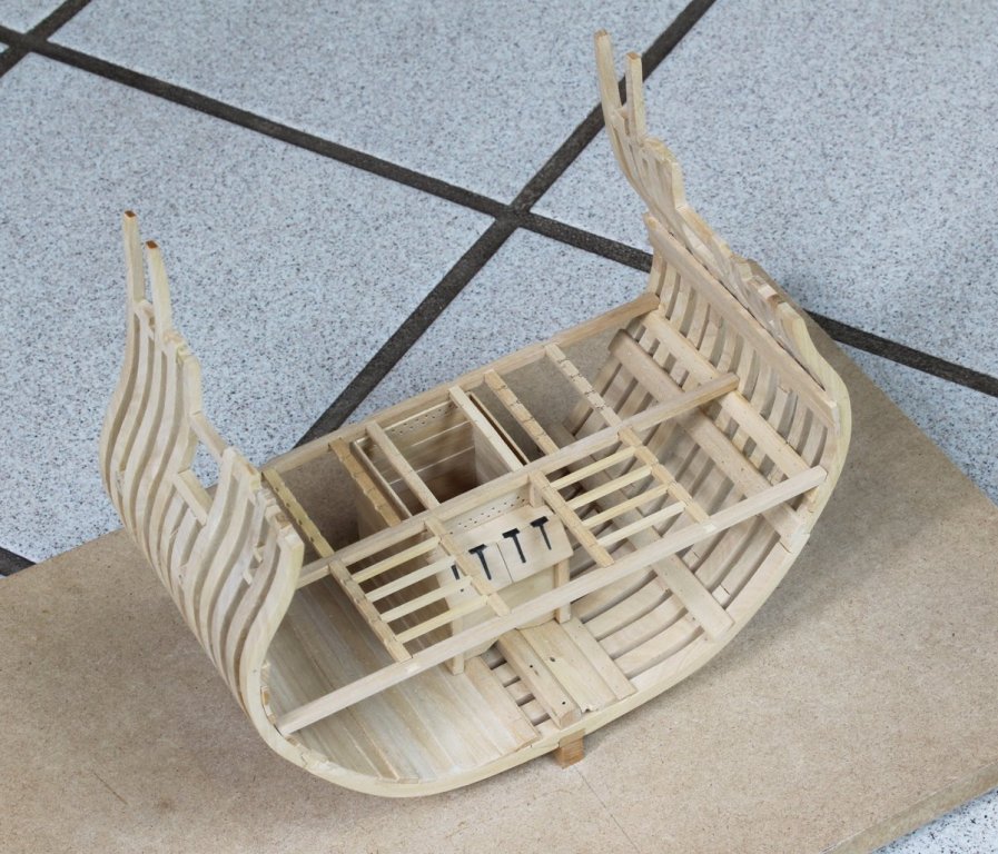
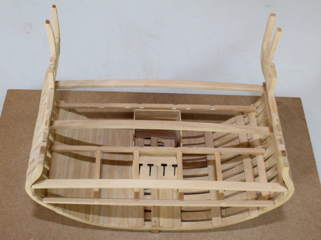
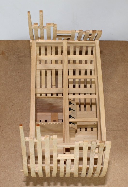
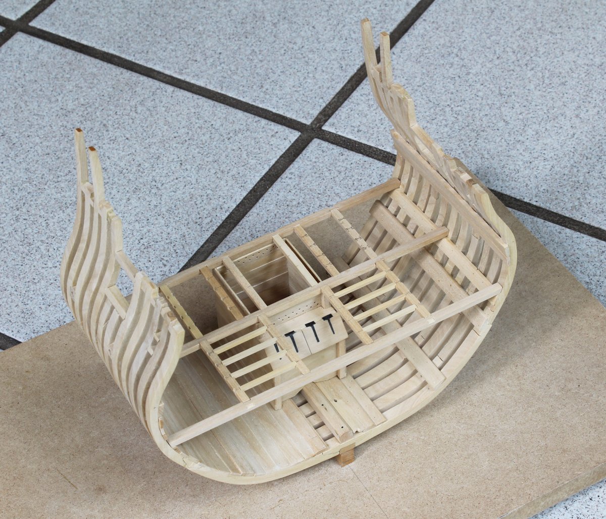
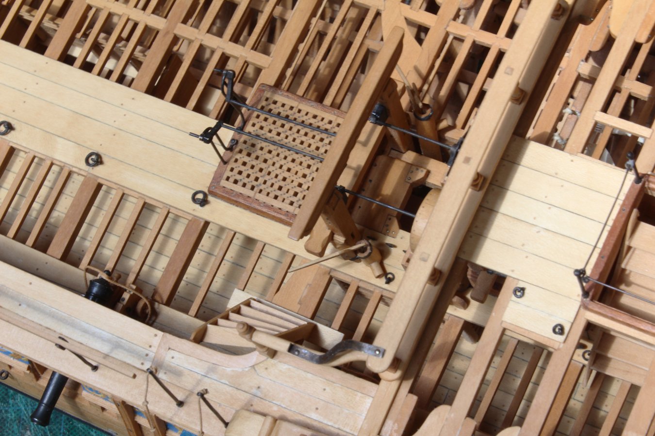
Just a quick update. The carlings have been cut to accept the ledges. I have started making the inner belt of ledges. The outer belt will not be make until the knees have been installed.
- MEDDO, VTHokiEE, Tigersteve and 13 others
-
16
-
Martin, I have a few ideas for the next build. Let's finally get through this one first!
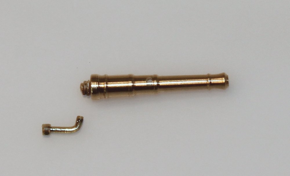
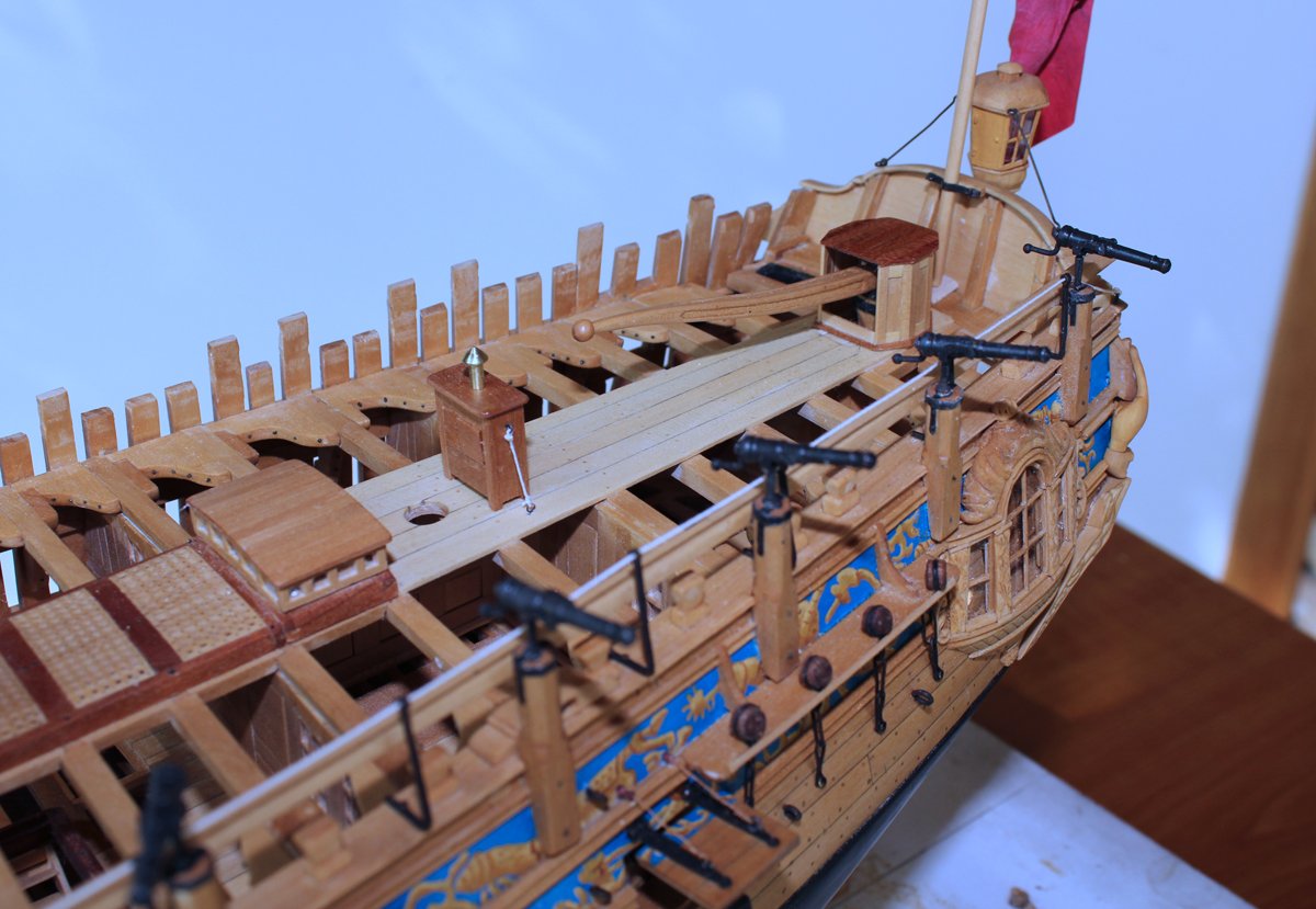
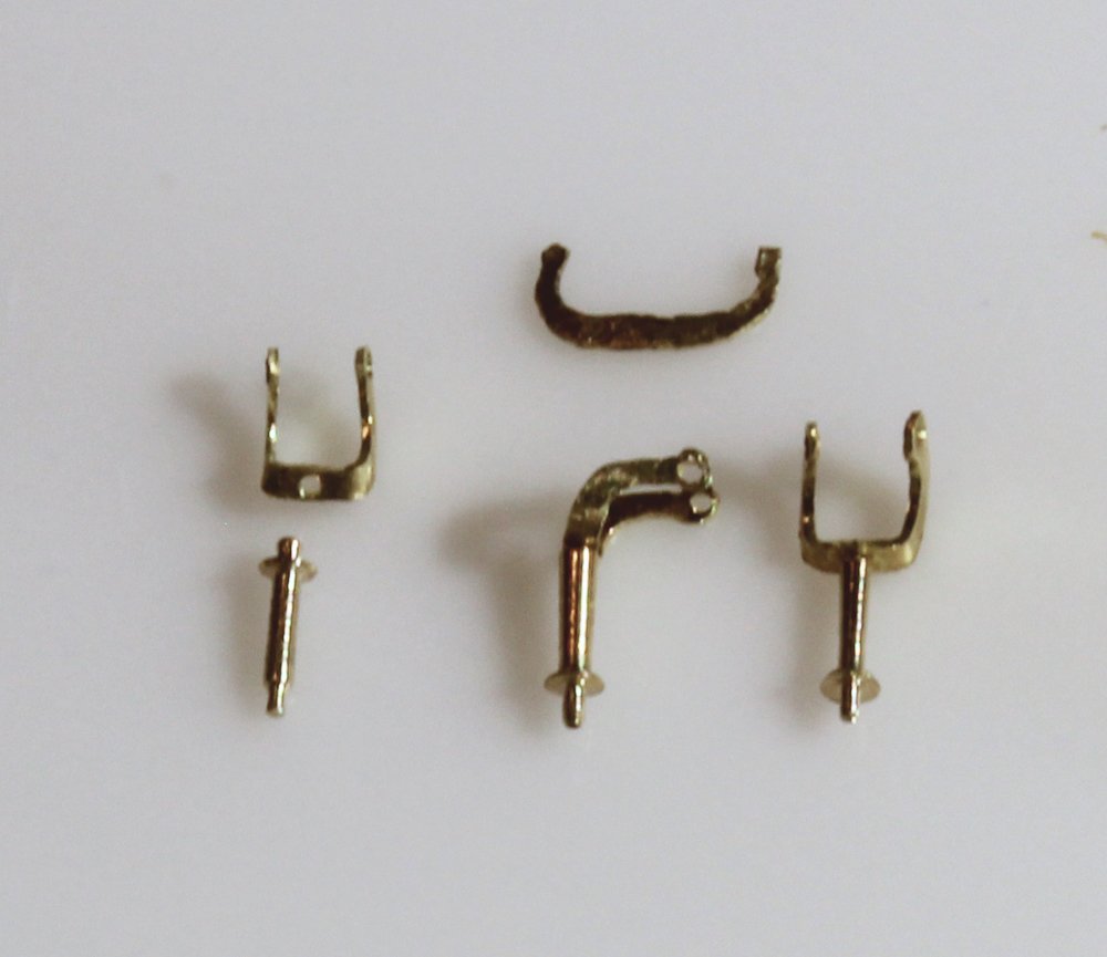
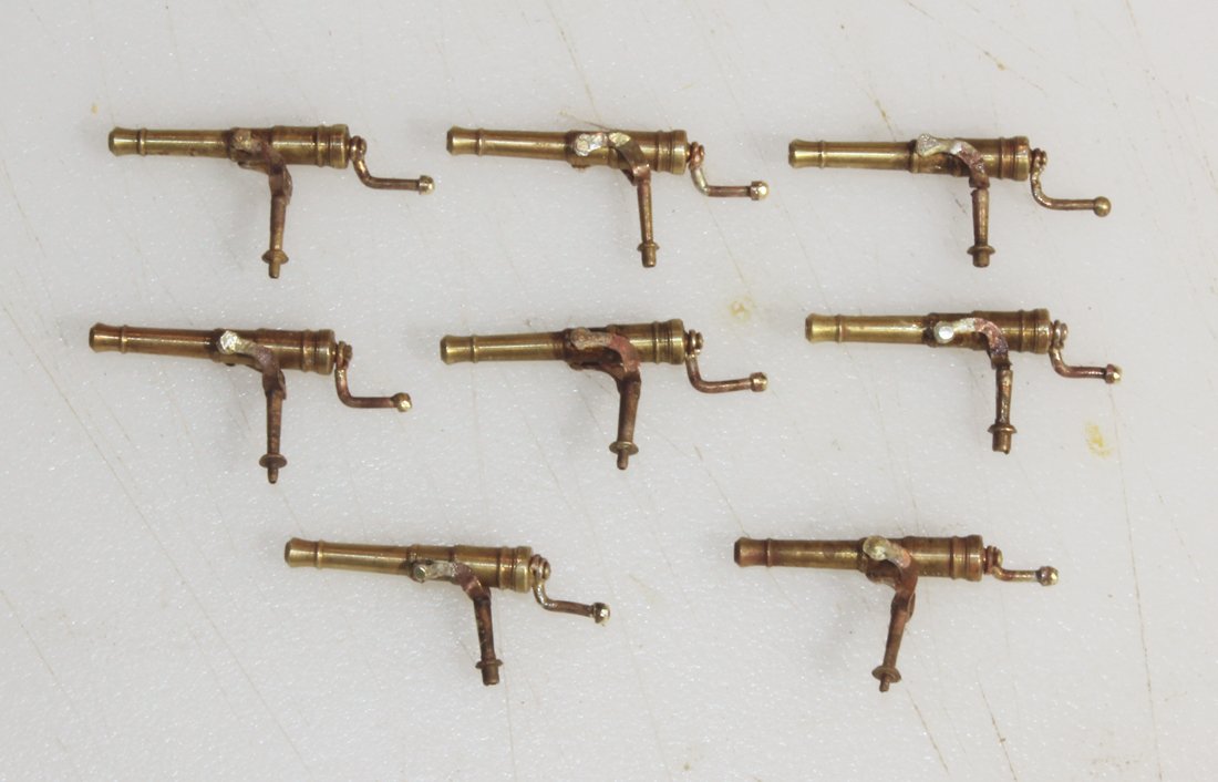
Since I will not be moving the model very much anymore, I decided it was time to make the swivel guns. There are a total of 16, eight per side. Five are on the quarterdeck and three are on the forecastle. I used barrels from Syren to make my life a little easier. There is an aiming handle mounted onto the cascabel. It is L-shaped, extending below the swivel gun. In order to solder this to the gun I wrapped a loop of brass wire into the neck and filed a flat surface into it on the bottom. This gave me good surface area for soldering. The ball at the end of the handle is brass tubing slipped over the wire. That will be filed down after soldering.
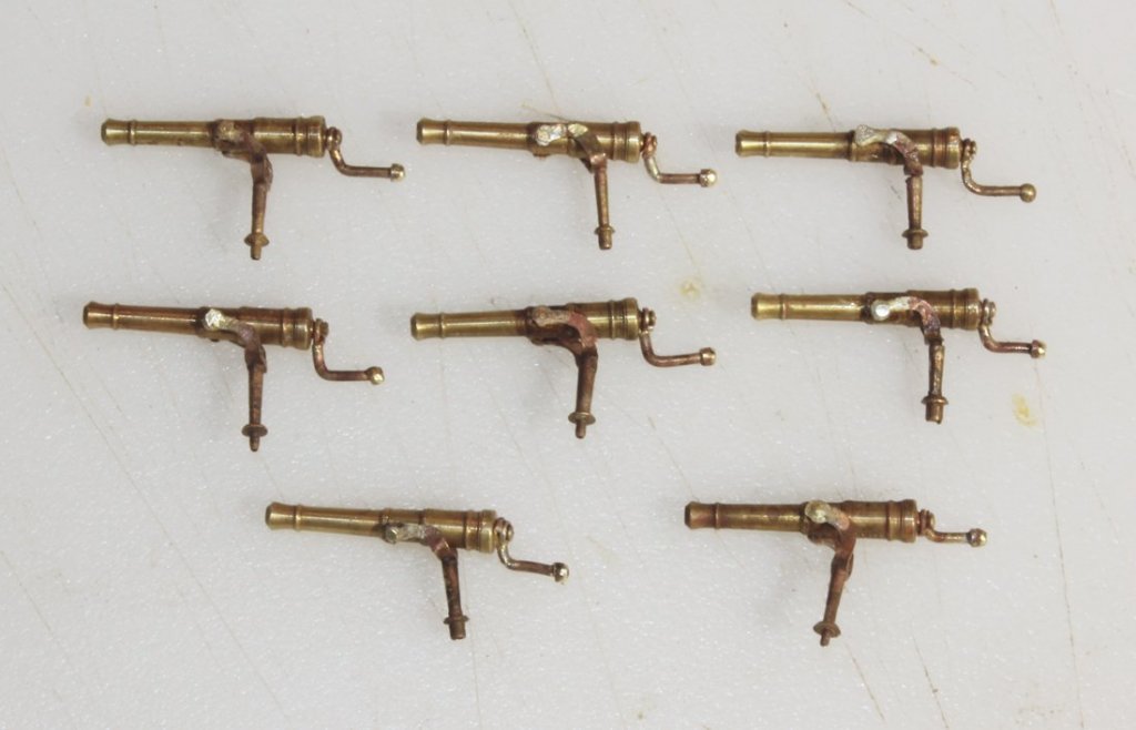
There are two types of swivel gun mounts: a simple yoke and the one used on the contemporary model of Atalanta. The yoke bends forward. According to David in TFFM, this gave additional clearance to decrease risk of damage to the shrouds. The first step was to make a paper template of the yoke. I then cut out a brass template (the smiley face in the top of the picture. This was made undersized to allow me to trace around it with a file to get the correct size and shape. Shaping was done with carborundum wheels, a cut-off wheel and files. Holes were then drilled for the trunion and mount. The mount was shaped on the lathe. The mount and yoke were then soldered together.

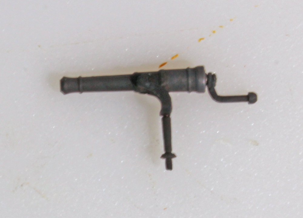
The pin was placed through the hole for the trunion and soldered onto the yoke. Next came blackening and finally mounting.


-
-
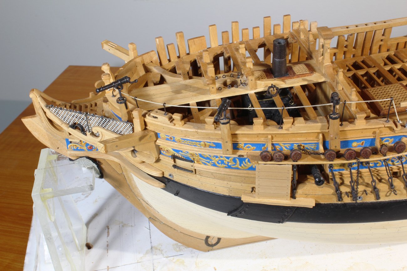
There are a lot of small projects to complete at this point. The first project was to start the cleaning process. After five years, the hull inevitably gets a little grimy, especially since it travels with me weekly on the back seat of my car. I started with compressed air to remove most of the sawdust. This was followed by moistened Q-tips and bits of paper towel held in a needle driver. This process took about three hours and will be repeated a few more times in the upcoming months.
One of my punch list items was to insert the nails into the ribbands. I had pre-drilled the holes at the time the ribbands were installed but deferred adding the nails so the blackening would not wear off.
I have put the ring on the anchor and applied the puddening. There is a first layer of rope with four seizings on top of that.
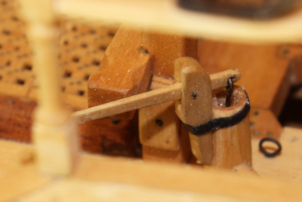
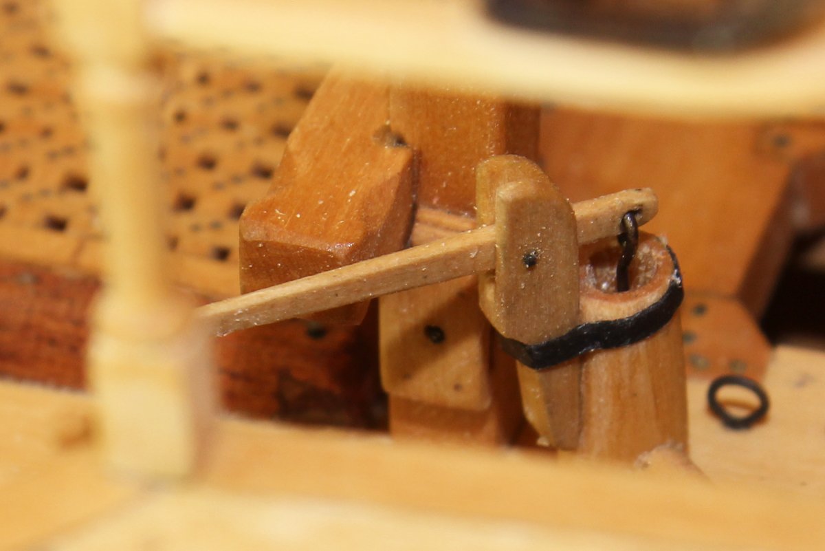
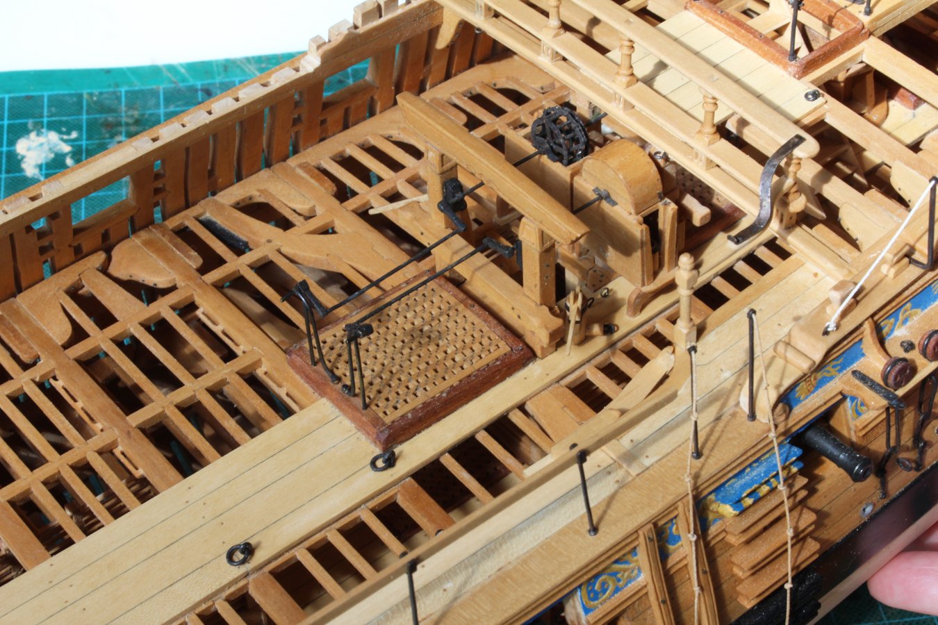
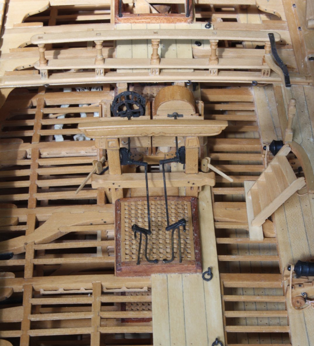
The elm tree pumps were installed earlier but I did not make the handles as I knew they would be damaged. Needless to lay, this picture was taken before cleaning. A bracket was shaped to the side of the pump tube and a slot was cut for the handle. The strap is from black paper.
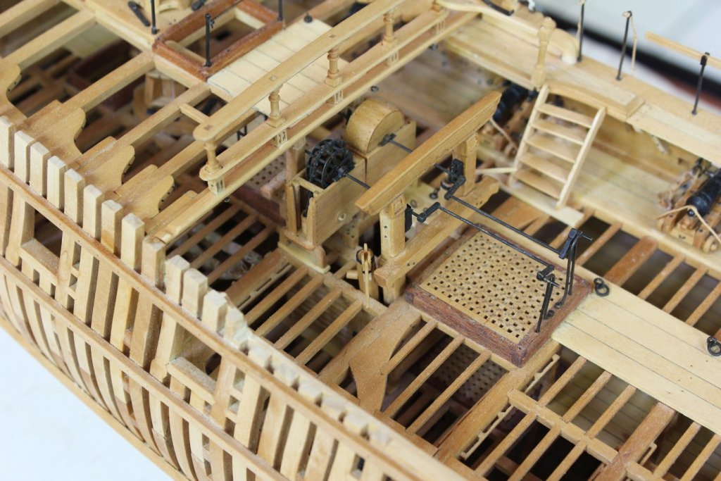


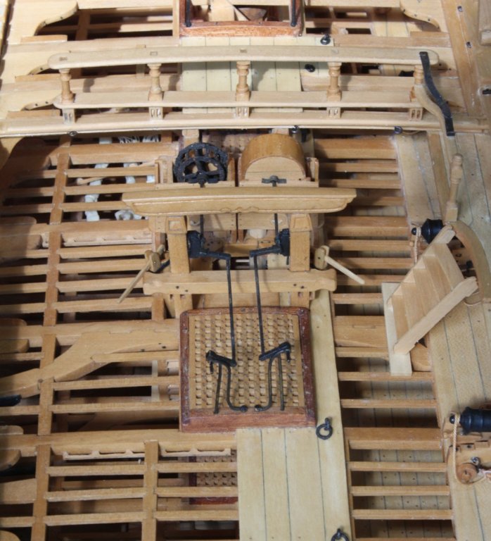
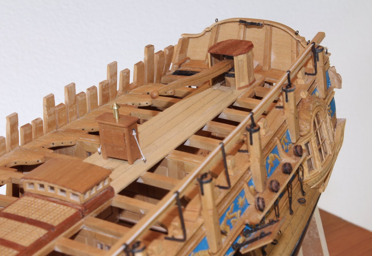
I shipped the rudder at this point and drilled out the aft plexiglass support to accommodate it. I discovered that the top of the rudderhead was taller than the rudderhead cover and so this had to be remade. I prefer the looks of this one as well. I also installed the binnacle cabinet and secured it to the deck with two ropes.


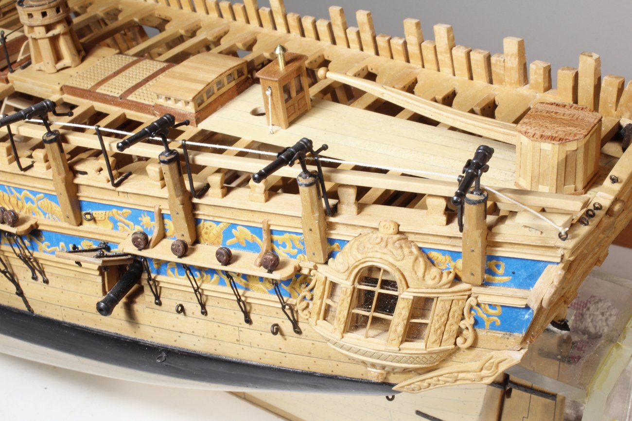
There is netting in the waist which is secured to the stanchions for the hand rail. This was made with tulle. The ropes are threaded through the netting and the entire assembly is spray painted. It was then trimmed and tied to the stanchions. As you can see, the cannon barrels are not even. Several of them have been jarred loose and need to be reglued.

- paulsutcliffe, russ, hollowneck and 25 others
-
28
-
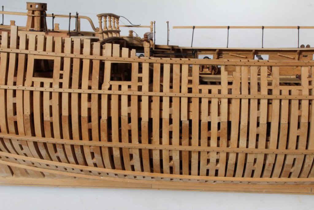
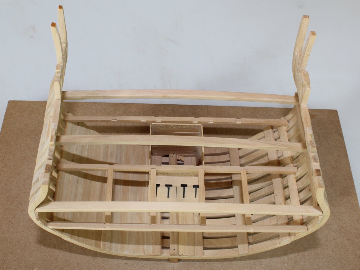
I told you this was going to be slow going! The upper deck beams have been fabricated. They will not be permanently installed until the lower deck has been completed. The lower deck beams have been notched to accept the carlings. The notched were made with a razor saw and 3 mm chisels. Four of the carlings have been temporarily placed between the beams. Hope to have another update soon.
- Ryland Craze, Canute, MEDDO and 14 others
-
17
-
Everything is looking good so far. Every so often take a strip of card (think magazine inserts or that paper that junk mail is printed on) and lay is across the bulkheads. It is flexible but has some strength, unlike regular paper. That will show will where more material has to be removed. When it lays flat from the midpoint to the stem and to the stern, you are done fairing.
-
-
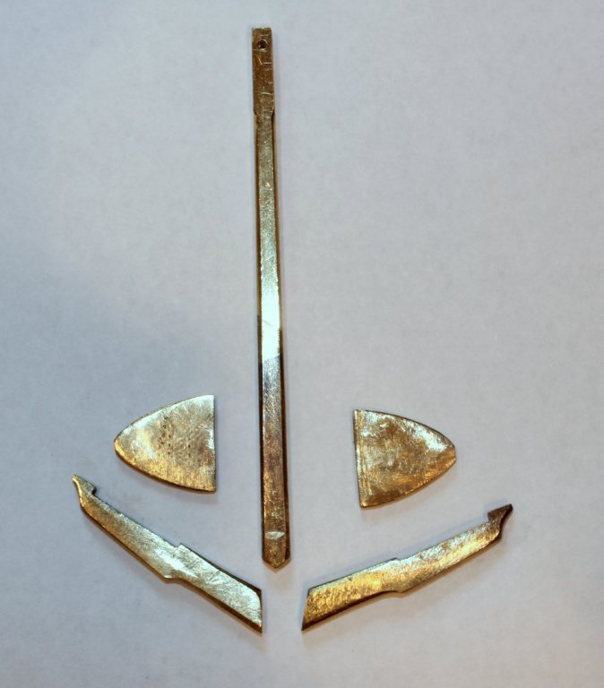
I chucked 1/4" round brass rod onto the rotory table of my Sherline mill. Then I slowly milled down the rod to the correct dimensions. The rotary table assured that the corners were at exactly 90 degrees. One of the problems I had was that towards the end, especially when the metal got thinner, the flattened rod would deflect away from the mill cutter. I used my finger to hole the end up to help prevent that. The minor defection was then filed flat after milling. The shape of the arms was made with an abrasive bit on the Dremel.
-
-
-
-
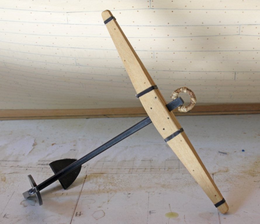
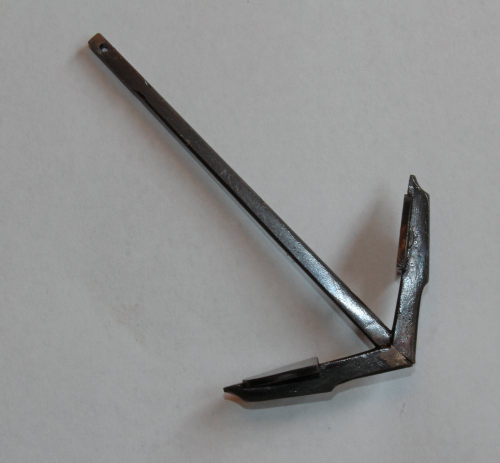
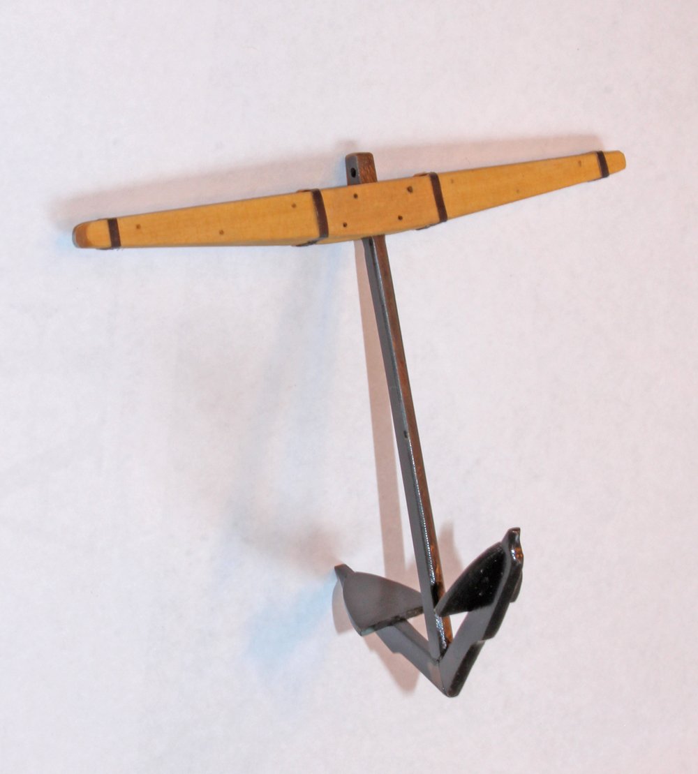
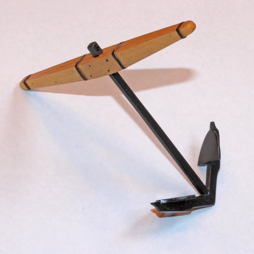
Thanks everyone for the nice comments and the likes. Next on the build list is the anchor. I am only making the port side anchor since the starboard side is only in frame. Previously I have made my anchors out of wood, painted to look like metal, but I wanted to make this one from brass. My options were to make the shank and arms from one sheet of brass (as Ed Tosti did for Naiad) or made separate arms and shank and then solder them together. I decided to to the latter as cutting out the anchor from sheet brass seemed overwhelming. My first challenge was finding the correct thickness of brass. I was unable to find any brass sheet or square rod of the approximate dimensions required. I found it necessary to purchase round rod and mill it flat to the correct thicknesses. Although not difficult, I found this to be very time consuming (probably because of my inexperience with milling brass stock). I was able to obtain brass sheet of the correct thickness for the palms. When looking at the pictures, keep in mind that this anchor, without the ring, is 3.25" long.
After I was satisfied with the final shape, the next step is to solder everything together. These pieces of metal are huge compared with the rest of the metal work on the model. Since I planned on blackening the metal, that meant silver soldering rather than soft soldering. I know some modelers get good results with Tix solder, but I have never had any luck with it when the pieces are to be blackened and not painted. My fist step was to solder the two arms together. This is when I discovered just how much heat was necessary to get the solder to flow on these large chunks of metal. Then I attempted to solder the shank onto the arm assembly. I put the solder on the arm joint and applied the heat to the shank but could not prevent the arm joint from falling apart just as the solder began to flow into the shank/arm joint. I do not own multiple melting points of silver solder so I pinned all the pieces together on a ceramic block and soldered all the joints simultaneously. Although not perfect, I think it looks reasonably good. If I were to do it again I would not file the edge on the top of the arm until after the soldering. The joint would look tighter and I would have been able to have a smoother transition on the outer edge from the arm to the shaft.
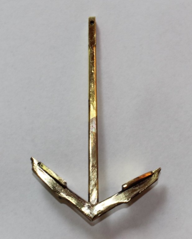
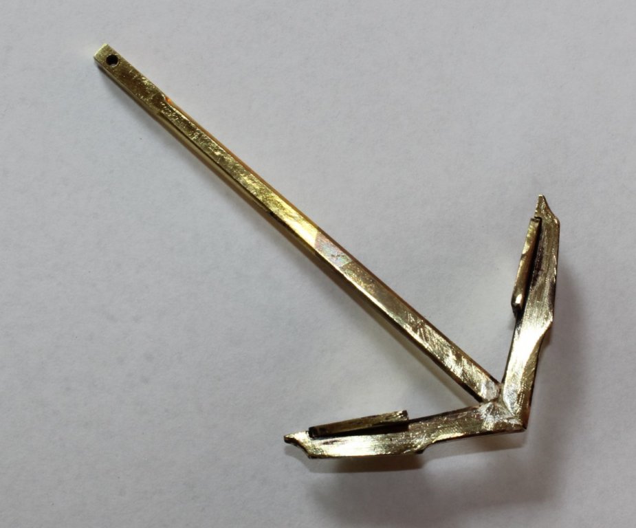
The anchor was pickled, blackened in 1:3 Birchwood Casey. Unfortunately you can see the difference between the brass and the silver after blackening. After I saw this I filed everything down where the silver flowed and although it is better, a discriminating eye can still pick out the difference. Fortunately, it looks a lot worse in the photos than it does in real life. After blackening, I applied a coat of matte clear finish.
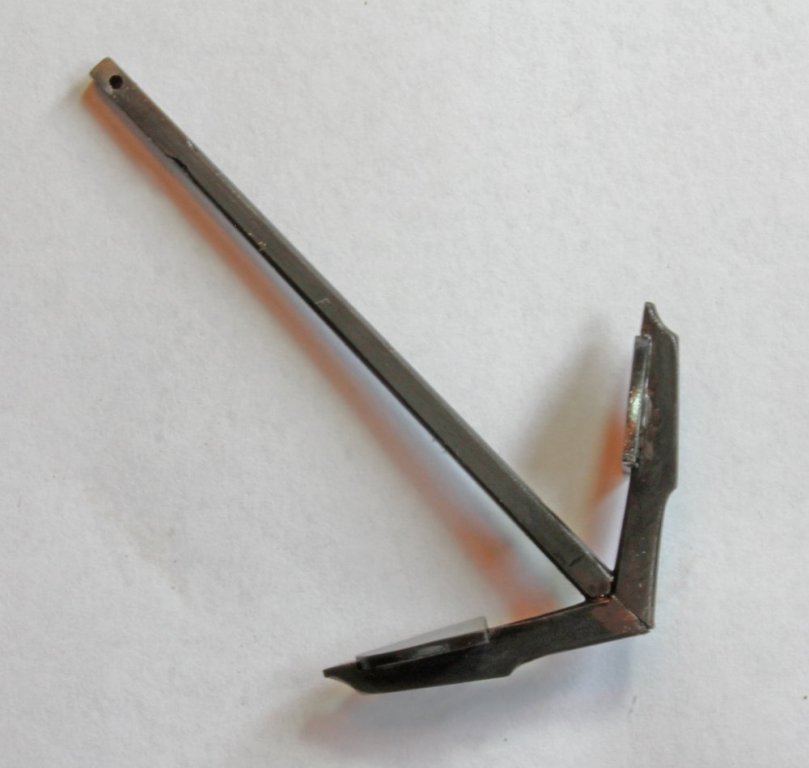
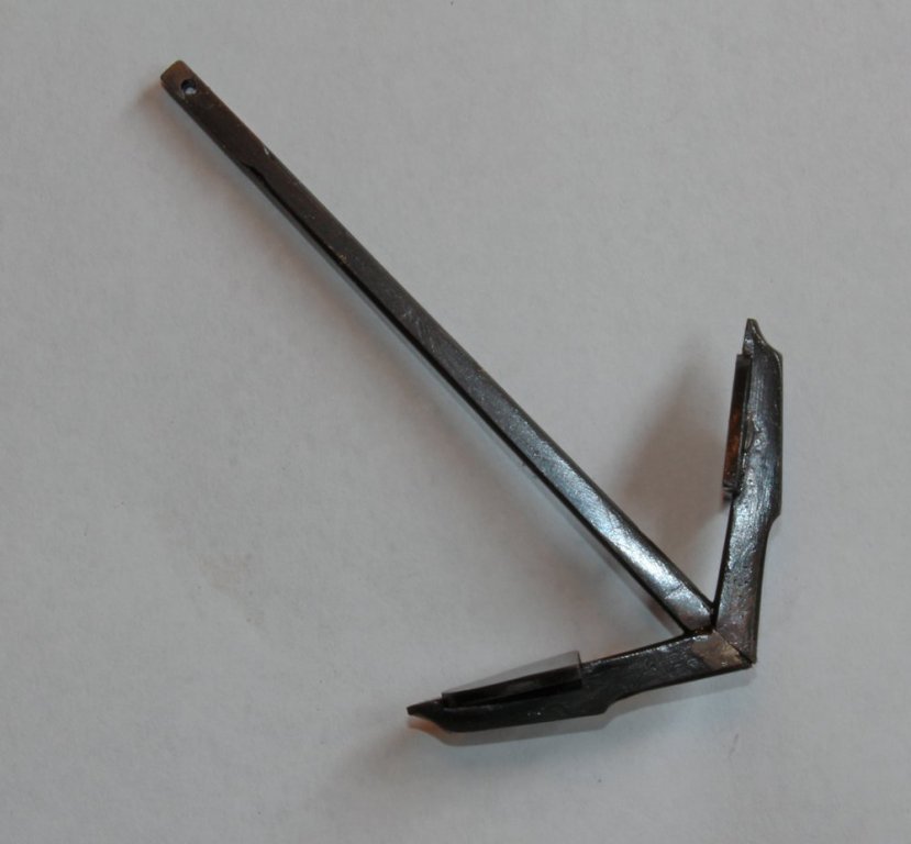
The stocks are relatively straight forward. There is an air gap between the two halves to prevent rot. In following David's drawings I noticed that the two halves are not mirror images. Only one half has the internal taper, the other half is straight internally. The two halves are bolted and treenailed together. The hoops are simulated by paper dyed with archival ink. I still need to install the ring.


-
Tom, the ship is being made per the as built plans. Maury, your eyes are too d*** good. I didn't notice it until you mentioned it. Well, it is too late now. Removing it would cause a whole lot of damage.
I have finished the anchor except for the ring. Hope to have some pictures to post in a few days.
- mtaylor and paulsutcliffe
-
2


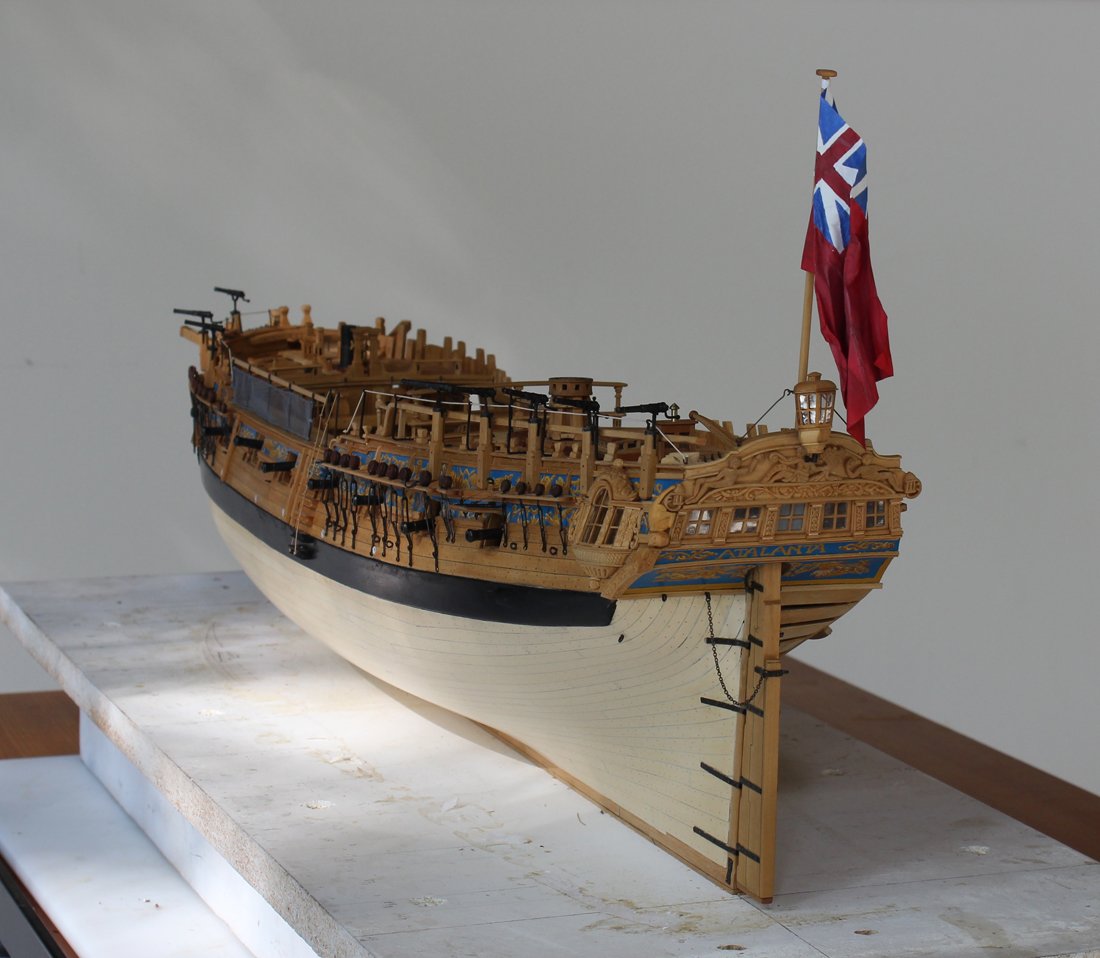


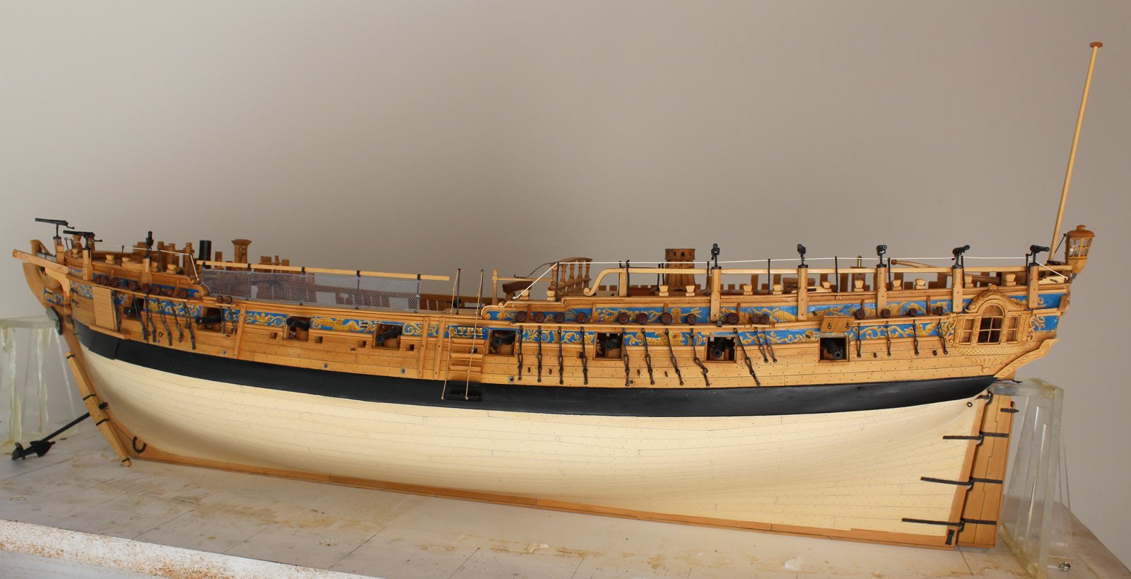


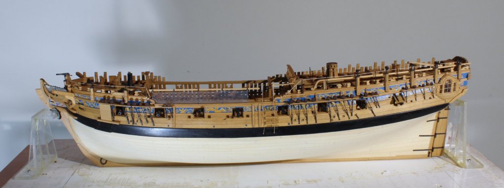
HMS Atalanta 1775 by tlevine - FINISHED - 1:48 scale - from TFFM plans
in - Build logs for subjects built 1751 - 1800
Posted
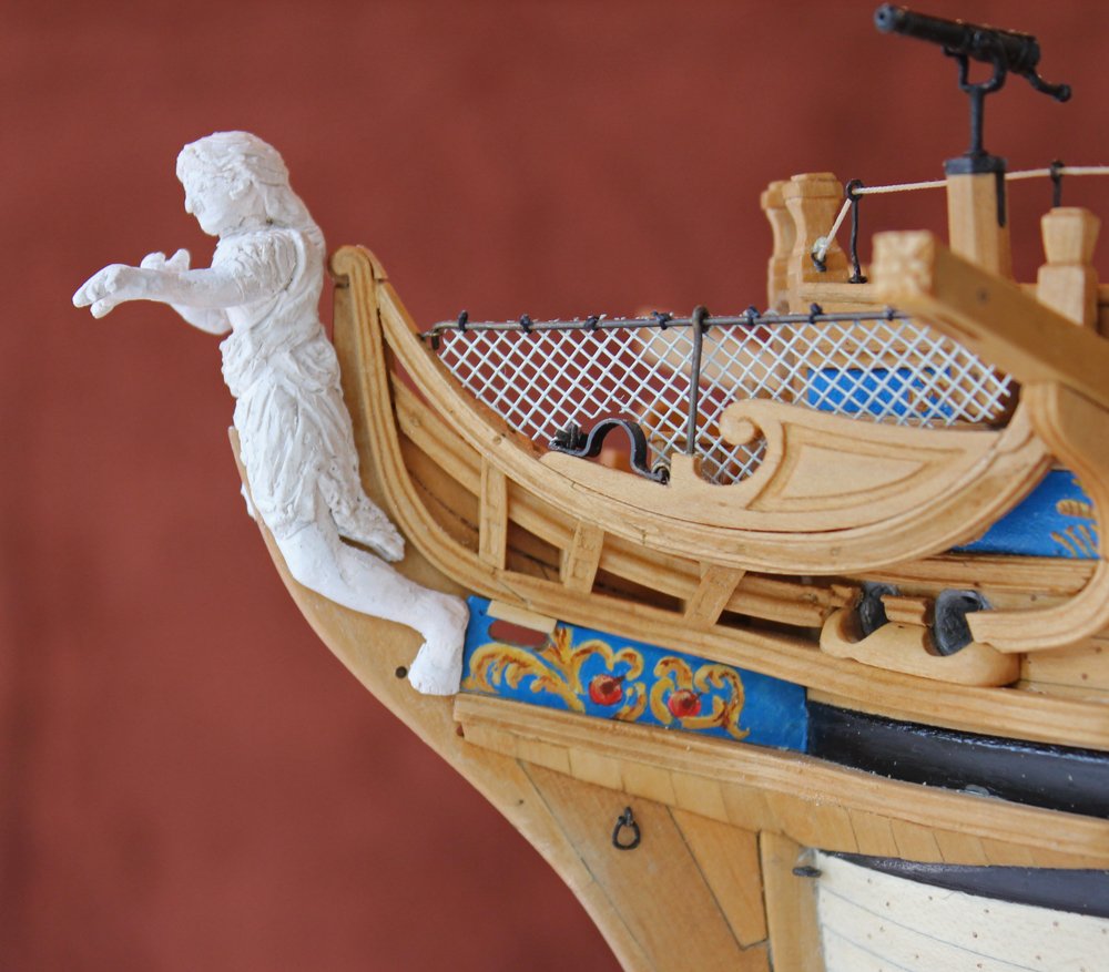
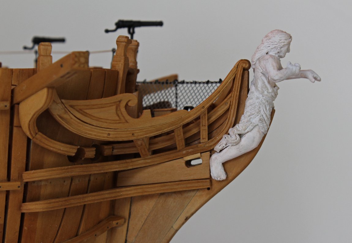
Gentlemen, I appreciate all of your observations. Although she still looks a little clunky compared with the masters on this site like Doris, it is the best I can do. I promise you that I am a much better surgeon than a sculptress. I have lowered the figurehead, making sure the bowsprit clears the top of her head. I have also re-positioned her so that she looks to the horizon. I started painting with a coat of acrylic gray primer. The clay soaks up the paint and this helped seal it. The rest of the painting was done with various acrylic paints. The apple and the buttons on her skirt are gold leaf.
At this point all that remains is cleaning the ship, touching up the black paint on the wale and installing a base. I do not plan on masting and rigging her.