HOLIDAY DONATION DRIVE - SUPPORT MSW - DO YOUR PART TO KEEP THIS GREAT FORUM GOING! (Only 44 donations so far out of 49,000 members - C'mon guys!)
×


BANYAN
-
Posts
5,938 -
Joined
-
Last visited
Content Type
Profiles
Forums
Gallery
Events
Everything posted by BANYAN
-
 Busy little bee then Sjors? and a 'honey' of a result (sorry couldn't help myself cheers Pat
 -
Thanks for looking in and commenting Greg and Don - rapidly approaching that point Greg But, I do need to add the rope coils and two further rigging lines as a minimum - and as I have ordered the Ensign, at least that also. The other two boats - I am debating these cheers Pat
- 517 replies
-
- 4
-

-
- Endeavour
- Artesania Latina
- (and 1 more)
-
Thanks mate - just taken a long time getting there
- 517 replies
-
- 1
-
-
- Endeavour
- Artesania Latina
- (and 1 more)
-
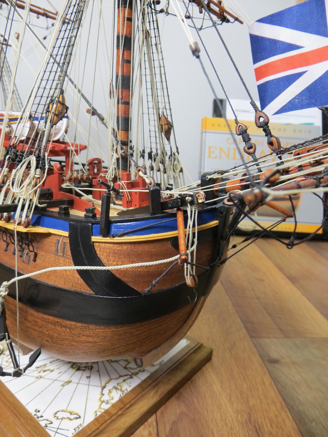
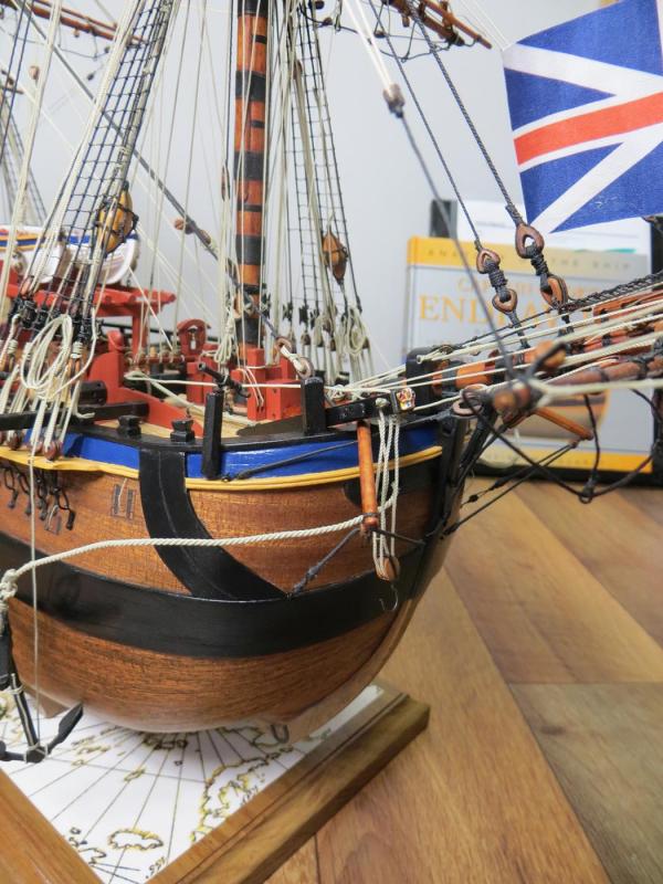
Thanks for all the likes and comments guys - much appreciated. c.a. - yep, that is a copy of the original chart of the East Coast of Australia as charted by Cook on his voyage of discovery. Denis - thanks for noticing the blocks etc John - welcome back - i was wondering where you had gone as hadn't seen a post for a while (was about to PM you ) Keith, Russ and Dave - thanks for looking in and the encouraging comments (see you at the next meeting Keith?) cheers Pat
- 517 replies
-
- 3
-
-
- Endeavour
- Artesania Latina
- (and 1 more)
-
That's a really nice model Dave; great work (and well worth enjoying ) cheers Pat
- 962 replies
-
- 7
-
-
- sovereign of the seas
- ship of the line
- (and 1 more)
-
Even from these preliminary stages, it looks like this will be another finely detailed model Greg. cheers Pat
-
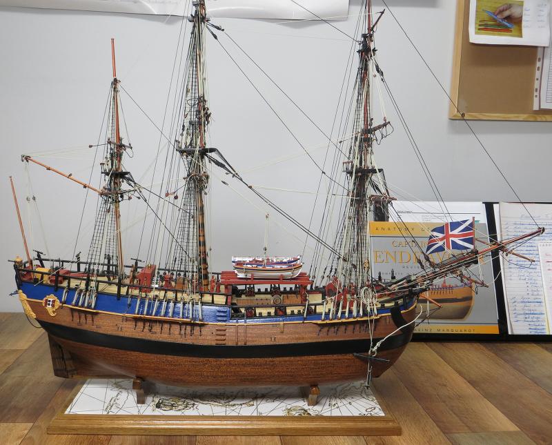
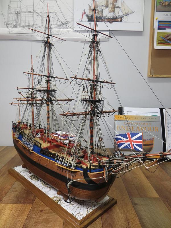
Slowly coming together - these are the latest progress photos. Apart from 2 bunt lines to do on the foremast topsail yard, I have many (NO - very many) coils to make up and place, add the Ensign (waiting for it to arrive), finish the spare yards, 2 x mast tackles (showing them in use), add some boat details (oars etc), make the skiff and yawl and lastly - enjoy cheers Pat
- 517 replies
-
- 14
-
-
- Endeavour
- Artesania Latina
- (and 1 more)
-
Very nice clean work Mark; that mill jig looks quite useful for several purposes other than profiling also. The waterways look good in-situ and the careful marking out and the plank profiles will add a lot of very nice detail. cheers Pat
-
Hi Greg, have edited my post to remove the ref completely Sorry mate, rereading I hope you didn't think I was preaching terminology re "sponsons" - it wasn't intentional and simply automatic for me to use this terminology with my background. cheers Pat
-
Looks good Greg, those sponson supports have a lot of detail for such small items. cheers Pat
-
That is one very detailed kit Greg; how frustrating it must be to drill and assemble all those individual stanchions. cheers Pat
-
Just took a flit through your build OC and the level of detail you are adding is impressive - very nice model developing here. cheers Pat
-
Nice work and some good progress Alan cheers Pat
-
Nice progress Mark - better do it mate - no arguing with she whom must be obeyed cheers Pat
-
Great to hear you are in good spirits and recovering - stretch those "fuss" days out as much as you can mate; doesn't happen too often cheers Pat
-
Some seriously nice PE detail there Greg; wonder you didn't go cross-eyed doing those porthole deadlights though cheers Pat
-
What would modelling be without these mishaps Sjors? As long as you see the positive side of it, it becomes a learning experience Great that Deagostini have supported their product like this. cheers Pat
-
Made my day, great joinery and workmanship as usual Alex cheers Pat