Chuck Posted March 18, 2021 Author Share #961 Posted March 18, 2021 Casting sets are in stock.....but you cant order a figurehead separately. You need to buy the whole set so I dont have to break up sets. FrankWouts and Vladimir_Wairoa 2 Chuck Passaro - MSW Admin Sloop Speedwell - POF scratch Block Island Boat - POF scratch HMS Winchelsea - POB scratch build HM Cutter Cheerful - POB scratch build Royal Barge - POF scratch Medway Longboat- POF Scratch SYREN SHIP MODEL COMPANY Link to comment Share on other sites More sharing options...
Chuck Posted March 18, 2021 Author Share #962 Posted March 18, 2021 Someone mentioned deck beams earlier. I managed to get all of them sanded of char. I will need them as I move forward and thought it best to do them now while building cannon. Some knees will need to be in position to finish the cannon so these are good to have....but it really does change the appearance and gives you a great idea of how she will look. I will number them and remove them until needed. GuntherMT, scrubbyj427, WalrusGuy and 27 others 30 Chuck Passaro - MSW Admin Sloop Speedwell - POF scratch Block Island Boat - POF scratch HMS Winchelsea - POB scratch build HM Cutter Cheerful - POB scratch build Royal Barge - POF scratch Medway Longboat- POF Scratch SYREN SHIP MODEL COMPANY Link to comment Share on other sites More sharing options...
scrubbyj427 Posted March 18, 2021 Share #963 Posted March 18, 2021 Oh this will be exciting! Will we be installing Turned columns to support the beams? Current Builds: HMS Winchelsea 1764 1:48 - 5th rate 32 gun frigate (on hold for now) HMS Portland 1770 Prototype 1:48 - 4th rate 50 gun ship Link to comment Share on other sites More sharing options...
Chuck Posted March 18, 2021 Author Share #964 Posted March 18, 2021 Actually one of the interesting things about the Winnie contemporary model is the columns. All of the columns are square but fancy. Same is true for the uprights on the main rails at the break of the waste. We will be adding them but they wont be round....no lathe needed. Maybe the guy who built this didnt have a lathe either....LOL I love the way this looks actually....see the main rail below. and here is a look at the square uprights on the breast rail for Amazon. This is a better image and how we will make these. Also note the columns holding up the deck beams....you dont see very thick round columns here either. Which is what you usually see in kits and more modern models. These are very slender by comparison. Chuck KenW, G.L., KentM and 9 others 12 Chuck Passaro - MSW Admin Sloop Speedwell - POF scratch Block Island Boat - POF scratch HMS Winchelsea - POB scratch build HM Cutter Cheerful - POB scratch build Royal Barge - POF scratch Medway Longboat- POF Scratch SYREN SHIP MODEL COMPANY Link to comment Share on other sites More sharing options...
Jorge Diaz O Posted March 19, 2021 Share #965 Posted March 19, 2021 3 hours ago, Chuck said: En realidad, una de las cosas interesantes del modelo contemporáneo de Winnie son las columnas. Todas las columnas son cuadradas pero elegantes. Lo mismo ocurre con los montantes de los rieles principales en la rotura del desagüe. Los agregaremos, pero no serán redondos ... no se necesita torno. Tal vez el tipo que construyó esto tampoco tenía un torno ... LOL Me encanta cómo se ve esto en realidad ... vea el riel principal a continuación. y aquí hay un vistazo a los montantes cuadrados en el riel del pecho para Amazon. Esta es una mejor imagen y cómo la haremos. También tenga en cuenta las columnas que sostienen las vigas de la plataforma ... aquí tampoco se ven columnas redondas muy gruesas. Que es lo que se suele ver en kits y modelos más modernos. Estos son muy delgados en comparación. Arrojar I think those beams are metal? I had seen that they have hinges at the top to raise them and make maneuvers, I don't know. -HMS Tritón 1/48 1773 en scracht (TERMINADO) -HMS Winchelsea 1/35 1764 full scracht (EN PROYECTO) Link to comment Share on other sites More sharing options...
scrubbyj427 Posted March 19, 2021 Share #966 Posted March 19, 2021 These columns will be fun to make, are you going to take a similar approach to What was done with the bollard timbers? Current Builds: HMS Winchelsea 1764 1:48 - 5th rate 32 gun frigate (on hold for now) HMS Portland 1770 Prototype 1:48 - 4th rate 50 gun ship Link to comment Share on other sites More sharing options...
Chuck Posted March 19, 2021 Author Share #967 Posted March 19, 2021 Probably but we shall see when I get that far.... Chuck Chuck Passaro - MSW Admin Sloop Speedwell - POF scratch Block Island Boat - POF scratch HMS Winchelsea - POB scratch build HM Cutter Cheerful - POB scratch build Royal Barge - POF scratch Medway Longboat- POF Scratch SYREN SHIP MODEL COMPANY Link to comment Share on other sites More sharing options...
Stuntflyer Posted March 19, 2021 Share #968 Posted March 19, 2021 Will the Winnie have a ladder like this one. It looks like it's twisted in order to conform. Mike KentM, Jorge Diaz O, Elijah and 1 other 4 Current build - Sloop Speedwell 1752 (POF) Completed builds - 18 Century Longboat (POB) , HM Cutter Cheerful 1806 (POB), HMS Winchelsea 1764 (POB) Member: Ship Model Society of New Jersey Link to comment Share on other sites More sharing options...
Chuck Posted March 19, 2021 Author Share #969 Posted March 19, 2021 Nope...the winnie gets a flat one.... G.L., Ron Burns, Elijah and 3 others 6 Chuck Passaro - MSW Admin Sloop Speedwell - POF scratch Block Island Boat - POF scratch HMS Winchelsea - POB scratch build HM Cutter Cheerful - POB scratch build Royal Barge - POF scratch Medway Longboat- POF Scratch SYREN SHIP MODEL COMPANY Link to comment Share on other sites More sharing options...
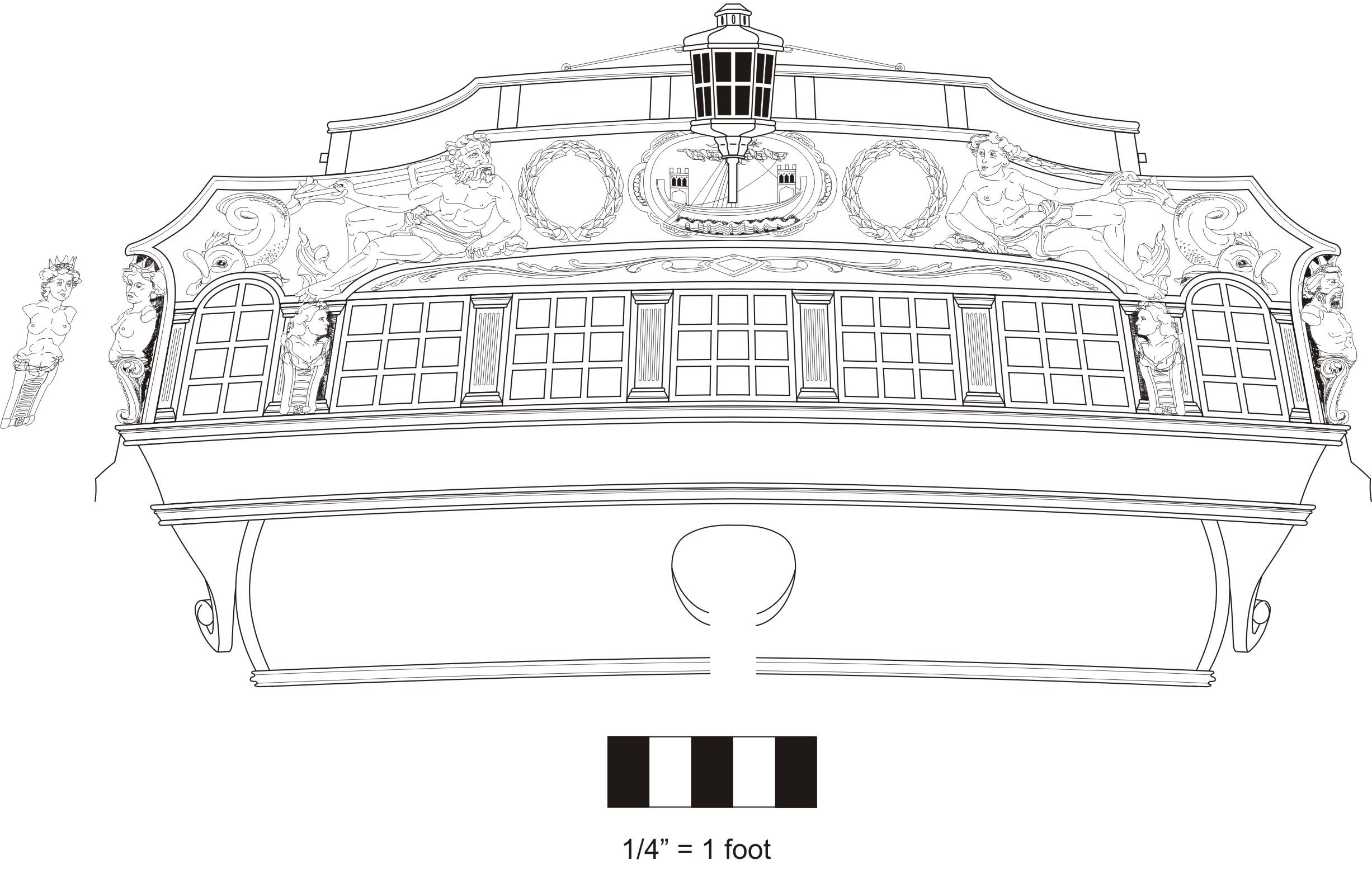
scrubbyj427 Posted March 20, 2021 Share #970 Posted March 20, 2021 Chuck, I’m looking at the drawing in the profile and stern view for the stern lantern and I’m trying to determine exactly how the lantern post will attach, it appears it will land right on the middle of the carving. I am just trying to run my small light before I close up the inner counter. Are you planning on drilling a small hole into the carving to attach the post? JJ KentM, FrankWouts, wyz and 2 others 5 Current Builds: HMS Winchelsea 1764 1:48 - 5th rate 32 gun frigate (on hold for now) HMS Portland 1770 Prototype 1:48 - 4th rate 50 gun ship Link to comment Share on other sites More sharing options...
Chuck Posted March 20, 2021 Author Share #971 Posted March 20, 2021 Yes.....that is how it will work. Just one hole..... Rustyj, FrankWouts, KentM and 2 others 5 Chuck Passaro - MSW Admin Sloop Speedwell - POF scratch Block Island Boat - POF scratch HMS Winchelsea - POB scratch build HM Cutter Cheerful - POB scratch build Royal Barge - POF scratch Medway Longboat- POF Scratch SYREN SHIP MODEL COMPANY Link to comment Share on other sites More sharing options...
Chuck Posted March 24, 2021 Author Share #972 Posted March 24, 2021 Just an FYI Some of you may have noticed that some of the eye bolts on the bulwarks for the gun tackles are in fact secured to a hanging knee. Rather than being secured into the bulwarks. SO.....for chapter six, when we are installing the guns, we will also need to install some of the hanging knees. In order to do this I must prepare the laser cut parts for the deck beams and knees so that you guys can add them. I am working on that now. While waiting for these parts, I must also point out an error I made for the number of hanging knees and lodging knees on the Qdeck. Those many years ago I added hanging knees and lodging knees to all deck beams in the great cabin. This is not correct based on the contemporary model for the Winnie and other primary sources. Its a wonderful thing to have such a detailed example with the Winnie contemporary model. It actually shows all lodging knees..... So I have redrawn and corrected the knee and beam placements. You wont have to print this and could easily use this PDF as a guide for placement of all the knees. See this PDF attached. Its a nice handy reference guide with all knees identified and labeled which will correspond to the laser cut parts when I get them done. I have also added this to the downloads page. beams and knees.pdf Remember these knees are optional.....if you plank the qdeck like this below you wont see any of the knees.....so these laser cut parts will be made available separately along with the deck beams.... This way those who dont want to add them can save a few bucks. Also note the sides of the deck beams painted red....but not all of them. In the partitioned cabins they remain bright. James H, GuntherMT, KentM and 10 others 13 Chuck Passaro - MSW Admin Sloop Speedwell - POF scratch Block Island Boat - POF scratch HMS Winchelsea - POB scratch build HM Cutter Cheerful - POB scratch build Royal Barge - POF scratch Medway Longboat- POF Scratch SYREN SHIP MODEL COMPANY Link to comment Share on other sites More sharing options...
Ron Burns Posted March 24, 2021 Share #973 Posted March 24, 2021 (edited) Thank you for all that Chuck. I can't get over your attention to the finest details. You must have Winnie so dis-assembled and reassembled in your mind that it would blow us normal mortals away just thinking about these things Personally I like the the way she is displayed without them visible but for Winnie II it will be great to have the option. Edited March 24, 2021 by Ron Burns bad formatting as usual FrankWouts 1 Current Build- HMS Winchelsea 1764 1:48 Link to comment Share on other sites More sharing options...
scrubbyj427 Posted March 24, 2021 Share #974 Posted March 24, 2021 Would the real Winnie have had the knees in the cabin? FrankWouts 1 Current Builds: HMS Winchelsea 1764 1:48 - 5th rate 32 gun frigate (on hold for now) HMS Portland 1770 Prototype 1:48 - 4th rate 50 gun ship Link to comment Share on other sites More sharing options...
Chuck Posted March 24, 2021 Author Share #975 Posted March 24, 2021 I dont believe so. Those deck beams were not as long and there wasnt a great weight on that deck with just a few guns and they were small guns also. I have looked and looked for so many contemporary sources. Here is another model where you can clearly see there are no knees back there. Chuck Captain Poison, Jorge Diaz O, Gus M and 9 others 12 Chuck Passaro - MSW Admin Sloop Speedwell - POF scratch Block Island Boat - POF scratch HMS Winchelsea - POB scratch build HM Cutter Cheerful - POB scratch build Royal Barge - POF scratch Medway Longboat- POF Scratch SYREN SHIP MODEL COMPANY Link to comment Share on other sites More sharing options...
scrubbyj427 Posted March 24, 2021 Share #976 Posted March 24, 2021 Ok that makes sense. These will be exciting to put in! Ron Burns and FrankWouts 2 Current Builds: HMS Winchelsea 1764 1:48 - 5th rate 32 gun frigate (on hold for now) HMS Portland 1770 Prototype 1:48 - 4th rate 50 gun ship Link to comment Share on other sites More sharing options...
Chuck Posted March 29, 2021 Author Share #977 Posted March 29, 2021 OK finally the guns are all done.....I just have to make one more eyebolt per gun carriage....for the inhaul. I always forget those until I take pictures. The corresponding eyebolts and split rings were added to the bulwarks. They were made the same as those for the gun carriages. I used 24 gauge black wire. The split rings were the same also using a 41 drill bit to make them. There are also eyebolts/split rings on deck for the carriages which were also made the same. BUT, if you examine the plans there are also 8 larger rings which need to be added. I added those at this time also. Those were made from 22 gauge wire using a #31 drill bit. You can see I forgot the one eyebolt on the back of each carriage....so I will add those at some point. Man that was a lot of eyebolts and split rings to make....sheesh!! Remember that I wont be rigging them so they will look just as you see them here. But the beauty of not rigging them means that I dont have to glue them into position permanently yet. I will wait in case removing them makes it easier to work on the other fittings in the next chapter. But if you are going to rig them....this would be the time. I will rig one just to explain how I do it but then I will take it all apart... Also remember that you wont be able to rig 4 of the guns yet because the eyebolts are actually located in the hanging knees. Those will be added early in the next chapter. So no worries there. Check the plans for those.... And the proverbial pic leaving the camera on deck facing aft showing all the guns....Next up I will rig that one cannon for you folks and start on chapter seven. Ryland Craze, AnobiumPunctatum, archjofo and 42 others 44 1 Chuck Passaro - MSW Admin Sloop Speedwell - POF scratch Block Island Boat - POF scratch HMS Winchelsea - POB scratch build HM Cutter Cheerful - POB scratch build Royal Barge - POF scratch Medway Longboat- POF Scratch SYREN SHIP MODEL COMPANY Link to comment Share on other sites More sharing options...
Gus M Posted March 30, 2021 Share #978 Posted March 30, 2021 oustandin work, impressive Chuck and FrankWouts 2 Greetings Gus ------------------------------------------------------------------- Current build log: San Francisco Cross Section Link to comment Share on other sites More sharing options...
KenW Posted March 30, 2021 Share #979 Posted March 30, 2021 Great work Chuck! I really like that last photo. Cheers. FrankWouts and Chuck 2 Ken NO PIRACY 4 ME! (SUPPORTING CHUCKS' IDEA) Current Build: Washington 1776 Galley Pilot Boat Mary of Norfolk Completed Builds: Continental Boat Providence (from Completed Gallery) (from MSW Build) Continental Ship Independence (from Completed Gallery) (from MSW Build) Rattlesnake (from Completed Gallery) (from MSW Build) Armed Virginia Sloop (from Completed Gallery) Fair American (from Completed Gallery) (from MSW Build Log) Member: Ship Model Society of New Jersey Nautical Research Guild Link to comment Share on other sites More sharing options...
scrubbyj427 Posted March 30, 2021 Share #980 Posted March 30, 2021 Beautiful work Chuck! Chuck and FrankWouts 2 Current Builds: HMS Winchelsea 1764 1:48 - 5th rate 32 gun frigate (on hold for now) HMS Portland 1770 Prototype 1:48 - 4th rate 50 gun ship Link to comment Share on other sites More sharing options...
AnobiumPunctatum Posted March 30, 2021 Share #981 Posted March 30, 2021 It's looking really nice. FrankWouts and Chuck 2 Regards Christian Current build: HM Cutter Alert, 1777; HM Sloop Fly, 1776 - 1/36 On the drawing board: English Ship Sloops Fly, 1776, Comet, 1783 and Aetna, 1776; Naval Cutter Alert, 1777 Paused: HMS Triton, 1771 - 1/48 "Have no fear of perfection - you'll never reach it." Salvador Dali Link to comment Share on other sites More sharing options...
Chuck Posted March 30, 2021 Author Share #982 Posted March 30, 2021 Thank you!!! Chuck FrankWouts and Gus M 2 Chuck Passaro - MSW Admin Sloop Speedwell - POF scratch Block Island Boat - POF scratch HMS Winchelsea - POB scratch build HM Cutter Cheerful - POB scratch build Royal Barge - POF scratch Medway Longboat- POF Scratch SYREN SHIP MODEL COMPANY Link to comment Share on other sites More sharing options...
fnkershner Posted March 30, 2021 Share #983 Posted March 30, 2021 So here is the problem. When Chuck does it it looks so outstanding. I just have to the model myself. But my work never turns out 1/2 as good. I dream of the day when I can take a picture like the above. Chuck, FrankWouts, Rustyj and 2 others 5 Current Builds - 18th Century Longboat, MS Syren Completed Builds - MS Bluenose, Panart BatteStation Cross section, Endevour J Boat Half Hull, Windego Half Hull, R/C T37 Breezing Along, R/C Victoria 32, SolCat 18 On the shelf - Panart San Felipe, Euromodel Ajax, C.Mamoli America, Its a sailor's Life for me! Link to comment Share on other sites More sharing options...
Gahm Posted March 31, 2021 Share #984 Posted March 31, 2021 Outstanding!! Thomas Chuck and FrankWouts 2 Current Built: Model Shipways Syren (US Brig 1803) Last Built: Anfora (kit bashed) Ictineo II (1st steam powered submarine 1864) Link to comment Share on other sites More sharing options...
Chuck Posted April 1, 2021 Author Share #985 Posted April 1, 2021 Thank You guys... I didnt feel like rigging that one gun today but maybe this weekend. So I jumped right into chapter seven instead. I posted this picture earlier as a test for the deck beams. Thats the first step of this chapter. Sand the laser char off the tops of every beam. You dont even have to touch the bottoms of the beams because they will never be seen. You dont want to risk making them too thin. But this pic shows them all in place and left natural. I started at the waist and worked aft and did the same for the fcastle beams. I did this because if I cut one beam too short I could still use it further aft. So work the longest beams first. Cut them to length and test them in their respective slots. Number them as we wont be permanently positioning these for a while. In fact we will be removing them and testing them quite a lot depending on what fittings we are working on at that moment later. Here is an image of the same beams with the front and side faces painted red. This was common practice on those contemporary models. Its up to you. But this will allow you to paint the knees red as well. It will tie everything together nicely. Close up pf the qdeck beams. Notice how I left the beams with the cabin areas bright and natural which was also common practice. One of the benefits of not rigging the guns is they wont get in the way when you start doing other stuff. None of them are glued in yet so I can remove them and also close the port lids so I dont damage them. I want to get that last deck beam in that is up against the transom at the stern. This beam has the round up of the others but also conforms to the curvature of the transom. Its a tricky beam to make. The margin plank will sit on this leaving a rabbet at along the front edge to seat the deck planks in. It is laminated in two layers of laser cut parts. Here are the parts.....or layers. Note that one layer is narrower. This is the bottom layer. These layers were glued together and pre bent at the same time before the glue dried. I used thick slow setting CA for this. Hold the two layers together with the narrow one on the bottom. The forward edge of both layers is flush together. If you bend them slightly to match the round up or camber of the other deck beams ...while the glue sets, it will hold that shape with the camber once dry. It only takes a few seconds so work quickly. You dont have to bend them too much either. There is only a slight round up to these beams. You should do a dry run without glue to see how much pressure to apply to bend them while together. You wont have to apply too much pressure. I applied the CA and while both layers were together....I worked quickly to bend them to the same curve as the other deck beams. Once dry it was tested on the model. Also not that I did carve the notch really wide in the deck clamp because it made testing the beam easier. No worries on the gap you see because that will be covered up in the next step. You can see that I nailed the proper round up needed which can be tested by using a planking strip. Use this across the beams to test how well the plank sits on all of the beams including this last one. If you bent too much its OK....you will be able to bend the other way to lessen the round up. But try not to over bend it so that wont be necessary. Slide that planking strip port to starboard to see how well you did. The aft edge of this beam was also beveled to fit snug against the transom as you can see. This beam isnt glued in permanently yet but it will be very soon. and some pics of Amazon to show you guys again what I am shooting for......or similar. KenW, rafine, Edwardkenway and 23 others 26 Chuck Passaro - MSW Admin Sloop Speedwell - POF scratch Block Island Boat - POF scratch HMS Winchelsea - POB scratch build HM Cutter Cheerful - POB scratch build Royal Barge - POF scratch Medway Longboat- POF Scratch SYREN SHIP MODEL COMPANY Link to comment Share on other sites More sharing options...
Stuntflyer Posted April 1, 2021 Share #986 Posted April 1, 2021 That looks great, Chuck. I was wondering what that last beam was going to look like. Actually it's much wider than I thought. Will you remove it before you paint the inside of the transom? Mike FrankWouts 1 Current build - Sloop Speedwell 1752 (POF) Completed builds - 18 Century Longboat (POB) , HM Cutter Cheerful 1806 (POB), HMS Winchelsea 1764 (POB) Member: Ship Model Society of New Jersey Link to comment Share on other sites More sharing options...
Chuck Posted April 1, 2021 Author Share #987 Posted April 1, 2021 I actually think its a bit wide as well. I am going to make it just a tad narrower...but i will paint the transom after its glued in. There is another board that goes on top which makes the rabbet so i dont have to be so careful. KentM, Stuntflyer and FrankWouts 3 Chuck Passaro - MSW Admin Sloop Speedwell - POF scratch Block Island Boat - POF scratch HMS Winchelsea - POB scratch build HM Cutter Cheerful - POB scratch build Royal Barge - POF scratch Medway Longboat- POF Scratch SYREN SHIP MODEL COMPANY Link to comment Share on other sites More sharing options...
Chuck Posted April 1, 2021 Author Share #988 Posted April 1, 2021 Here it is with the top 3/64" thick layer (margin). See how it creates a rabbet or ledge for the deck planking. The last beam is actually a pretty good width and leaves a nice size ledge for the deck planking. I may leave it as is or just sand it a little. But hopefully this helps you guys visualize how it works. Chuck rafine, Jack H, Edwardkenway and 14 others 16 1 Chuck Passaro - MSW Admin Sloop Speedwell - POF scratch Block Island Boat - POF scratch HMS Winchelsea - POB scratch build HM Cutter Cheerful - POB scratch build Royal Barge - POF scratch Medway Longboat- POF Scratch SYREN SHIP MODEL COMPANY Link to comment Share on other sites More sharing options...
Rustyj Posted April 2, 2021 Share #989 Posted April 2, 2021 This all looks fantastic. I can't wait to get back at her! Chuck, FrankWouts and Jack H 3 Rusty "So Long For Now" Current Builds: Speedwell Completed Build Logs: HMS Winchelsea 1/48 Duchess of Kingston USF Confederacy , US Brig Syren , Triton Cross Section , Bomb Vessel Cross Section, Cutter Cheerful, Queen Anne Barge, Medway Longboat Completed Build Gallery: Brig Syren , 1870 Mississippi Riverboat , 1949 Chris-Craft 19' Runabout Link to comment Share on other sites More sharing options...
Vladimir_Wairoa Posted April 2, 2021 Share #990 Posted April 2, 2021 Watching Chuck ahead chapters is like getting another chapter package for free. so enjoyable. Matt D, Chuck and FrankWouts 3 Link to comment Share on other sites More sharing options...


Recommended Posts