

archjofo
-
Posts
1,397 -
Joined
-
Last visited
Content Type
Profiles
Forums
Gallery
Events
Posts posted by archjofo
-
-
Hello Eberhard,
thanks for the nice comment.
Continuation: For topsail yard - studding sail boom iron
In the meantime I also made the outer studding sail boom irons for the fore topsail yard. Like the inner irons, they were made of brass strips with a width of 1.3 mm and a thickness of 0.25 mm. For brazing with a silver brazing paste I fix the pre-prepared parts on a ceramic plate, as already shown several times.
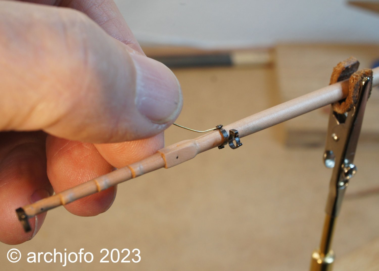
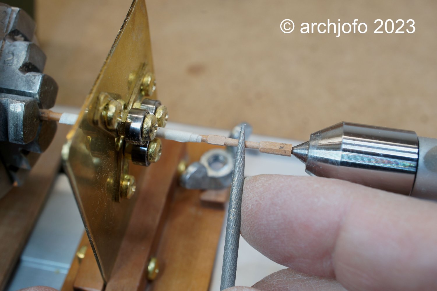
With the following picture I show how the assembly of the inner studding sail boom irons is done. The brass wire ø 0.4 mm, which still has to be shortened, takes over the function of a safety pin.
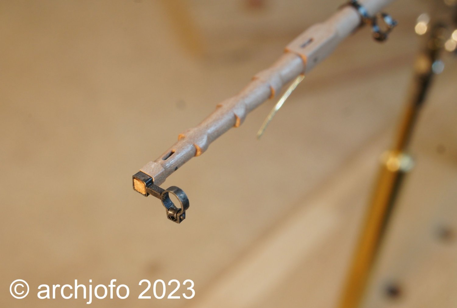
The next picture shows the outer iron of the fore topsail yard. The end of the yardarm is square with dimensions 2.2 / 2.2 mm.
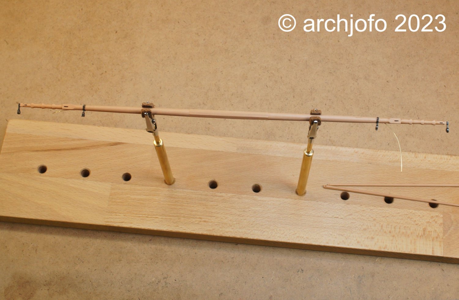
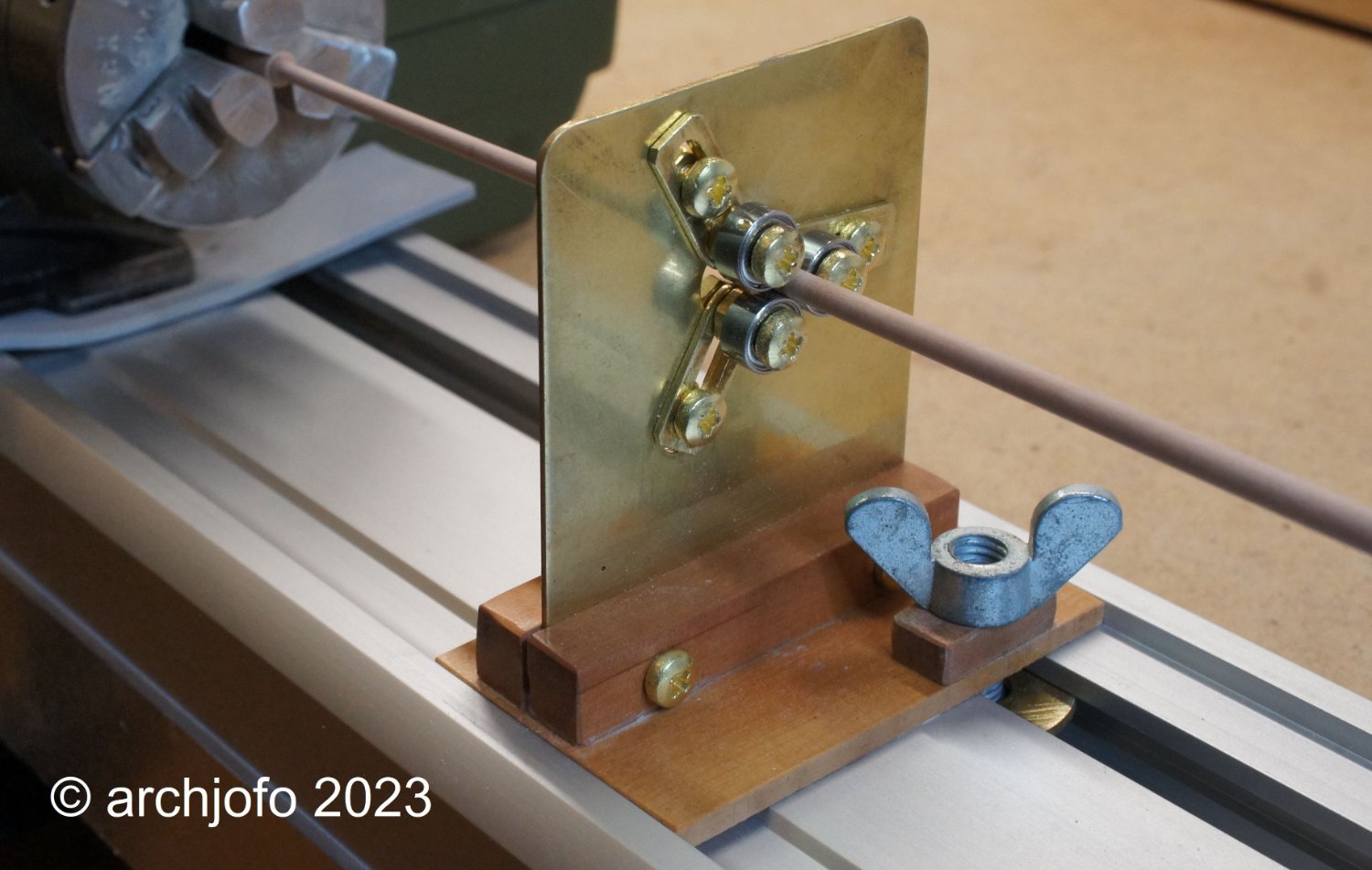
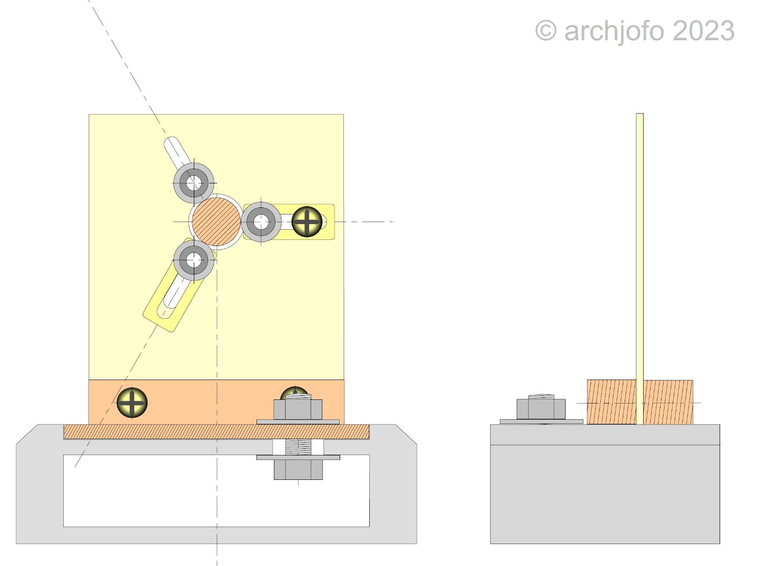
In order to be able to carry out the assembly and rigging work on the yards comfortably, I made myself this holding device.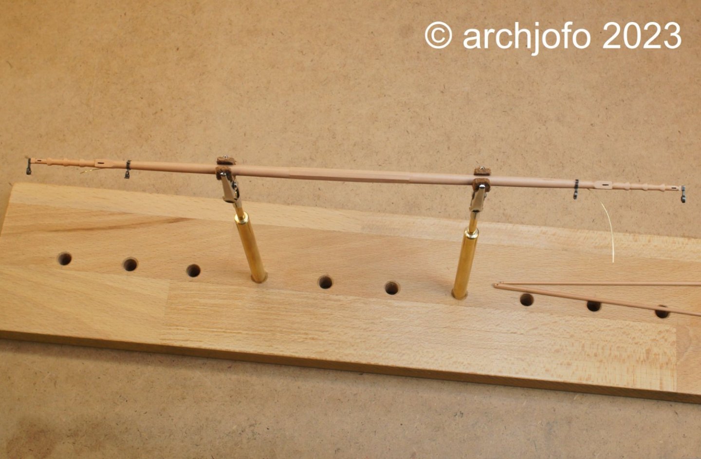
And finally, an overview of the construction status of the fore topsail yard, with the studding sail booms, which in the meantime has each received a hole at the octagonal end. At the outer end, a notch has been added for fastening the blocks.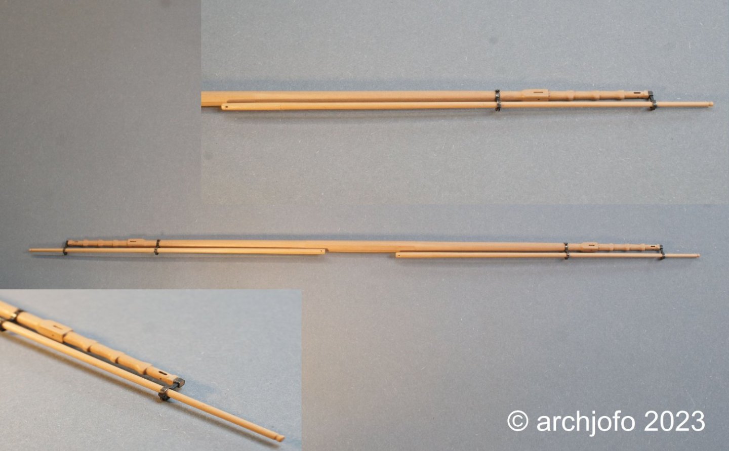
The next step is the studding sail boom irons for the main topsail yard, the dimensions of which are somewhat larger.
To be continued ... -
@druxey
Thanks for your nice comment.
Thanks also to all for the many LIKES.
Continuation: Equipping the yards - studding sail boom irons
After initial problems and a failed attempt, I set out with new courage to make another one. Probably to avoid the mistakes of the first attempt, such as brazing the fine parts of the hinges too much heat, so that they then ultimately become brittle and break off (see picture). In principle, it would also have been possible to make these joints with soft solder. However, for reasons of strength, I chose brazing.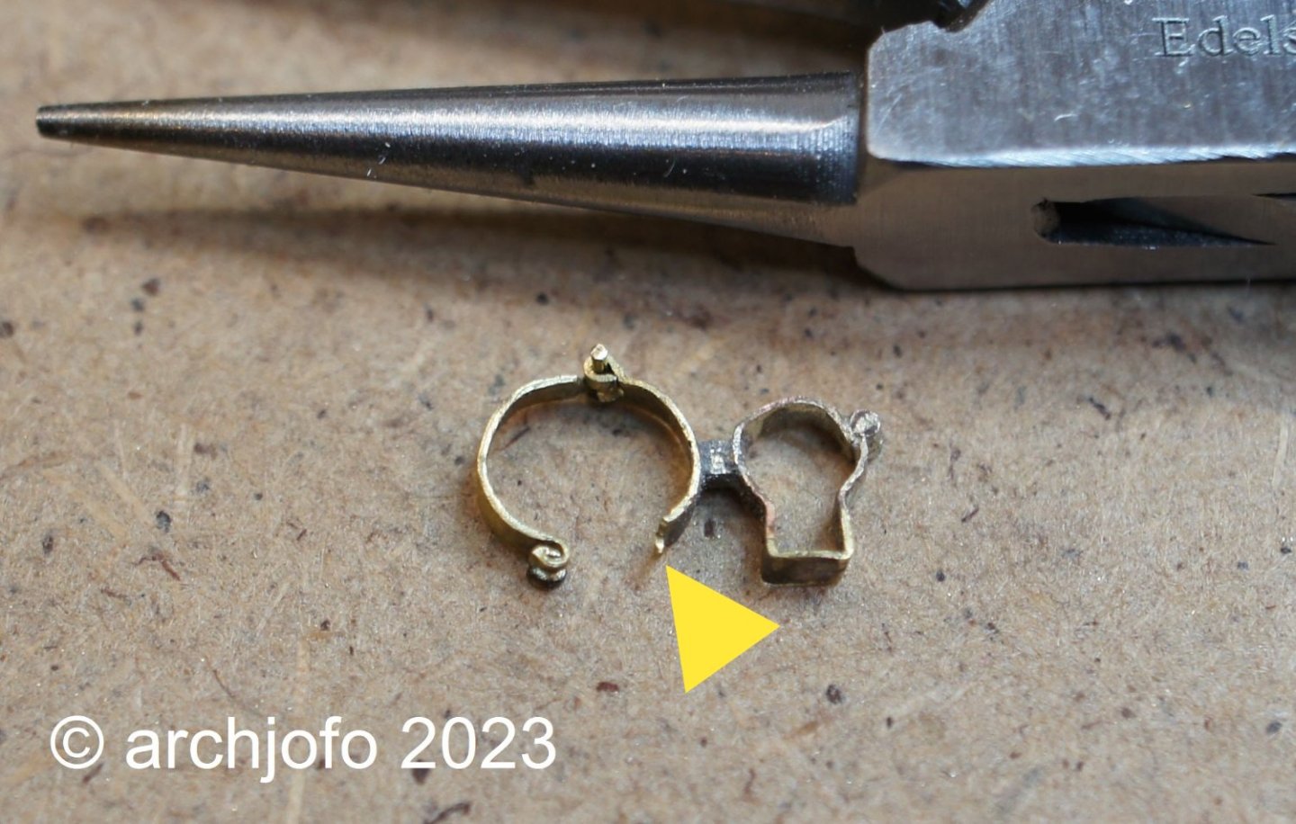
On the next picture I show a photo collage, where single steps for making the studding sail boom iron are shown.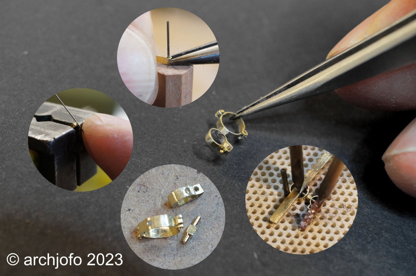
On the next picture you can see the studding sail boom iron still in uncleaned condition after brazing. The outer ring is still missing the hint of a hinge, which I will fix with soft solder.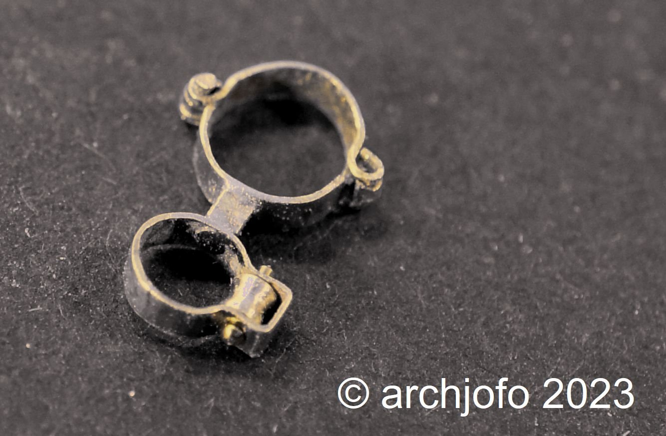
Here a picture with spar: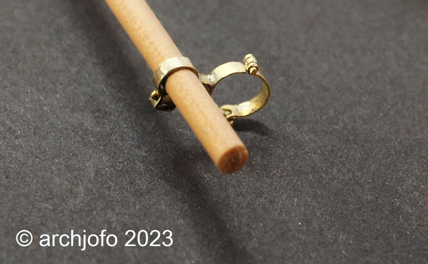
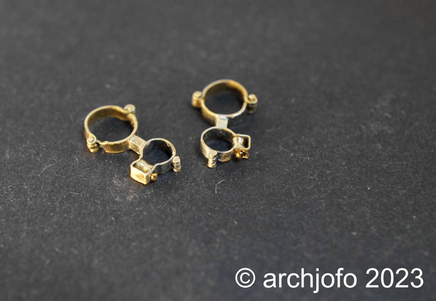
And finally the result for the two inner studding sail boom irons of the fore topsail yard.
Making the outer studding sail boom irons should be much easier.
To be continued ... -
Continuation: Equipping the yards - studding sail boom irons
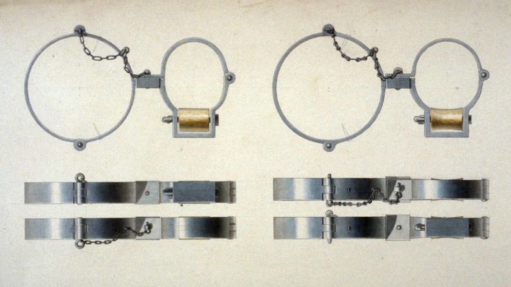
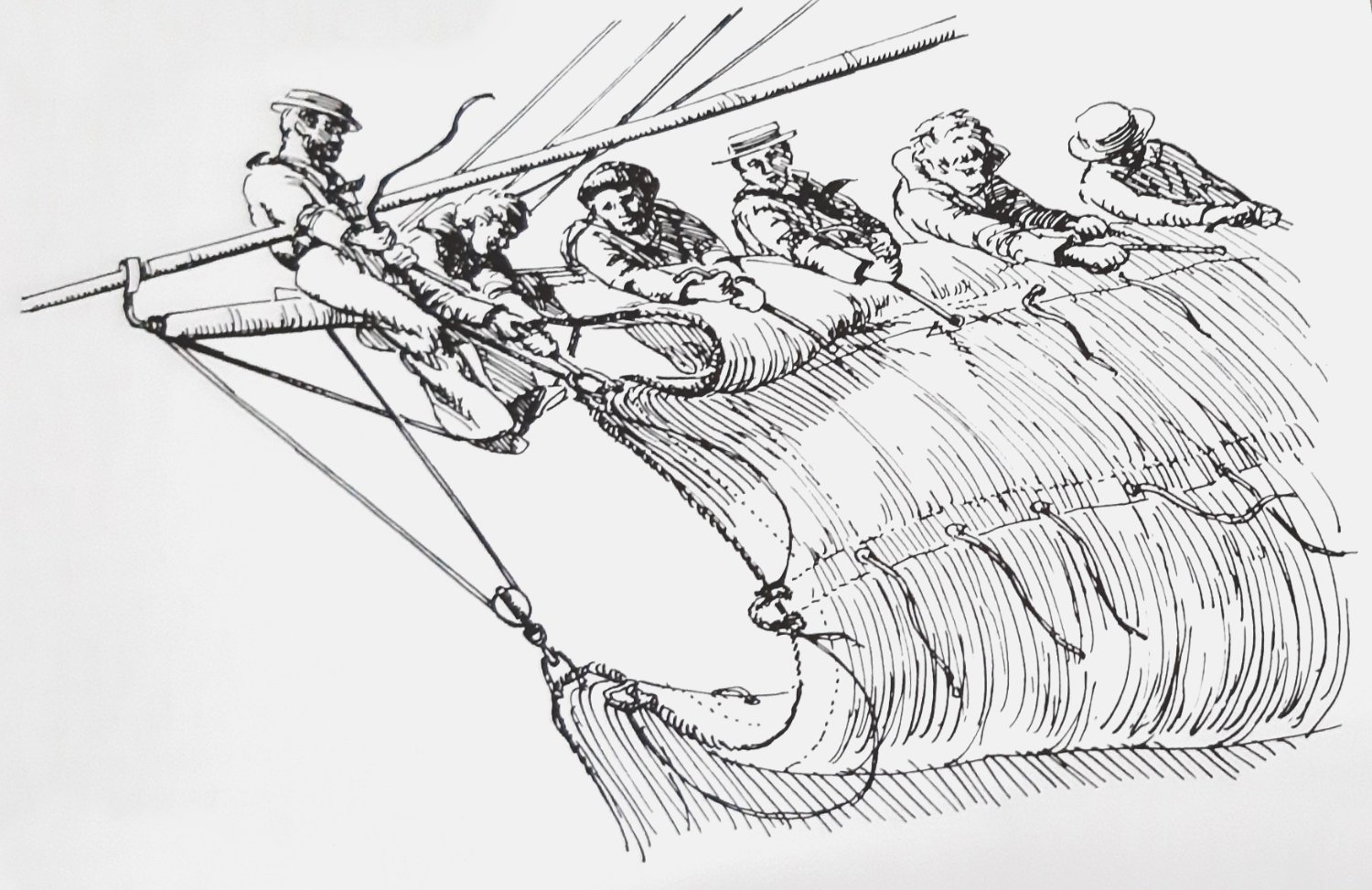
Since I am also interested in how studding sail booms work, that is, how to deploy and attach them, I tried to find more information in the relevant literature and on the Internet. In particular, the book "Seamanship in the Age of Sail" by John Harland describes, among other things, the handling of studding sail booms. This naturally results in various details on the spars themselves (of which later) and in this case on the studding sail boom irons.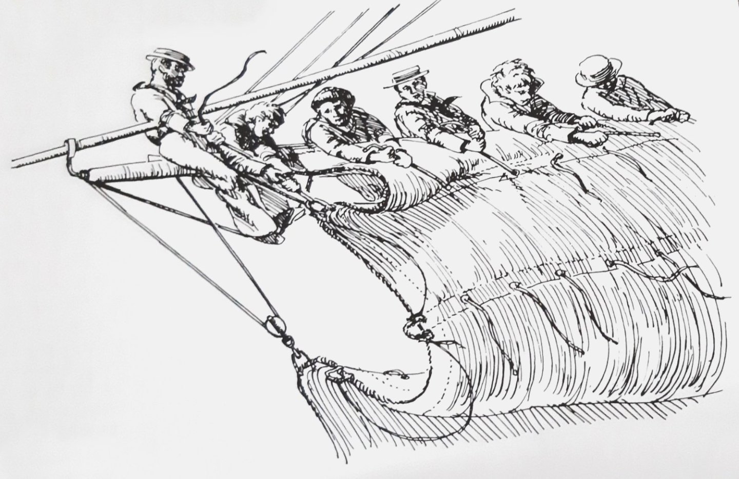
Source: Seamanship in the Age of Sail, John Harland, p. 147The preceding picture from this book explains very impressively that the studding sail booms, which were a handicap when sailing, were taken up and attached to the shrouds. To make this possible, the inside boom irons were hinged to open, which can also be seen in the contemporary drawings below. As can also be seen, these examples have different angles, depending on their chronological placement. This also corresponds with the observations of the photographs of contemporary ship models of the Musée national de la Marine.
Source: Internet_MSW_Archives_G. Delacroix_ca.1830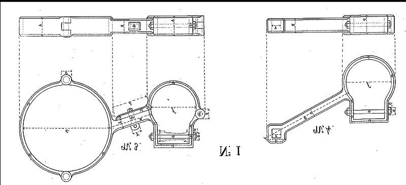
Source: Atlas_Brest_1850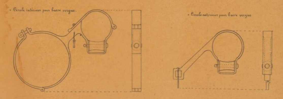
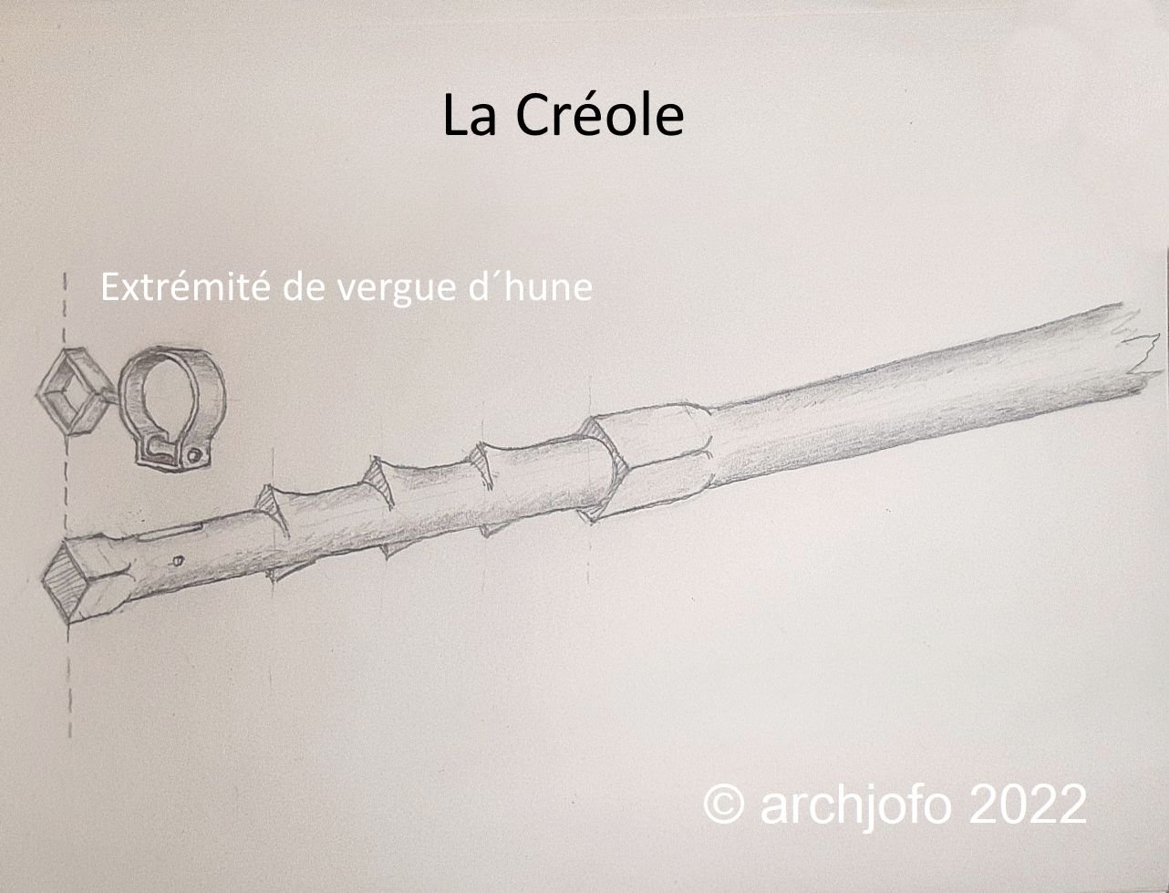
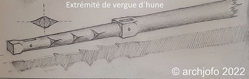
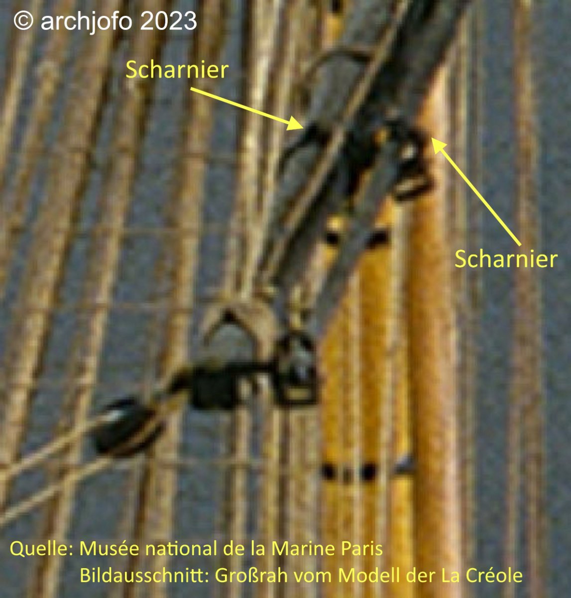
Source: Atlas_Toulon_1854As mentioned before, the Paris Museum has kindly provided me with a high-resolution overall image of La Créole, from which I can obtain additional information to Jean Boudriot's monograph. Especially in the case of the studding sail booms, it can be seen that they were clearly arranged in front of the yard, without angles as shown in the monograph. This also corresponds to the temporal context.
In this respect I orientate myself for my model on the drawing, which I received thankfully from G. Delacroix via MSW. Similarities between this drawing and the original Paris model, as shown below, are clearly recognizable. Also I see there the already described details on the historical drawings confirmed.
Now I will get to work on the realization for the model. I hope to find a way to produce these difficult details as far as possible. A special challenge is the mounting of the inside studding sail boom iron, because I have to choose a two-piece design for it due to the expansions at the yard arms, if possible with hinges like on the original. I have already made comparable hinges for this model as attachment for the front fishes. But this time it has to go one size smaller.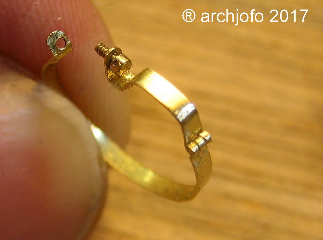
I decided to make the studding sail boom irons for the fore topsail yard first, because they have the smallest dimensions.
Bigger is always possible...More about that soon ...
- JpR62, SIDEWAYS SAM, Wintergreen and 21 others
-
 21
21
-
 3
3
-
Hi Toni,
thank you for your interest in my construction report and the appreciation of my work.
Many thanks also to the others for the many LIKES.
Continued: Equipment of the yards
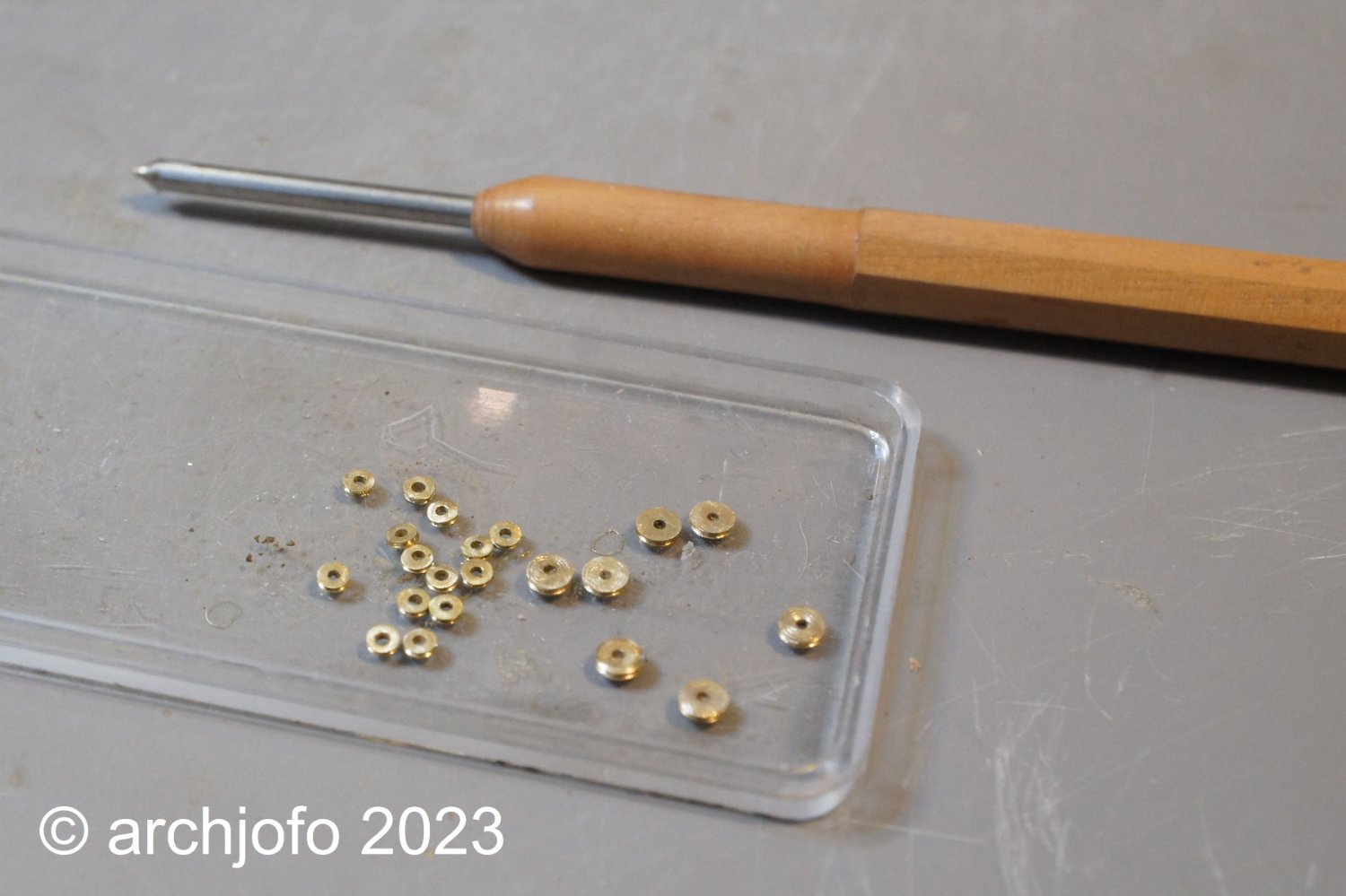
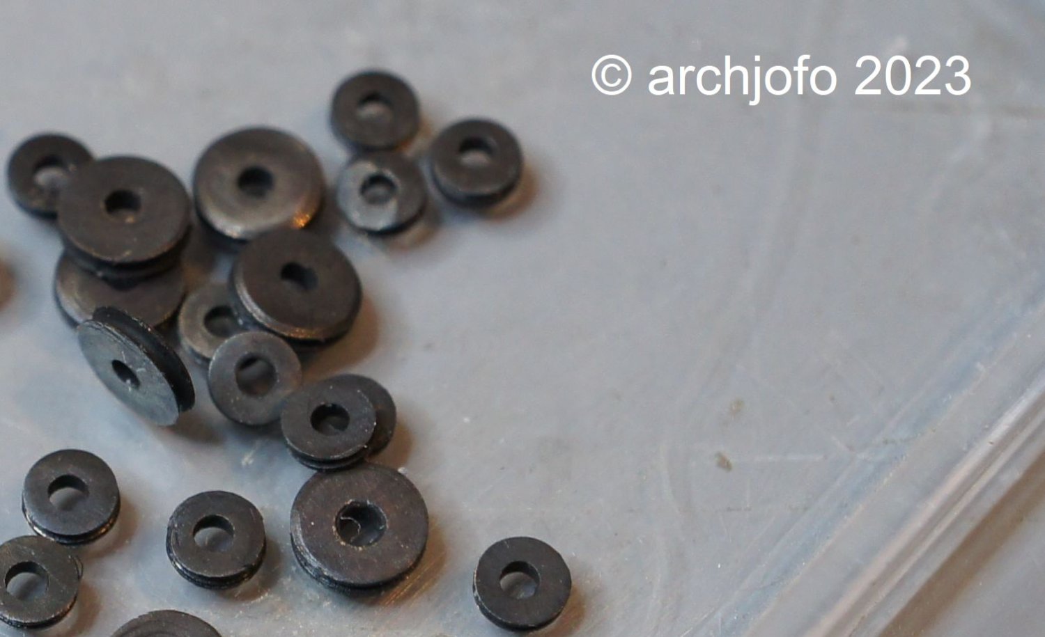
As announced in the last part of my construction report, I equip the larger yards with real discs. As before, I make these discs out of brass and blue them. As far as I know, these discs were usually made of lignum vitae. The rather dark brown coloring of this wood can be easily imitated with a blue finish.
For the main yard and the fore yard, the sheaves have a diameter of 2.9 mm. The main topsail yard, fore topsail yard and mizzen yard are fitted with sheaves with a diameter of 2.0 mm.
With the following series of pictures I would like to illustrate how I make the sheaves. Since my turning skills are limited and with these small diameters, I made the circular groove with a jeweller's saw. The fine saw blade I use for this has a thickness of 0.15 mm. I can control the width of the groove. The more inclined I lead the saw blade, the wider the groove. As a rule, the groove has a width of around 0.2 mm.
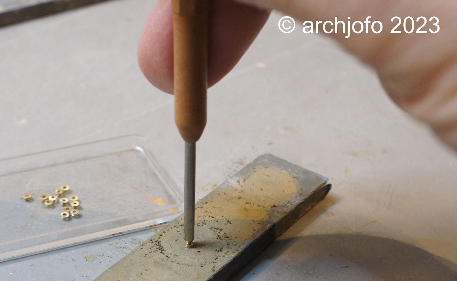
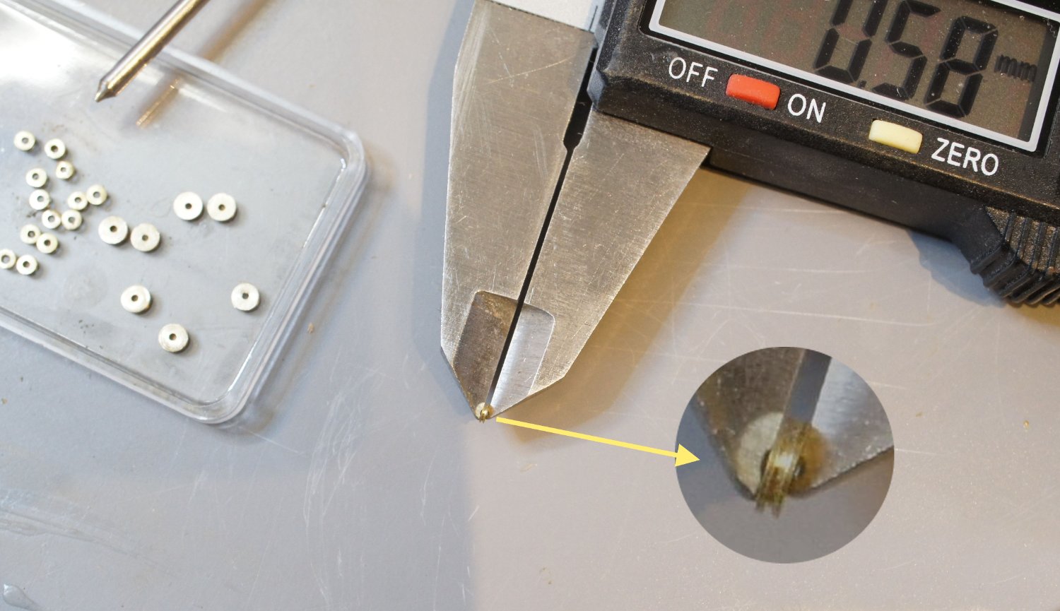
After cutting the sheaves, I grind them to the required thickness according to the size of the protrusion for the sheaves, i. H. about ø 0.6 mm or 0.8 mm. For grinding, I made myself an aid, the tip of which engages in the axle hole and thus enables the sheaves to be guided more or less evenly for grinding.


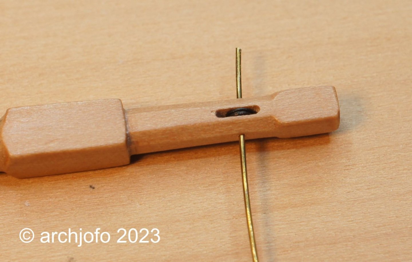
The axle bores of the sheaves were made with ø 0.8 mm larger than the axle diameter ø 0.4 mm itself. This makes the installation of the sheaves much easier and also compensates for small inaccuracies.
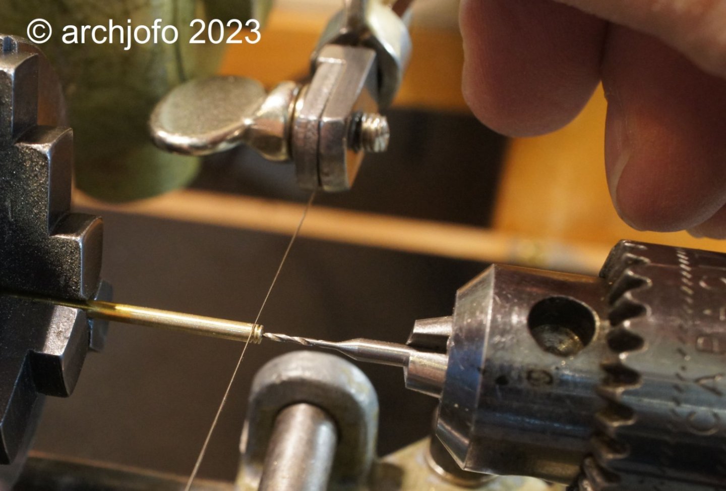
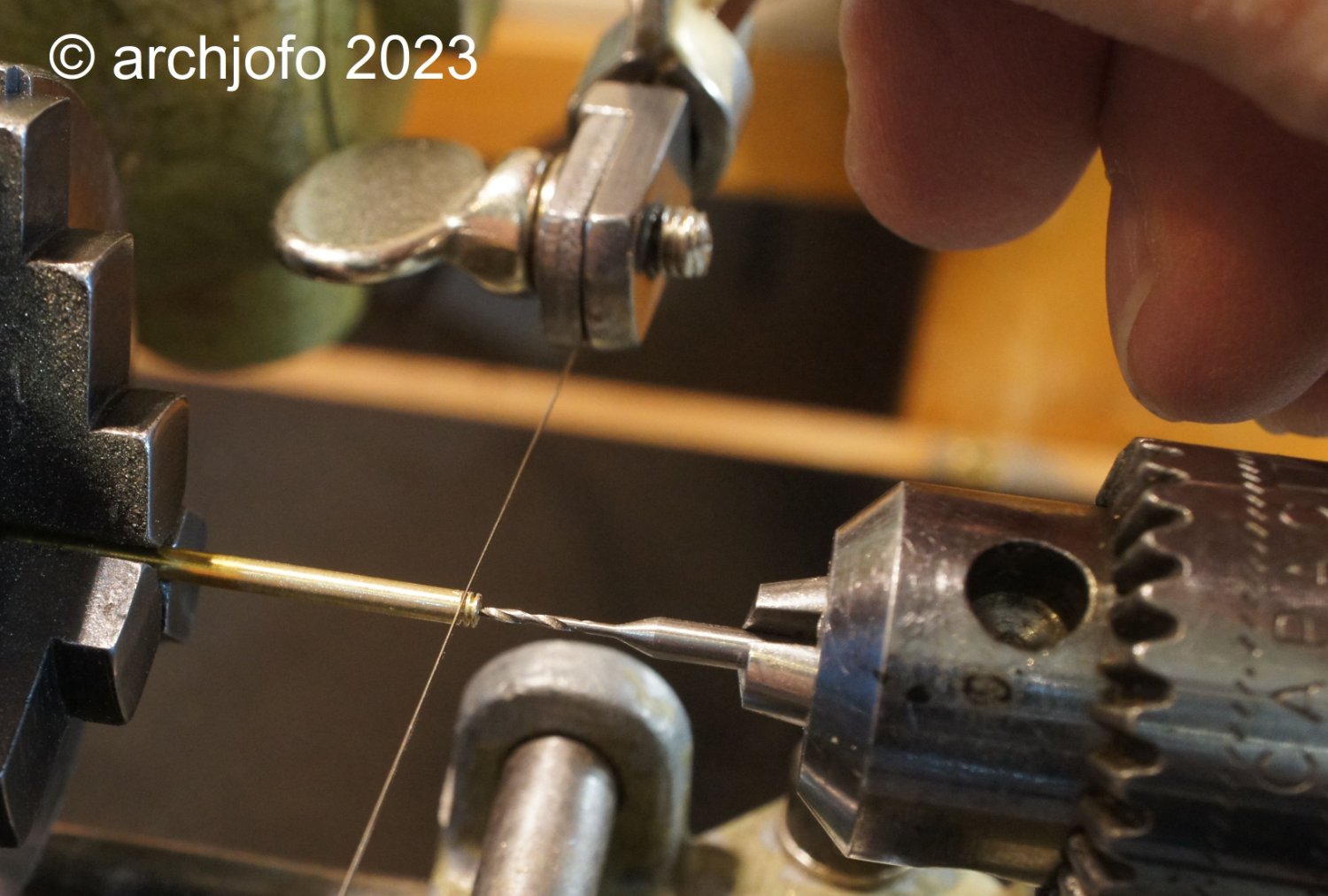
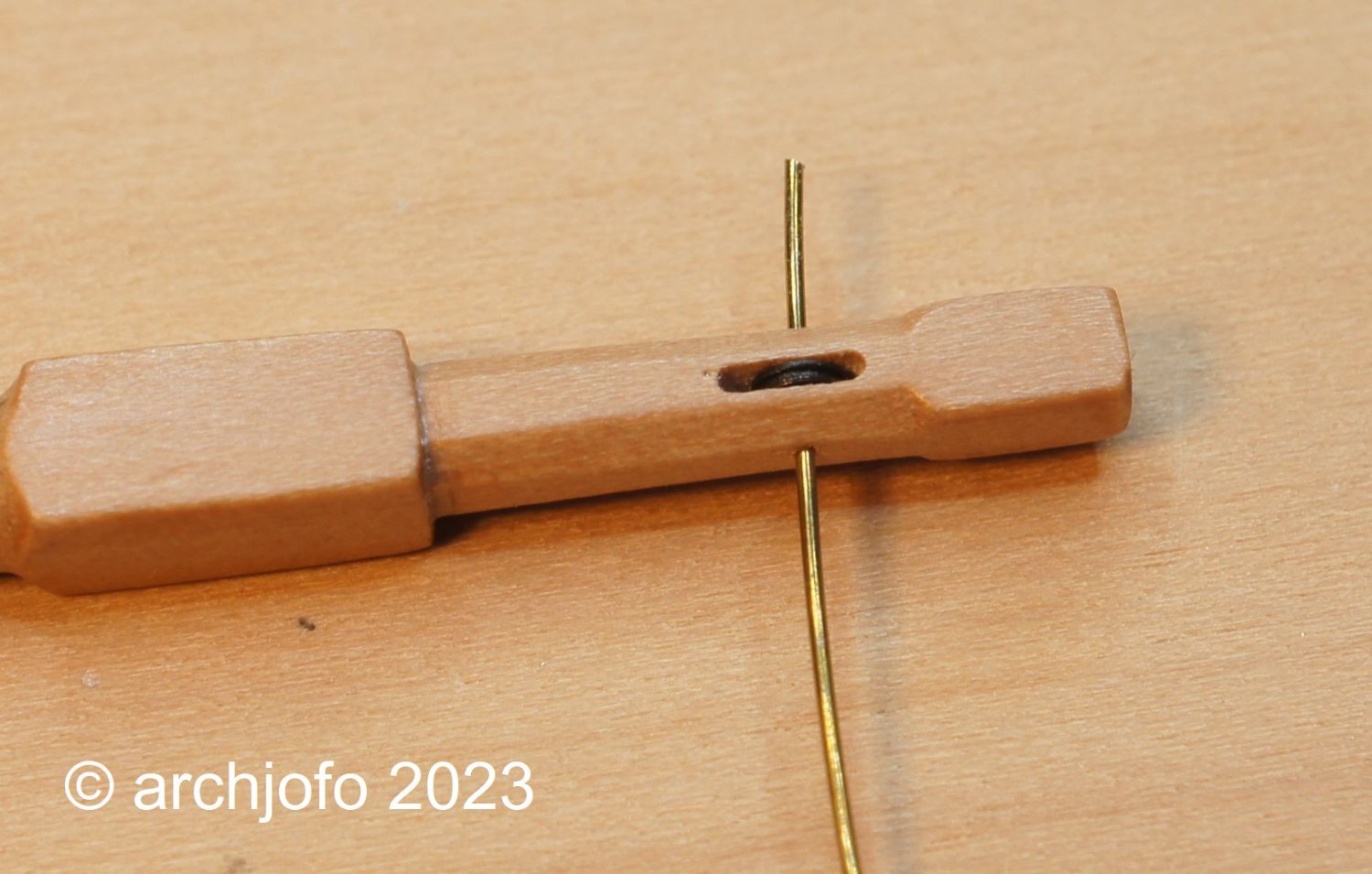
The next pictures should give an impression of the installation of the sheaves. As can be seen in the second picture, the axle holes are not exactly opposite. This is due to the fact that I have to drill the ø 0.4 mm holes for the axles from each side. If you try to drill these holes in one go from one side, it can easily happen that the hole on the other side does not arrive in the middle due to the thin drill and other inaccuracies. This is then much more disturbing than the axis points that are not exactly opposite, which is no longer noticeable after the shortening anyway.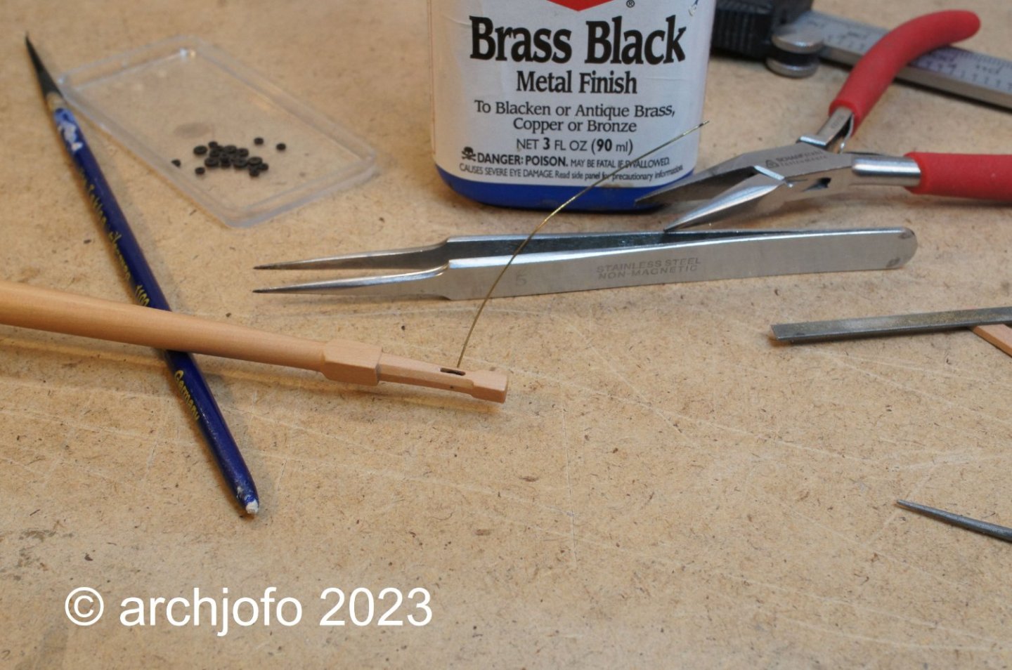
After shortening the axles, the ends are filed clean with a micro file and blued. The filing creates a small burr, which usually makes it no longer necessary to glue the axles.
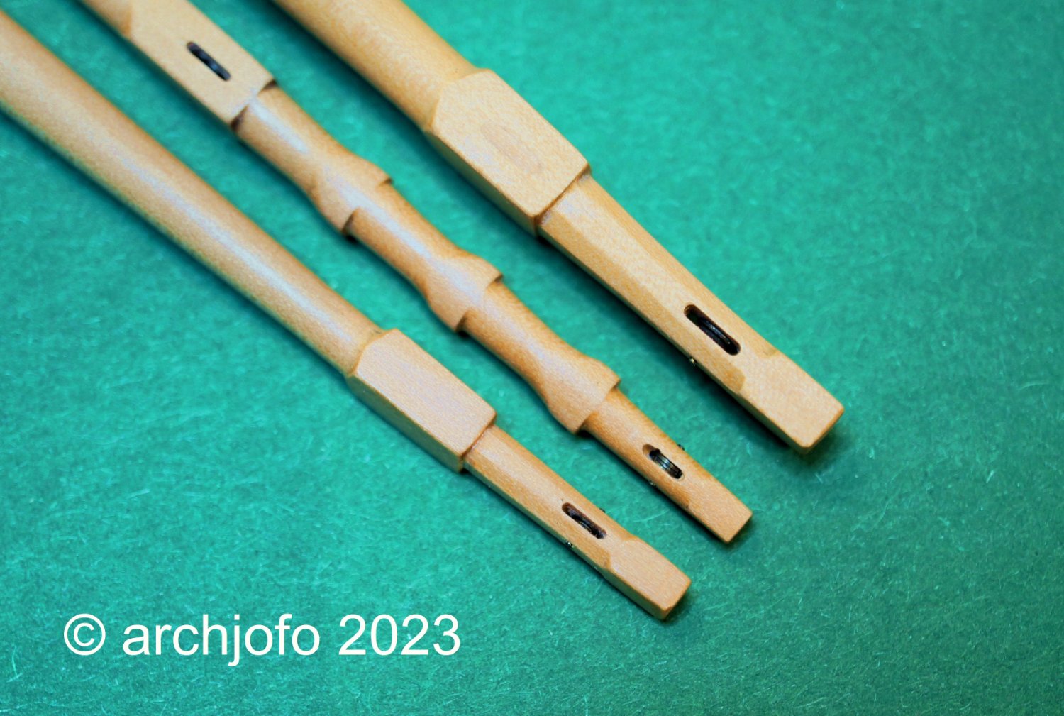
The last picture shows the finished yardarms of the fore yard, main topsail yard and mizzen yard.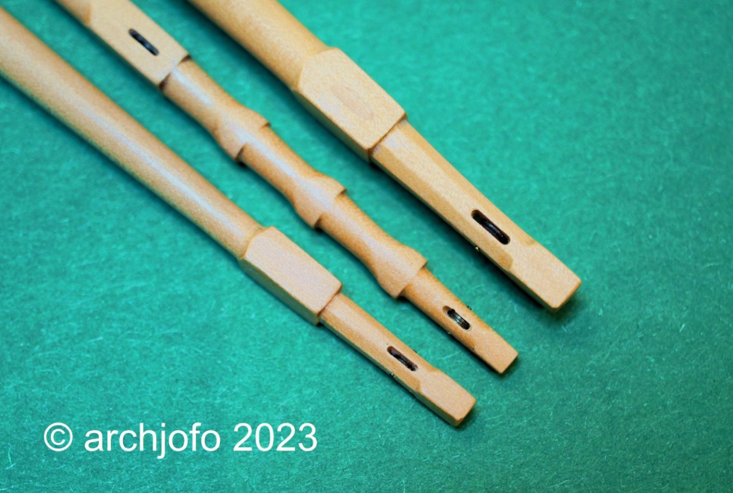
It then continues with the stunsail boom irons. There are still a few open points to be clarified, as always... 😊
Sequel follows …- Paul Le Wol, SIDEWAYS SAM, rybakov and 26 others
-
24
-
5
-
Fantastic work !
- mtaylor, BETAQDAVE, Keith Black and 1 other
-
4
-
Hello,
Thanks for the positive comments, also for the many LIKES.
That motivates even more.
Equipping the yards
In the meantime, I have started to fit the ends of the yards with sheaves, over which the sheets and reef tackles are then passed.
In the lower and topsail yards, the holes for sheave were made with the 0.8 mm and 0.6 mm milling cutter, with the exception of the mizzen topsail yard. Brass turned sheaves will be installed there later.
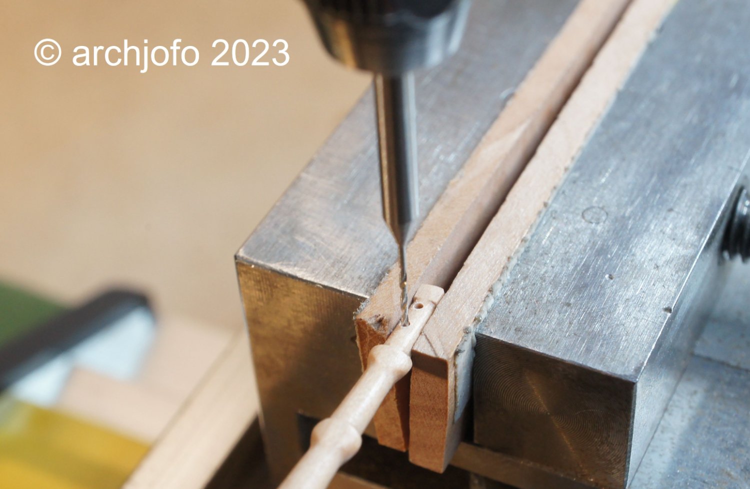
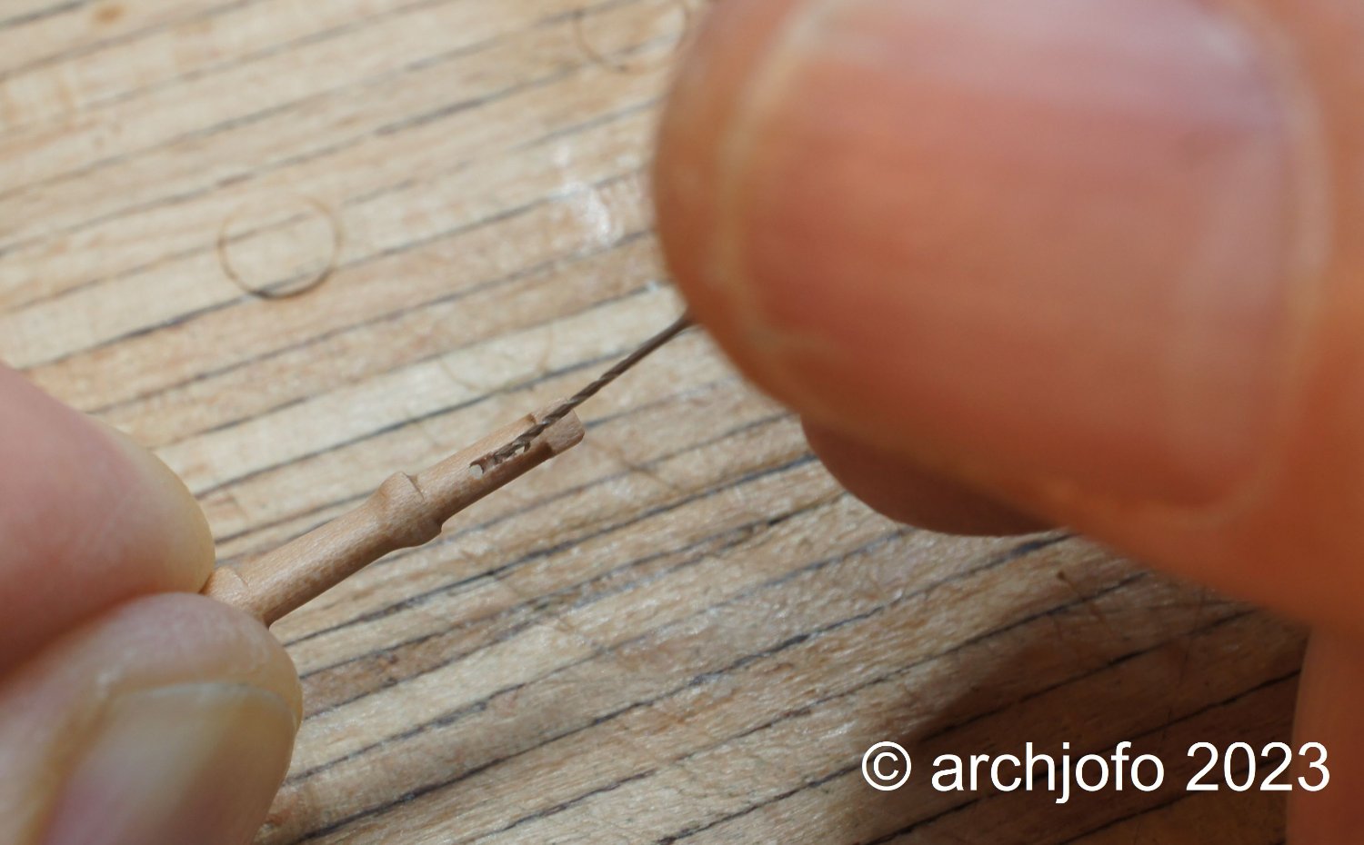
For the topgallant and royal yards with the mizzen topsail yard, the sheaves are only suggested due to the size. The following pictures show the individual processing steps.1. drill holes with 0.5 mm

2. finishing with 0.5 mm wood hollow chisel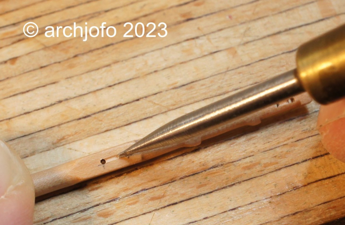
3. rounding out with 0.5 mm shank drill bit

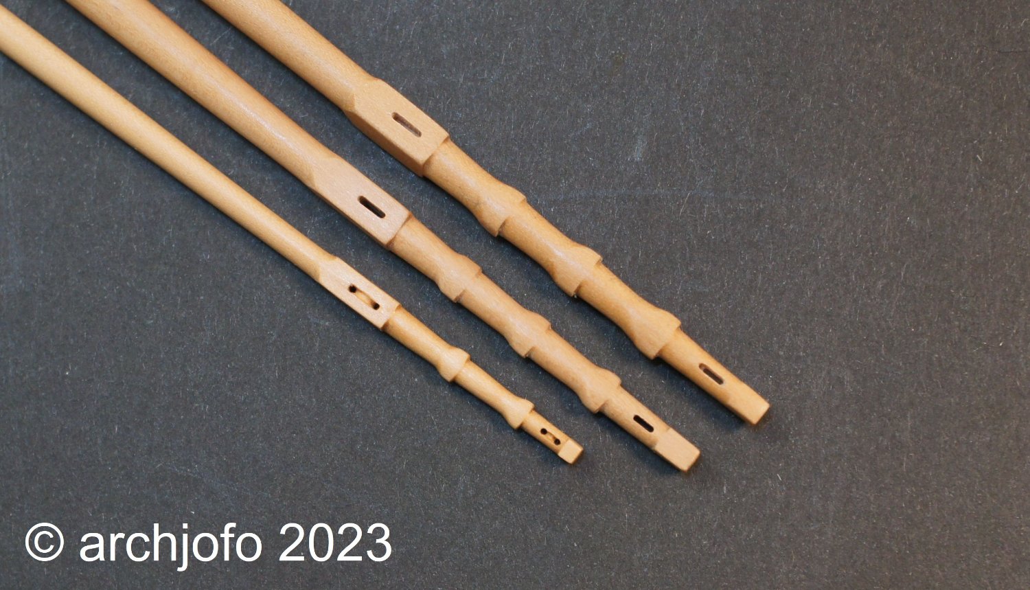
The last picture shows the yard arms of the main topsail, fore topsail and mizzen topsail yard.
I think that the "fake" sheaves in the mizzen topsail yard are reasonably convincing. I have also used the same method on many blocks.
See you soon ...- rybakov, Keith Black, tkay11 and 25 others
-
28
-
Your stove has become a small work of art.
And the preparatory work for the gun carriages again promises very nice guns. I'm really looking forward to that.- mtaylor, matiz and Keith Black
-
3
-
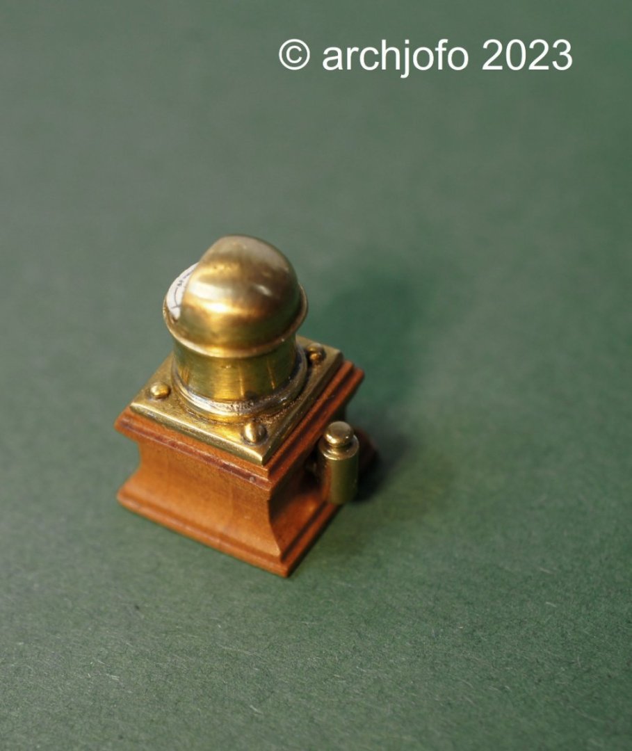
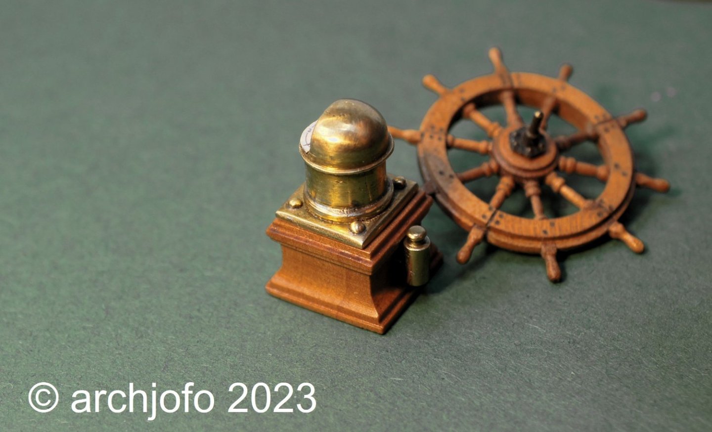
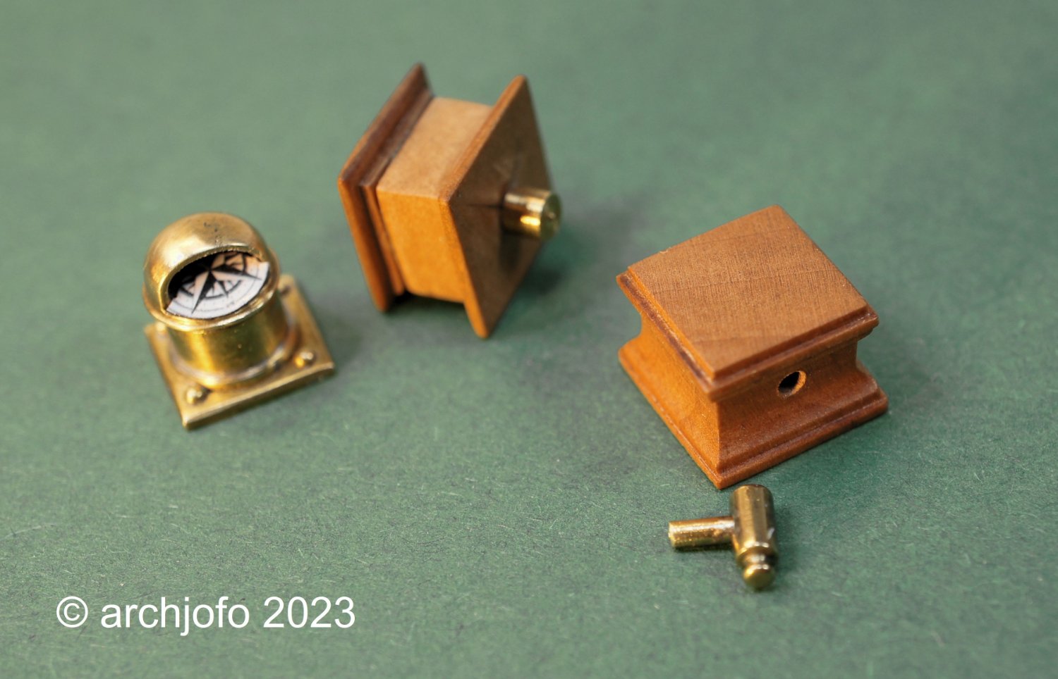
Continued: ship's compass
Some time ago I was concerned with the question of what the part at the back of the binnacle of the La Créole is. There is much to be said for a soft iron corrector, the so-called flinders bar. Lighting would also be conceivable based on the shape. The discussion, including in the MSW, does not yield a clear result. After I got to see historical compass housings in the meantime, where the lighting was arranged below the compass rose, I personally tend to think that this could have been a lamp. Also because of the fact that this corvette was a wooden ship, i.e. had little iron to influence the compass, and on the other hand lighting seems to be quite useful and necessary. In the end I can't say for sure.
So I decided to just build this thing and leave it up to the viewer what he thinks it is.
On this occasion I revised the compass and remade the wooden case. The lamp ? or the soft iron corrector? was made from a round brass rod ø 1.5 mm analogous to the photos of the Paris model available to me.
Sequel follows … -
Hello,
I sand the surface of the spars with 500 grit sandpaper and finish with a fine steel wool.
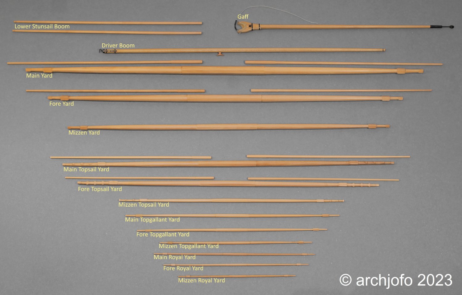
Completion: Yards and spars
With the production of the lower studding sail booms, which are attached to the fore-channels, I could finish the chapter yards/spars for my corvette.
So I had to show all the spars in their entirety, as you can see below:
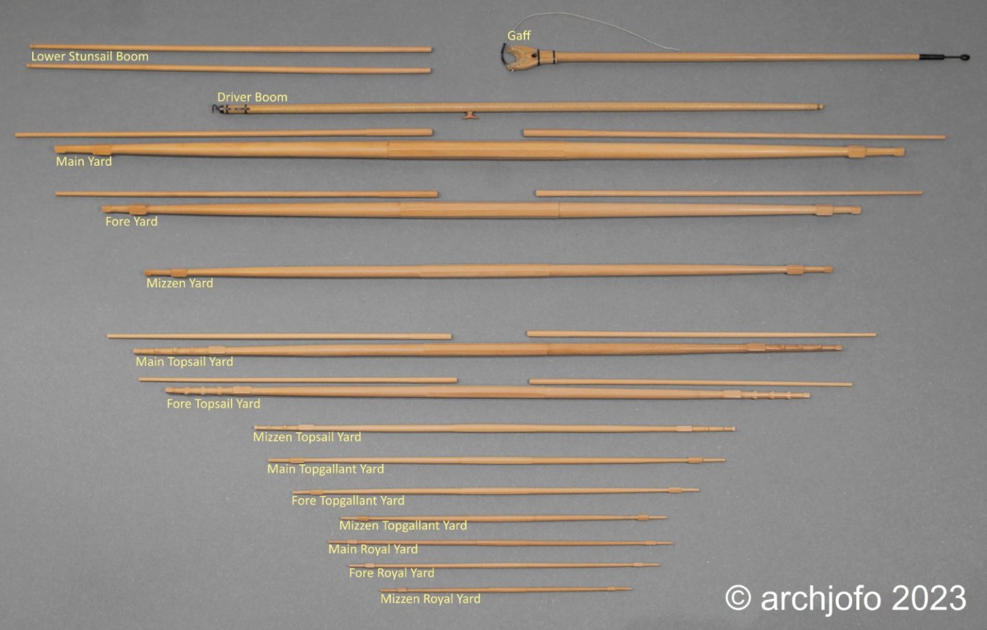
This completes the woodwork on this model except for more blocks and a few odds and ends.
I am currently researching the studding sail boom iron, among other things. Also for this there is a multiplicity of variants, which are to be evaluated and classified chronologically correctly. The monograph of J. Boudriot leaves some questions open.
See you soon ...- JOUFF, Siggi52, Prowler901 and 24 others
-
27
-
-
-
Hello,
thank you for the interest and the good comments, and thank you also the others for the many LIKES.
Continuation: Making the topgallant yards - Vergue de cacatois
In the meantime, I have started making the topgallant yards. As already written in the last report, the topgallant yards are even thinner and more filigree, like the topsail yards.
The dimensions from the plan documents of J. Boudriot were again compared by me with the data of a contemporary original document. This table shows the dimensions of the masts and yards of the La Blonde, which is identical in construction to the La Créole. All dimensions corresponded to the drawings, as is clearly shown in the following drawing.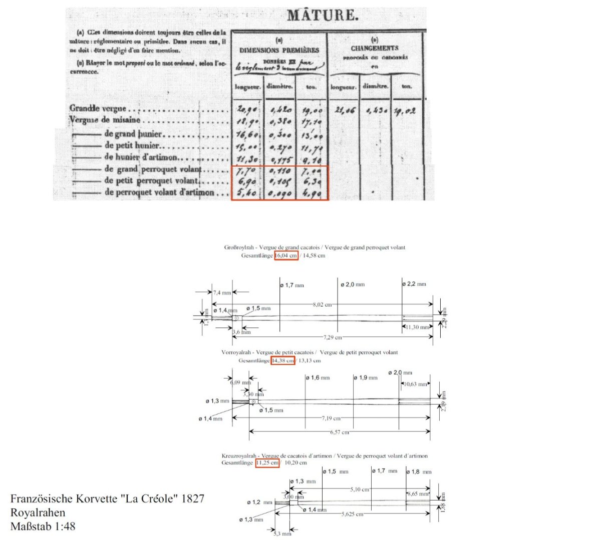
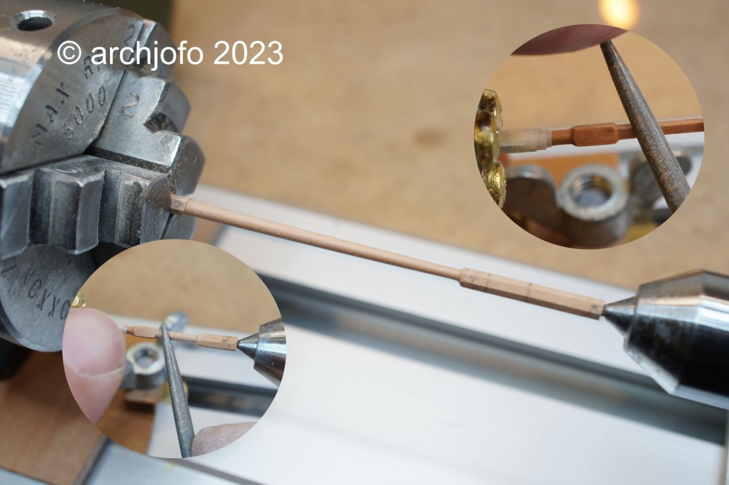
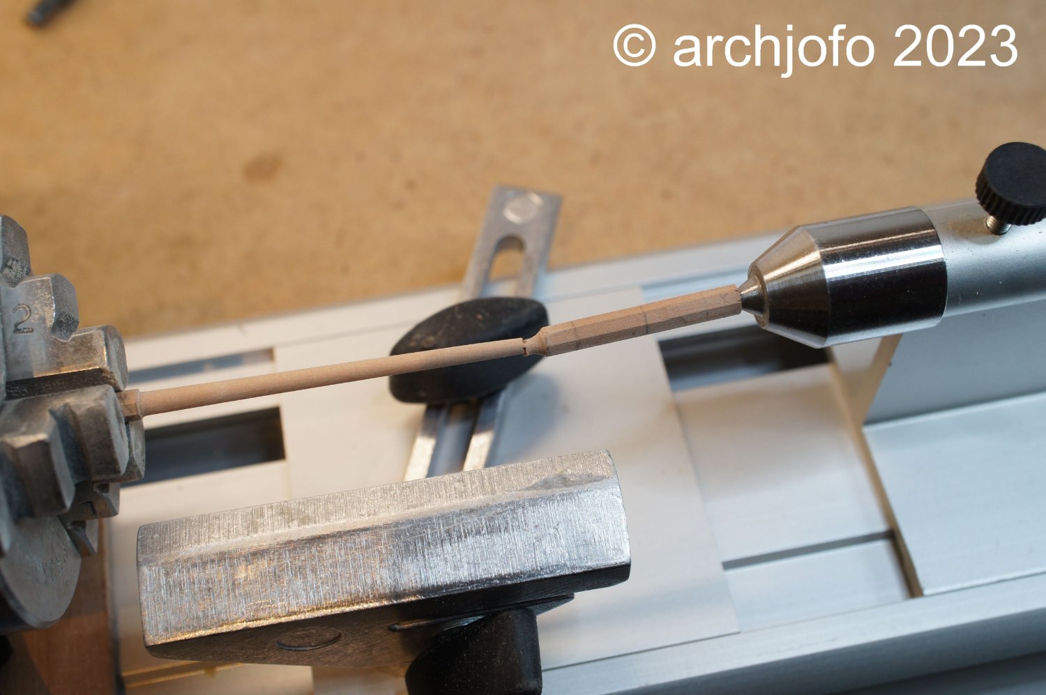
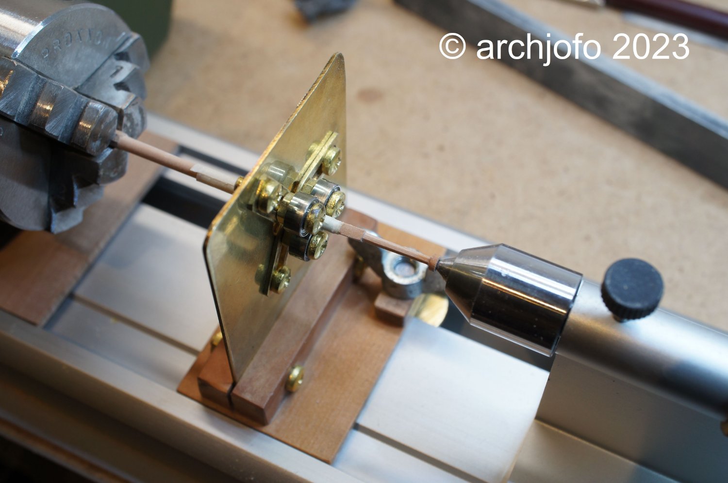
I have already noted that with these dimensions at ø 1.4 mm it is no longer feasible without a steady rest. A toothpick, for example, has a diameter of 1.8 mm. In this respect, particular care should be taken here and not too much pressure should be exerted on the roundwood.
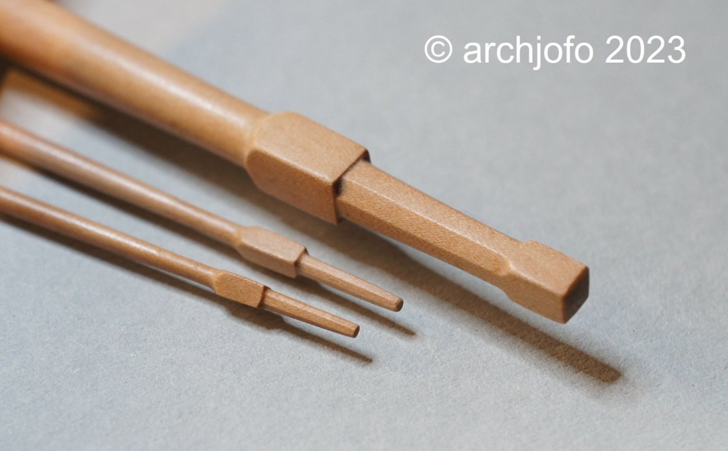
The shaping of the square edge with the octagonal yardarm also requires sensitive processing, which can be seen in the next picture.
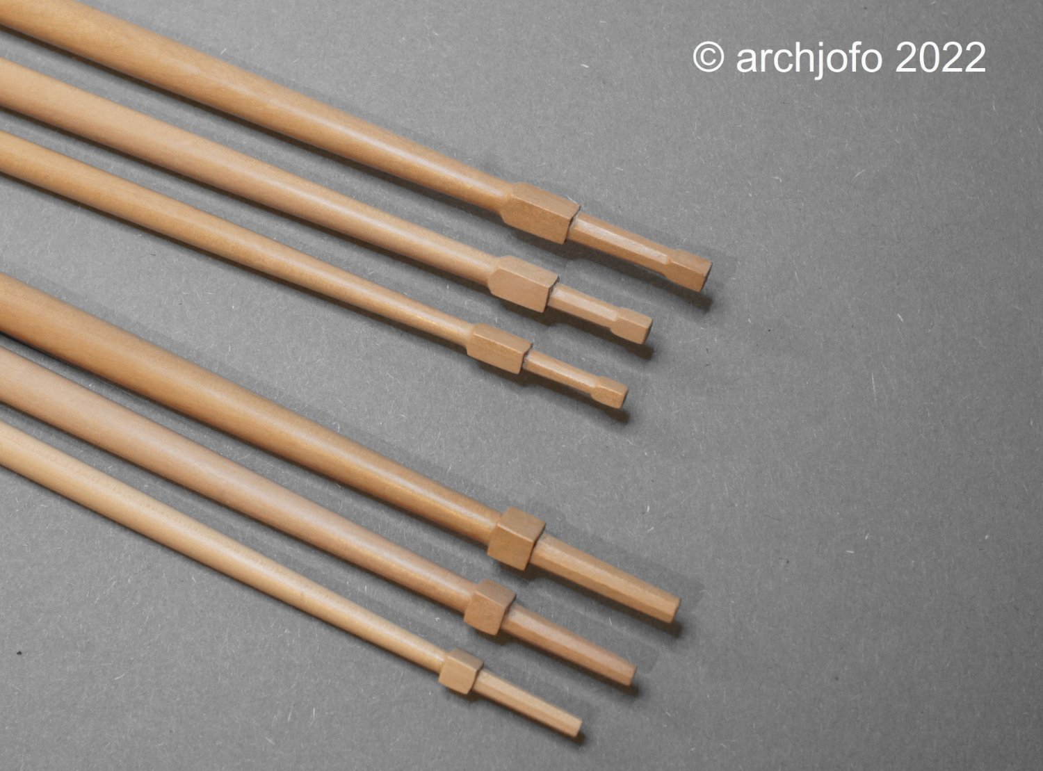
At the end of this work, a comparison of yardarms:Main yard, mizzen toppsail yard and mizzen topgallant yard
Now two lower studding sail booms have to be made to hang on the fore channels.
With the gaff (upper spar) and the driver boom (lower boom) already made some time ago, all the sail-carrying spars for the French corvette are then ready. They will then be equipped with the necessary fittings (sheaves, boom irons, etc.).
To be continued ...
- Wintergreen, GrandpaPhil, No Idea and 22 others
-
21
-
4
-
Continuation: Making the yards - Topgallant yards - Vergue de perroquet
After the topsail yards, we continued with the making of the topgallant yards.
Here is a quick look at my workplace with the most important utensils for making the yards: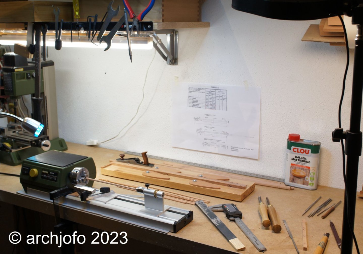
The diameters of the topgallant yards, especially in the outer sections, range around 1.6 mm. In this respect, it is not surprising, if you work without a steady rest, that it can sometimes come to breakage.
At the latest when working on the yardarms, it is advisable to support the filigree yards with a steady rest.
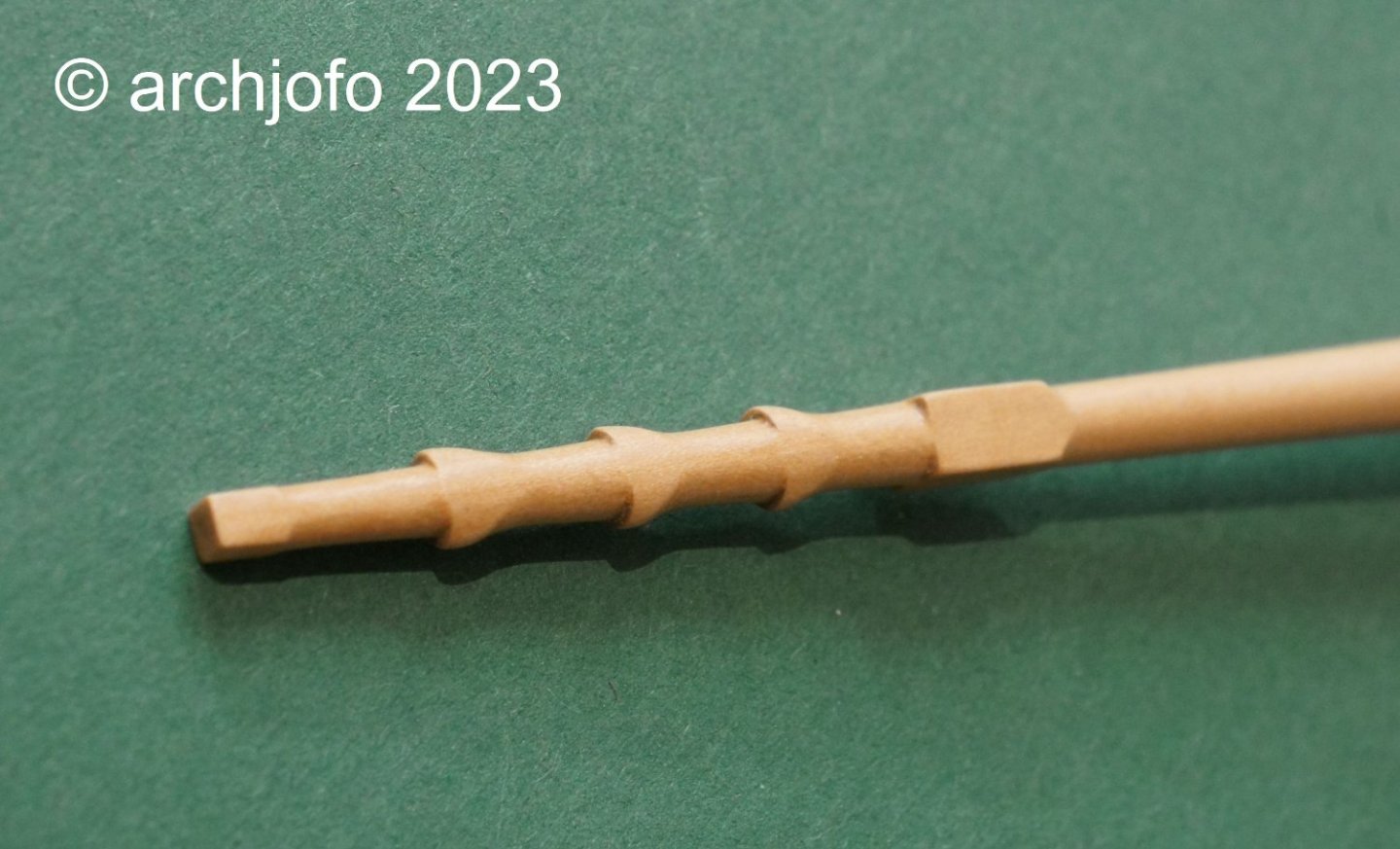
The next picture shows the finishing of the octagon in the center of the yard.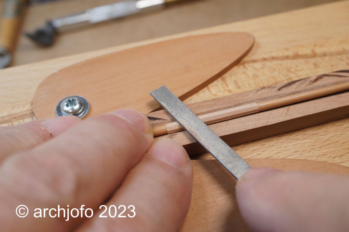
The last picture should give an impression of how filigree the topgallant yards are compared to the lower yards. It shows the yardarms of the main yard compared to the mizzen topgallant yard. The octagon of the yardarm of the mizzen topgallant yard still has a width of 1.3 mm at the outer end.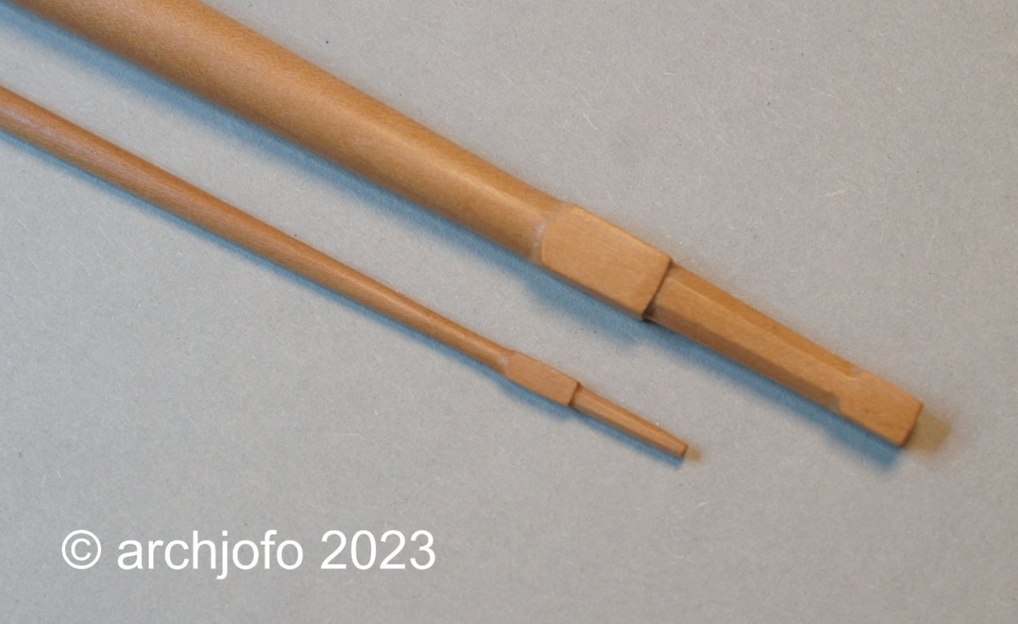
Of course, the royal yards can be made even thinner and more filigree. Especially the octagonal shaping at the yardarms requires special care.
To be continued ... -
Hello Siggi,
Thanks for the pictures.
It looks as if this is a lamp that is placed below the wind rose.Accordingly, Keith's ( @Keith Black ) reasoning would be absolutely correct.
- mtaylor, Keith Black and FriedClams
-
3
-
Maybe the compass question can still be solved,
in the meantime things will continue with the yards:
Continued: Making the yards - main topsail yard - Vergue de grand hunier
For long enough I evaded the decision to execute the yardarms of the main topsail yard. Further research on this did not bring any new findings.
Now that the holidays are over and with renewed vigor in the new year, I have decided on the following embodiment of the yardarms of the topsail yards, as already signaled in one of the last posts:
So now we can continue with the production of the yards.
Sequel follows …- scrubbyj427, mbp521, Keith Black and 15 others
-
18
-
Hello Keith,
this question is quite justified, and of course I have already asked myself. So I looked for examples where a lamp is attached to the bottom of the case. Like Bob, I reasoned that this is how the light shines from below between the hanger and the compass card.
But like I said before, I couldn't find anything about it.
In the end I don't know.- FriedClams, Keith Black, mbp521 and 2 others
-
5
-
-
Hello fellow colleagues,
Thank you for your interesting contributions. Andy's explanation
(@realworkingsailor) meanwhile I also think it's very plausible. Thank you for this post too.- Keith Black, FriedClams, mtaylor and 1 other
-
4
-
14 hours ago, bdgiantman2 said:
It almost seems to me to some kind of small external gear to the compass box. Was going to guess a part of the tiller operation but then I realized that La Creole would have still have rope tiller around the wheel and into the hull. But as the picture of the contemporary model shows, maybe it is a broken off arm for like the ship's bell.
It's an interesting approach, let's see.
22 hours ago, Keith Black said:Johann, I believe it to be a lamp.
Isn't it too far down for a lamp?
- FriedClams, Keith Black and mtaylor
-
3
-
Hello fellow colleagues,
happy new year 2023,
and above all health.Before we continue with the yards with fresh energy and motivation, I would like to clarify one more question about the ship's compass.
ship compass
There is a cylindrical part on the back of the La Créole compass housing, which I recently discovered in one of the high-resolution images from the Musée national de Marine Paris.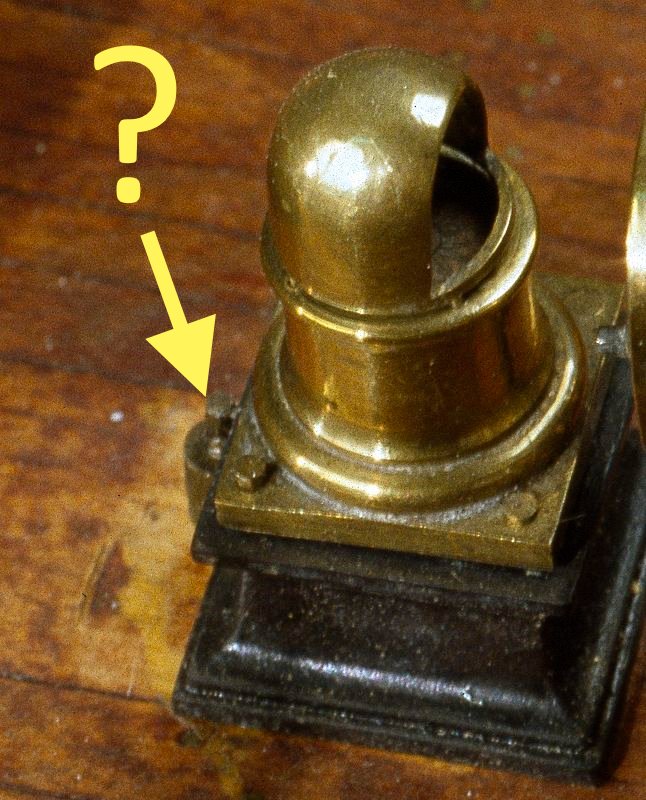
Source: Musée national de Marine Paris
This part can be seen even better on a photograph of the steering gear of a contemporary model from the Paris Museum (compass is unfortunately missing).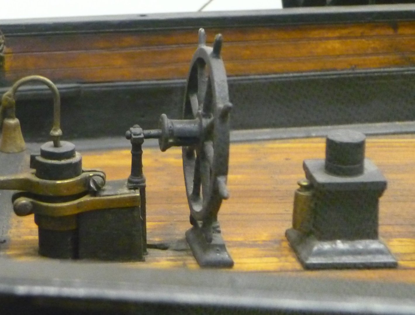
Source: Musée national de Marine Paris
I would like to add this part to my model and find out more about its function.
Based on what I've learned so far, I see two possibilities:
- It could be a so-called flinders bar (soft iron corrector), which reduces the influence of the compass needle on iron parts;
- or to a lighting.
However, the fact that it is a wooden ship speaks against the flinders bar. Only the guns could have a corresponding impact on the compass needle.
Basically, these brass binnacles of the compasses were illuminated with oil lamps, which were also cylindrical and designed with a round attachment (ventilation). From what I saw on the internet, for example, these cylindrical parts were located directly on top of the housing and were usually attached on both sides.
Therefore, I see this part in its function as a soft iron corrector, or is there another explanation?I would be very grateful for your help with this. It would be nice if I could get more information on this.
- GrandpaPhil, tlevine, ccoyle and 8 others
-
11
-
-
-
Continuation: Clarification of the yardarms
As already announced, I have now also drawn a variant with vertical cleats. However, with this variant I see a big problem with the guidance of the topgallant sheets.
In addition, I find on the contemporary ship models actually predominantly horizontally arranged cleats.The pictures of the La Créole, which were kindly given to me by the Musée national de Marine Paris, do not show the decisive details of these filigree parts in spite of a higher resolution. But in connection with the already shown yardarm of the Le Suffren I will most likely realize the previously drawn variant. The yardarm of the Le Friedland 1810 also goes in this same direction.
During all the research I also found out that the yardarms of the lower yards so far are not quite correct, so I simply made these yards (shown in the picture above) again, as shown below:
To be continued ...- GrandpaPhil, G. Delacroix, JOUFF and 21 others
-
24
-


La Créole 1827 by archjofo - Scale 1/48 - French corvette
in - Build logs for subjects built 1801 - 1850
Posted
@jdbondy
Hello,
very interesting and beautiful models. Thanks for the pictures.