

archjofo
-
Posts
1,398 -
Joined
-
Last visited
Content Type
Profiles
Forums
Gallery
Events
Posts posted by archjofo
-
-
-
Standing rigging for jib and flying jib boom - Bâton de foc et bâton de clinfoc
To complete the standing rigging (fore topmast stay and fore topgallant stay) for my French corvette, it finally became necessary to attach the jib and outer jib boom. Since these are very delicate and therefore very sensitive parts of the model, I delayed their assembly as long as possible. One or the other ship modeler might have already made the painful experience that a small carelessness leads to the breakage of these booms.
Before the realization, extensive research was done on the required detail elements. The information in the monograph on La Créole by J. Boudriot is not sufficient for this. In addition, some points concerning the guidance of the rigging (mooring in the forecastle), the dolphin striker (angular position) and the flying jib boom (length and attachment) had to be clarified.
I tried to record the compiled results in my new sketchbook (the old one is already full), as can be seen below: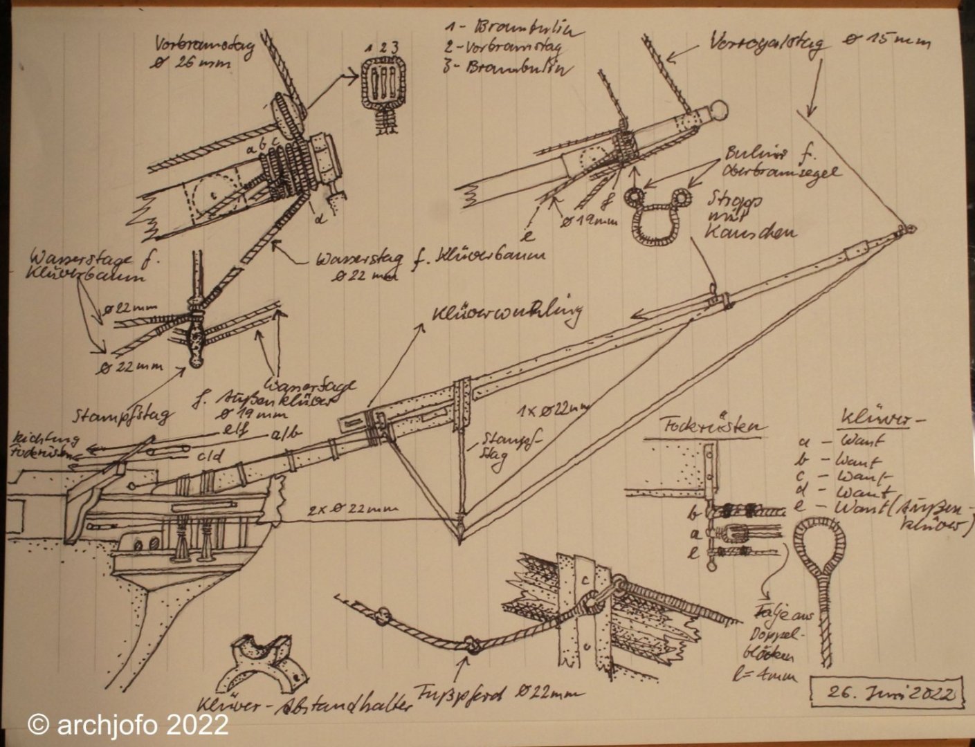
After more intensive occupation with this topic, I have only realized what a wealth of detail it contains. However, a few open questions still remain, such as whether foot ropes were also attached to the flying jib boom and whether they were single or double.
On the next picture you can already see some rigging elements with jib and flying jib boom. Besides the spacer and the triple block, the travelers are also shown. The so-called jib inhaulers are later guided over the single blocks attached to them. It should be mentioned that these are the smallest blocks of the model I have made so far, with a length of 2.8 mm.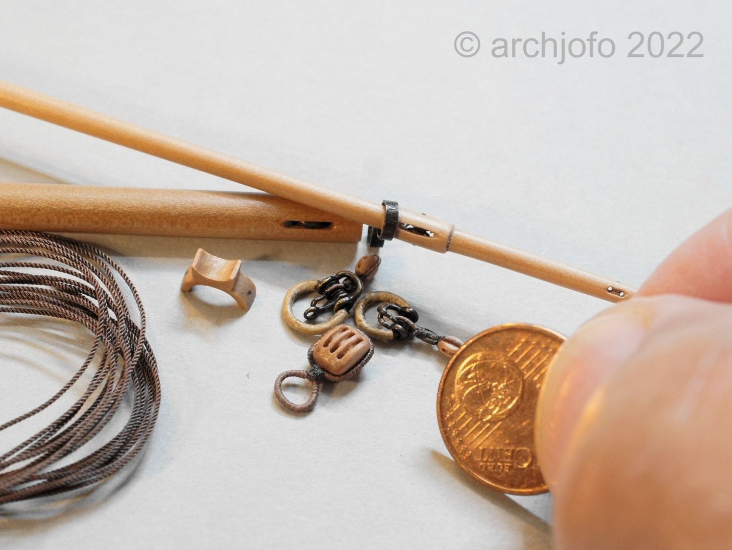
After making the necessary ropes, I will soon be able to start rigging the jib boom step by step, but more about that soon.
To be continued ...- Nunnehi (Don), GrandpaPhil, Gahm and 28 others
-
 26
26
-
 5
5
-
Thank you for the interest and the nice comments.
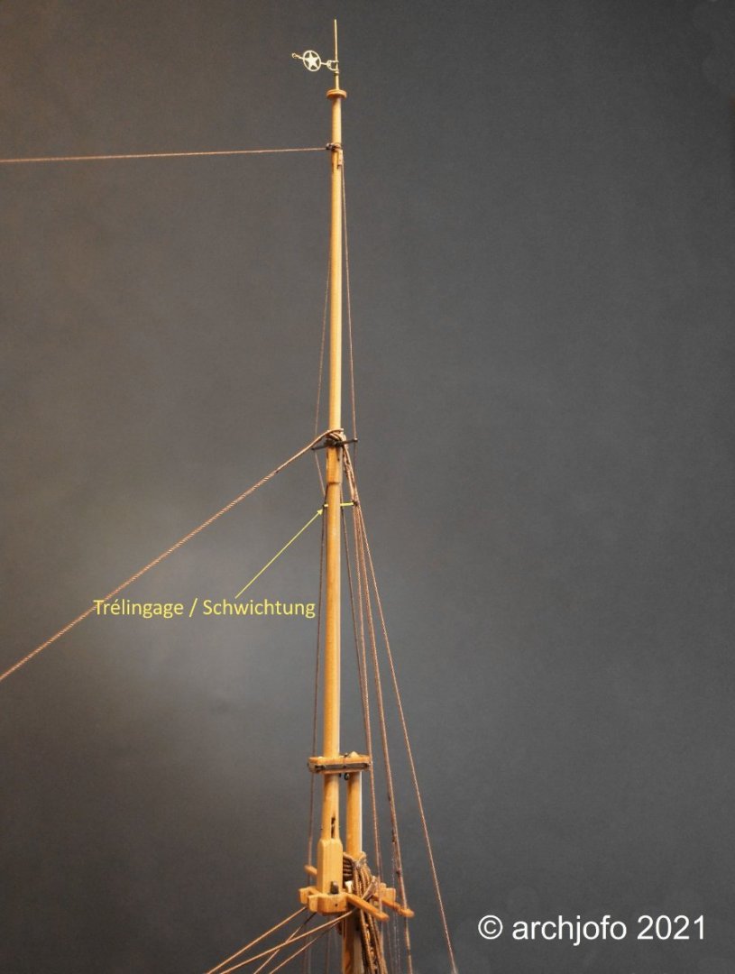
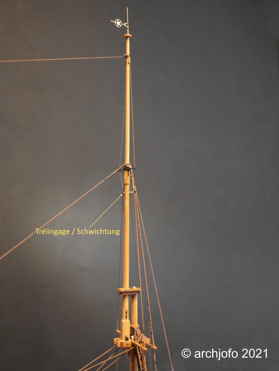
Also thanks to all for the many LIKES.Continuation: Catharpins - Trélingage
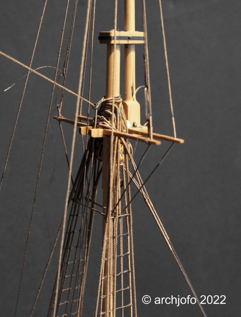
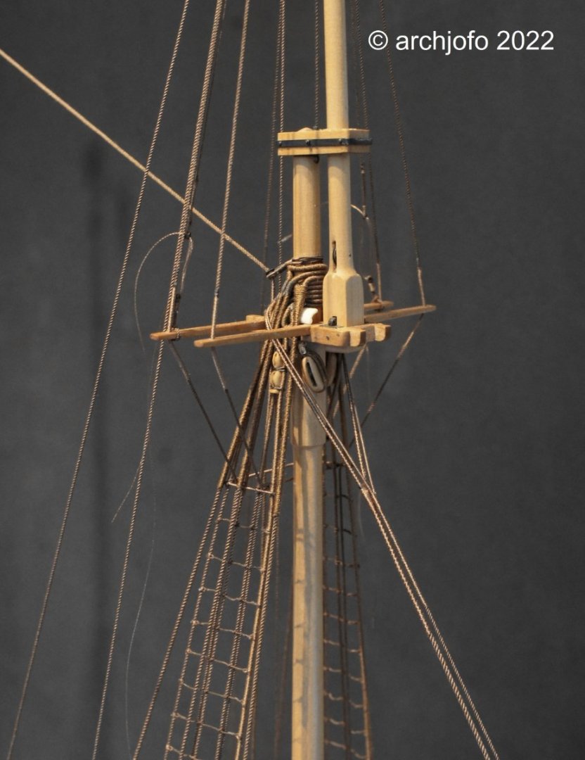
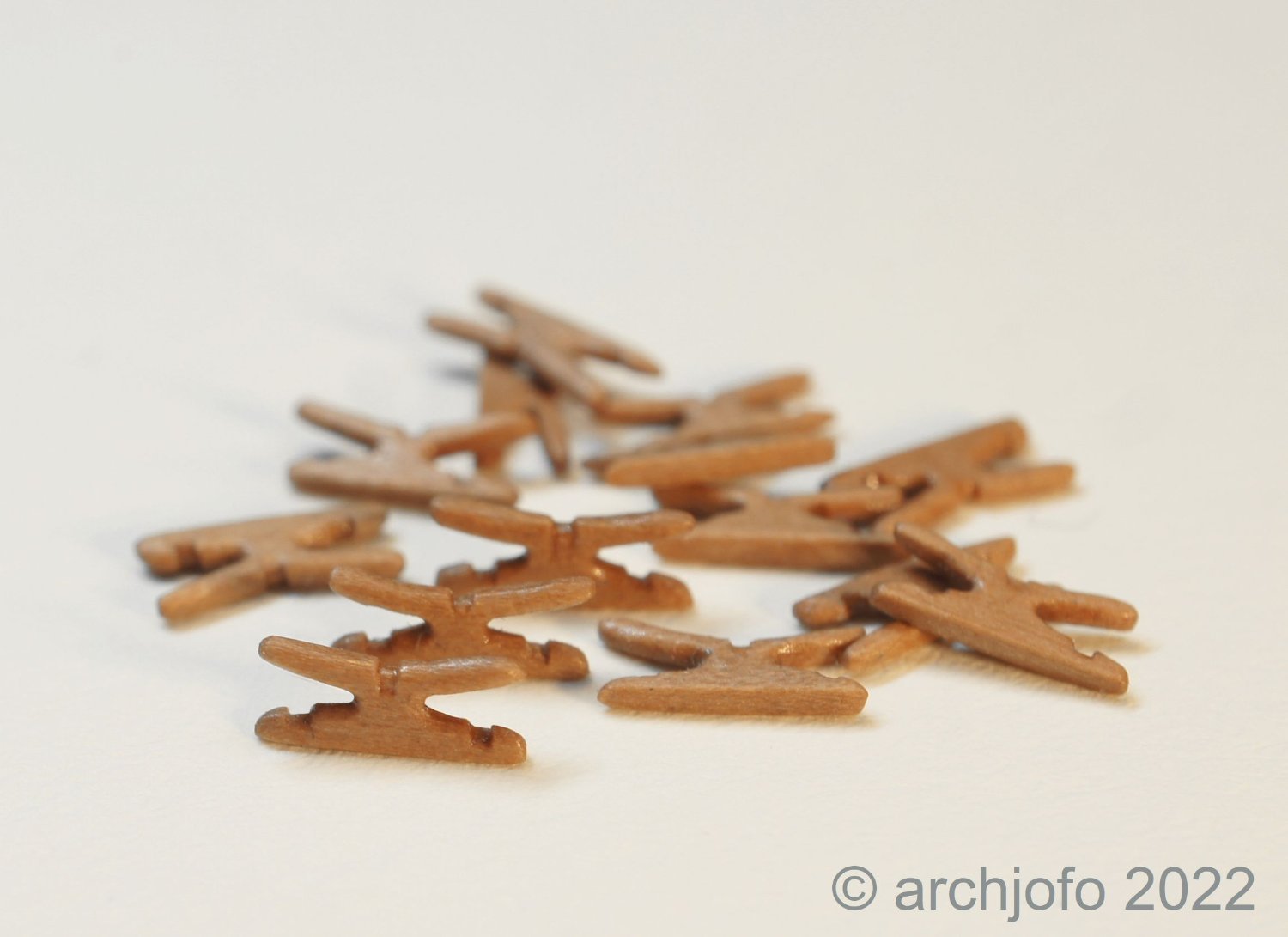
As already explained some time ago in my construction report LINK, the shrouds of the topmasts and topgallant masts of the La Créole were also equipped with catharpins.
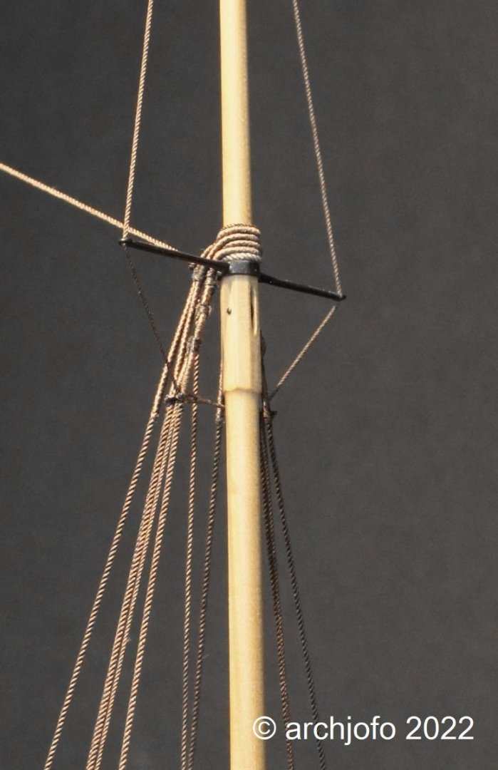
The following picture shows that the catharpin for the topallant shrouds is much smaller compared to the catharpin of the lower shrouds of the mainmast.
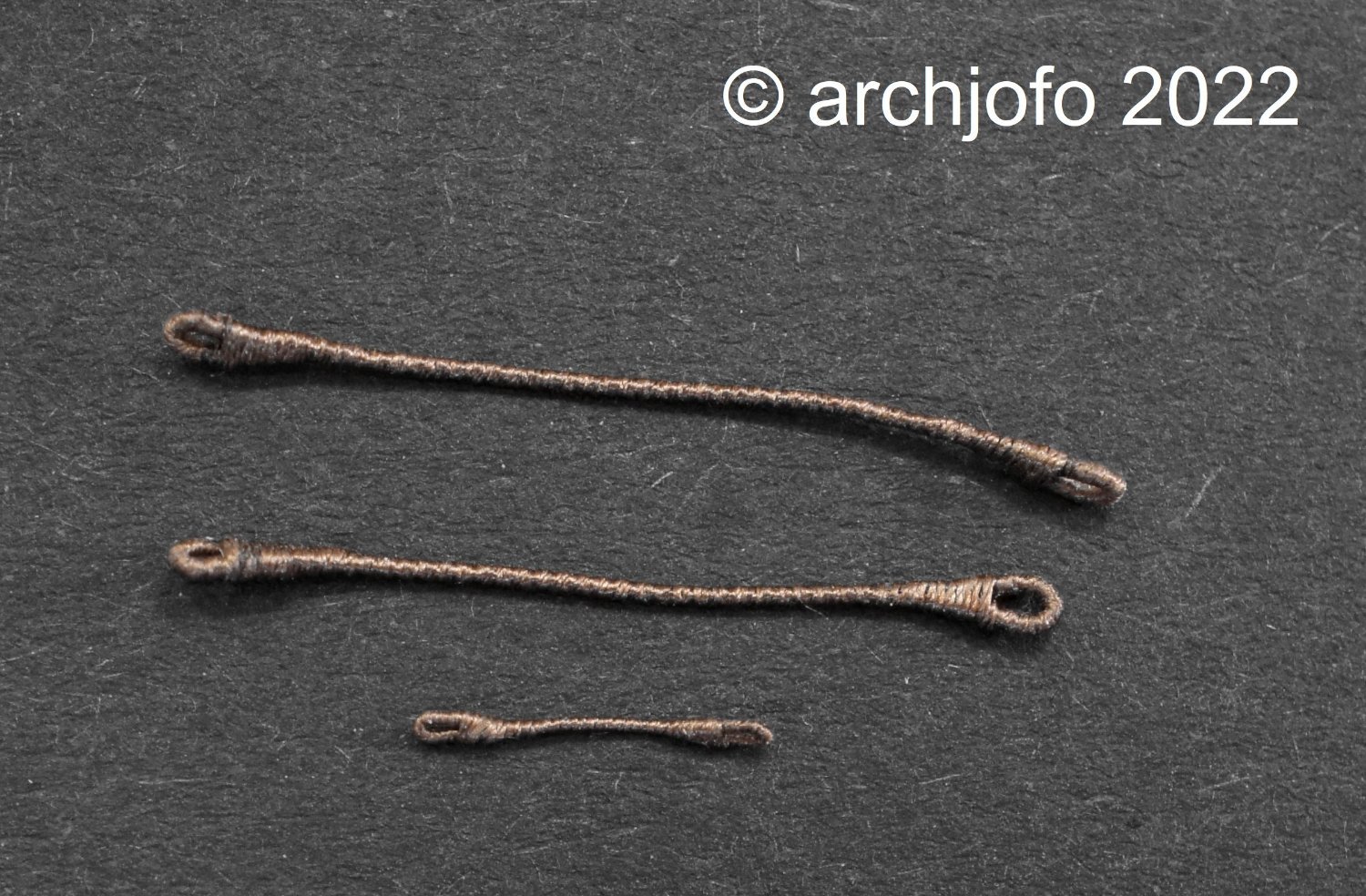
The next picture compares catharpin for the lower shrouds, the topmast shrouds and topgallant shrouds.
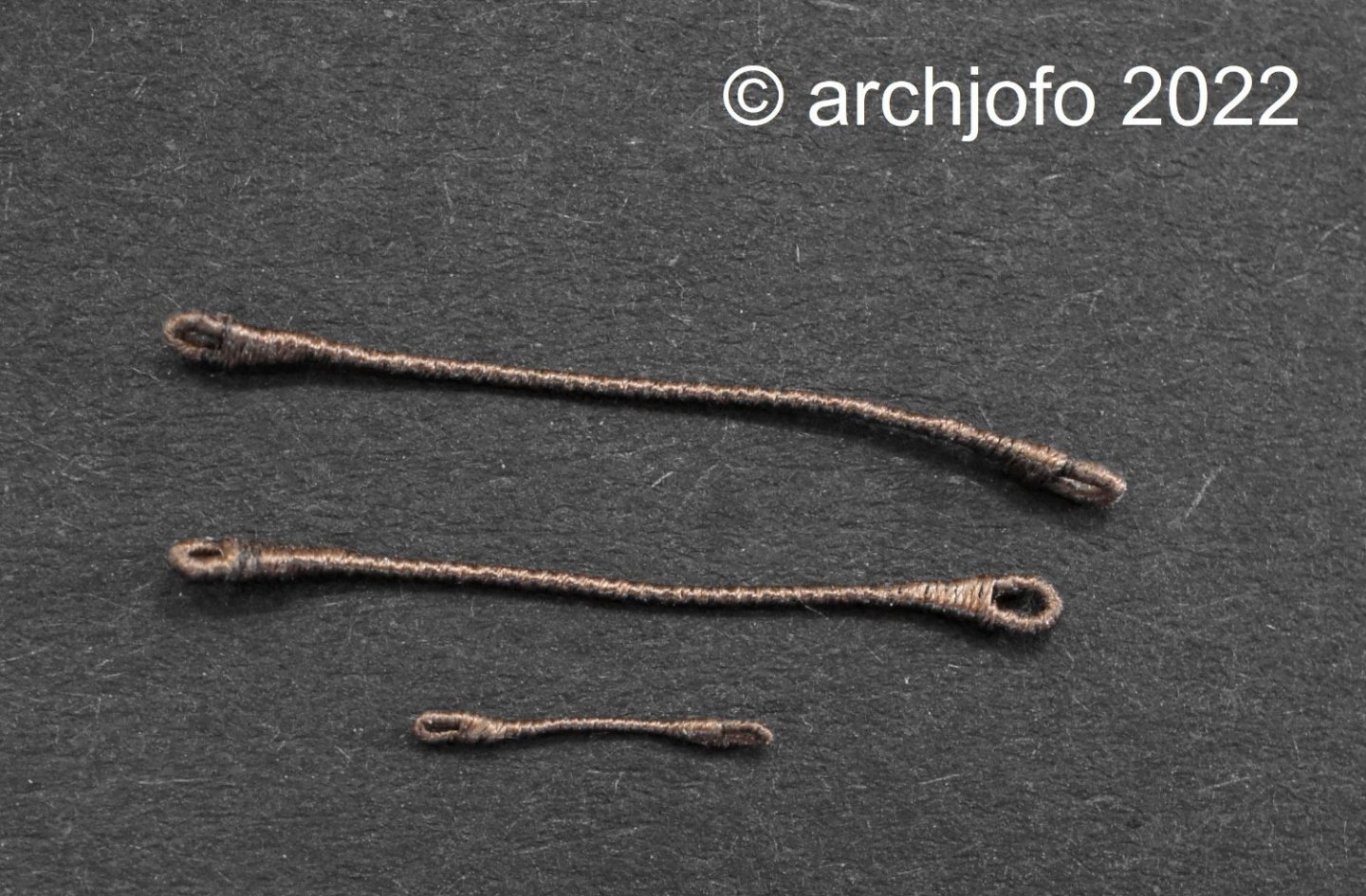
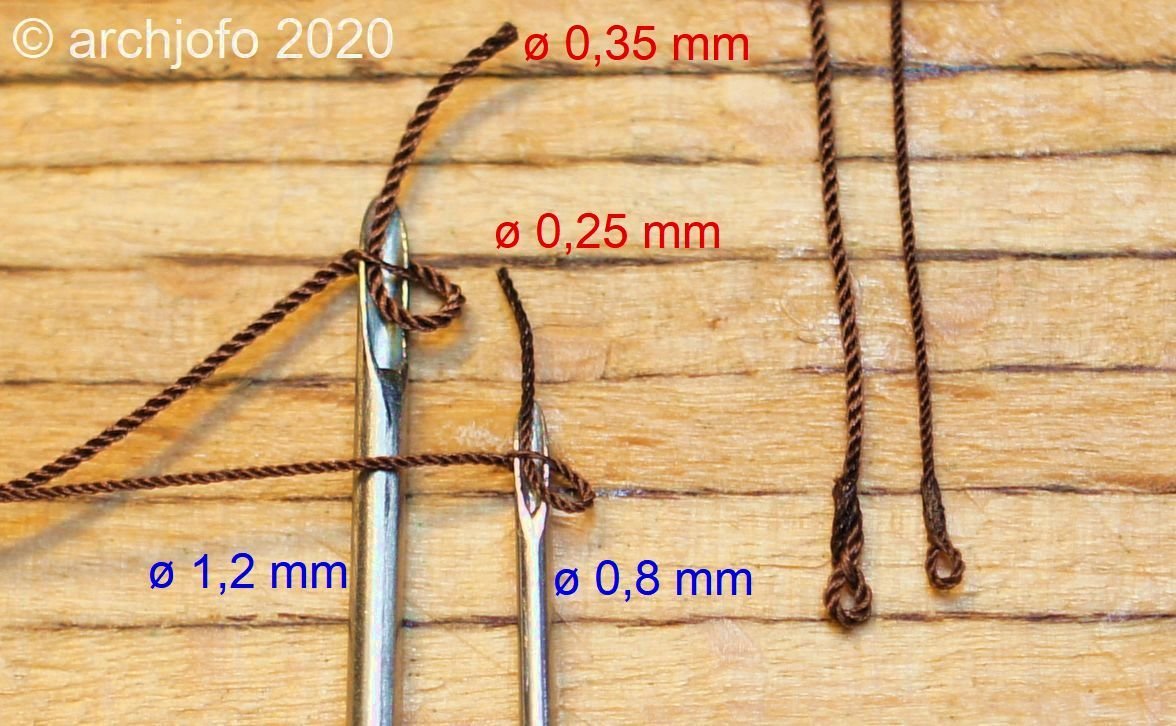
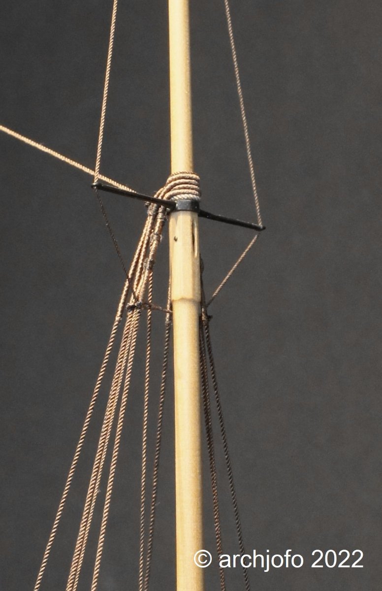
With a length of about 10 mm from a 0.25 mm served rope, the catharpin of the fore topgallant shrouds was then lashed in place.
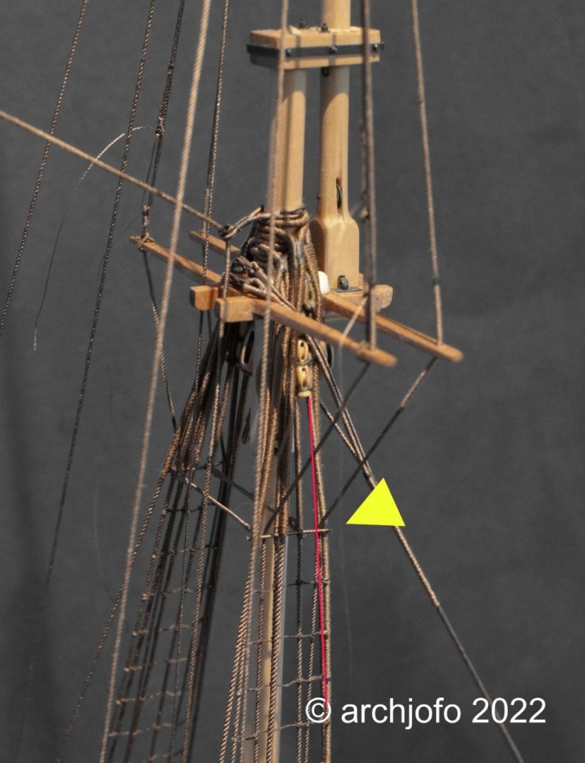
The last pictures show the already lashed catharpins (0.35 mm served ropes) of the topmast shrouds. The comparison shows what happens if the length of the catharpins is not made accurately. When the shrouds are tightened, they give way and move outward. Therefore new catharpins had to be made again.
To be continued ...- CiscoH, giampieroricci, Keith Black and 31 others
-
28
-
6
-
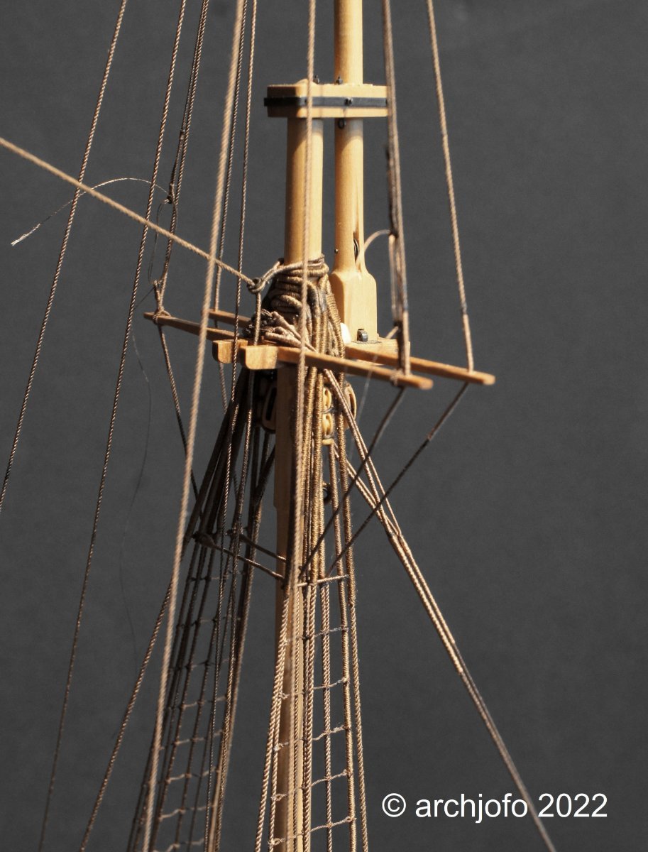
Continuation: Fixing the topgallant shrouds
In the meantime, all topgallant shrouds have been attached to the corresponding fittings of the deadeyes. The final fixing of the lashings only makes sense after all the shrouds have been installed.
The ropes were fastened with a simple splice.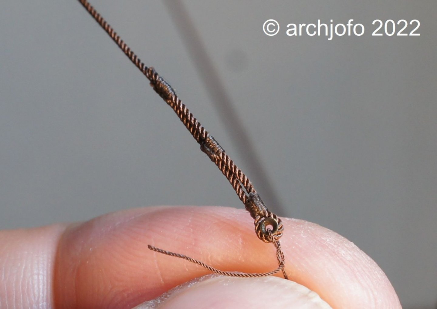
The lashings of the topgallant shrouds are here attached to the foremast behind the 2nd and 3rd top mast shroud.
Next I will make the catharpins of the top- and topgallant shrouds.
See you soon ... -
-
Fixing the topgallant shrouds
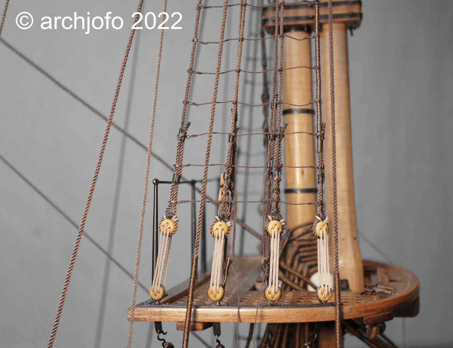
A long time ago I dealt with this topic in more detail, but without any concrete result. However, I can no longer postpone the implementation of this detail. According to my research and a corresponding interpretation of the description in the monograph of La Créole, the topgallant shrouds are now fixed by lashings, which are attached to the fittings of the deadeyes. The respective lashing is made with thimbles.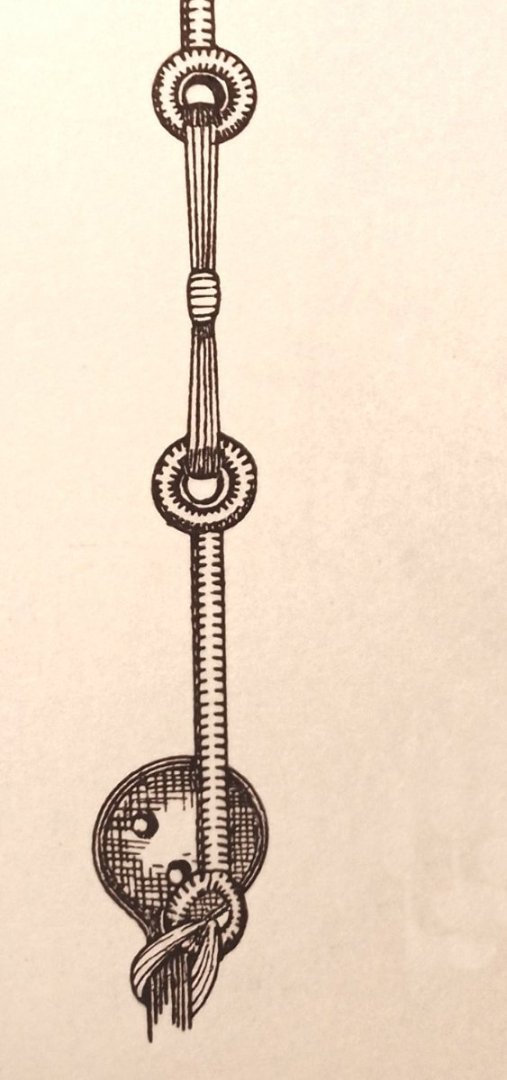
On the next picture I show the course of the topgallant shrouds using the main top as an example.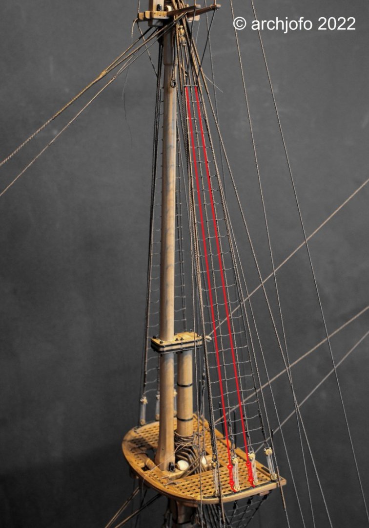
So once again thimbles had to be made, 24 of them in total. In relation to the deadeyes, the thimbles should not be too big, of course. That's why I had to introduce another thimble size (ø 0.9 mm / ø 1.2 mm / ø 2.0 / ø 2.5 mm) in addition to the ones used for this model so far. For this purpose I bought brass tubes with a diameter of 1.0 mm, which finally resulted in thimbles with a diameter of about 1.6 mm.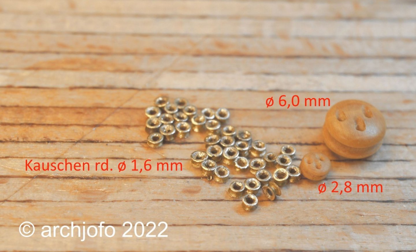
In the meantime I only make the thimbles with a suitable centre punch. With the cone-shaped point I form the tube section into a thimble with lightly dosed hammer strokes, as shown in the following picture.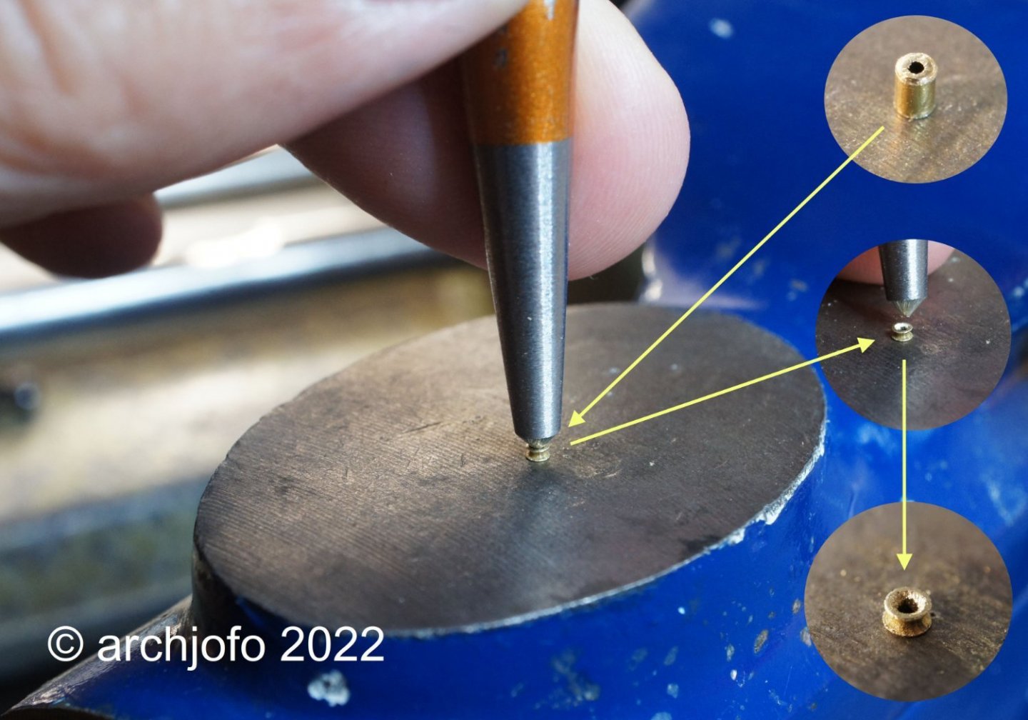
To make the strops for the lower thimbles I use served ropes with ø 0.35 mm. For tying to the fittings of the deadeyes, eyes are formed as shown in the drawing before.
The last picture shows the finished strops, 4 x 3 pieces in total. The shorter strops are for the mizzen mast.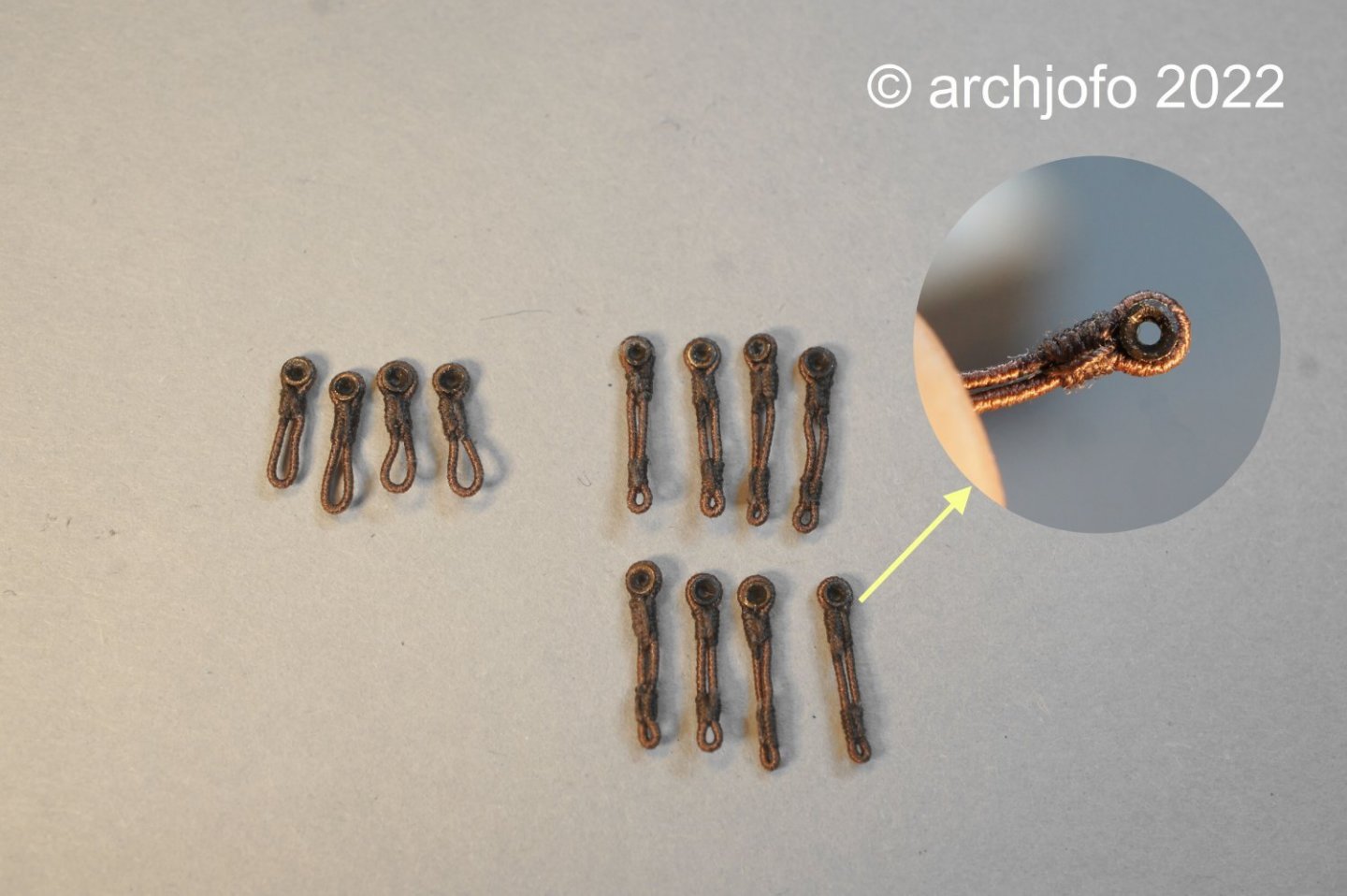
I will report about the fixing of the topgallant shrouds on the model soon.
To be continued ... -
-
-
Hello,
thank you for the nice compliments.
Of course I would also like to thank you all for the many LIKES.
Continuation: Cleats for the topgallant lifts and royal lifts
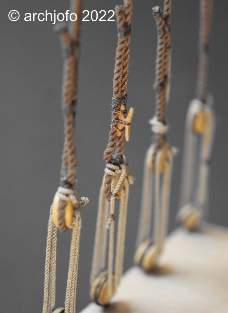
In the meantime, the cleats have been grooved for the central lashing and are ready to be tied down.

After temporarily securing the cleat to the topmast shroud, I begin the top and bottom tying. Then I rotate the cleat to its final position aft and complete the process with the center lashing.
The last picture shows the two cleats of the starboard side topmast shrouds of the foremast. This is where the lifts of the topgallant yard and royal yard will be attached later.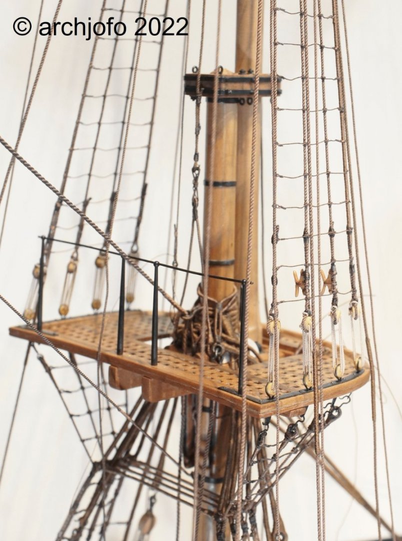
To be continued ...
-
-
-
Continuation: Cleats for the topgallant lifts and royal lifts
Since tying the cleats to the shrouds did not turn out to be as problematic as originally feared, I went a step further to approximate the original method of execution..jpg.7ac193fc3f30f0c2fba71e6e00d1f995.jpg)
Source: "Le gréement des navires anciens (1700-1850)", Gérard PiouffreThe following picture shows the result:
Accordingly, I will now attach the cleats for the lifts of the topgallant yards and royal yards to the topmast shrouds.
To be continued ...
-
Continuation: Cleats for topgallant lifts and royal lifts
Mostly it comes differently than one thinks!
So in this case. While I had thought that binding the filigree cleats to the topmast shrouds would be very difficult, my first attempt showed that it would be relatively easy.
Before I started with the shrouds for this model, I first built a corresponding jig for experimental purposes. This served later among other things also with decisions for attaching the ratlines. And now it served to test how best to attach the cleats to the shrouds.
The trick, if you can call it that at all, is to tie the cleats comfortably to the shrouds from the front, and then simply turn them backwards to the desired position.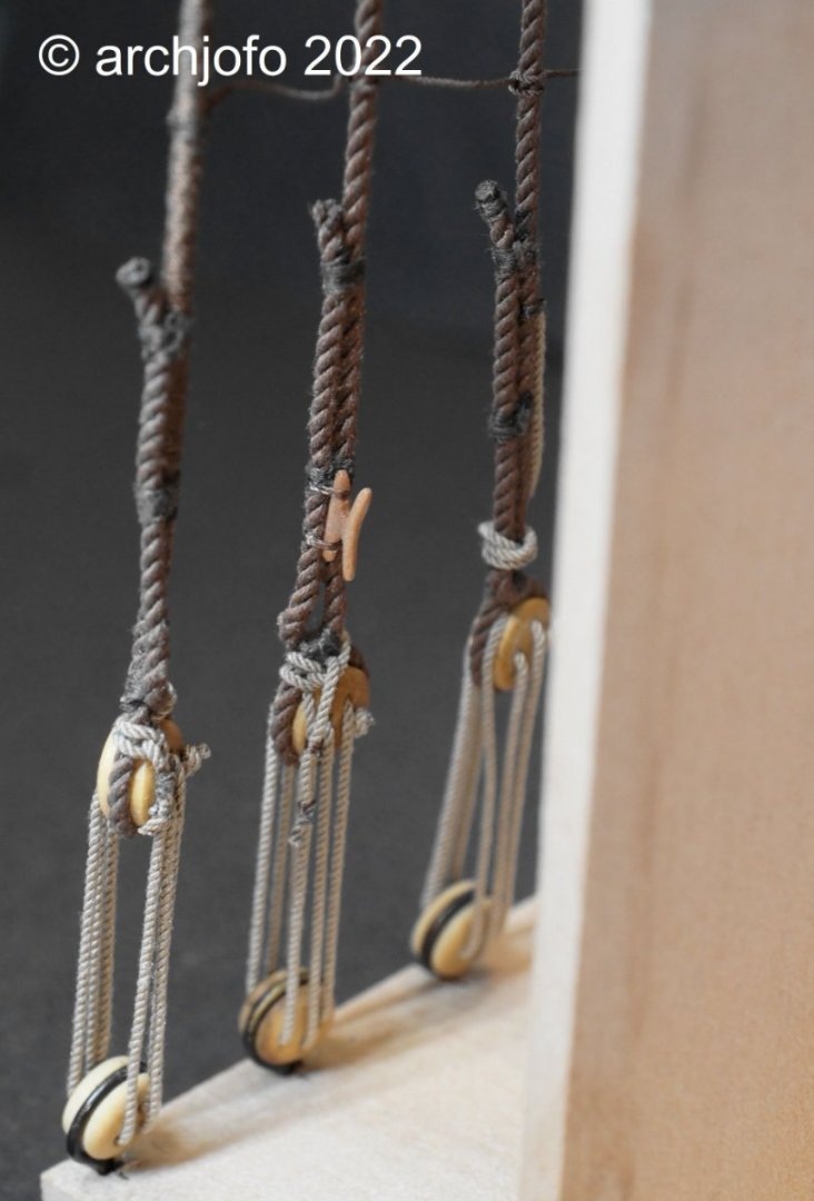
To be continued ...
-
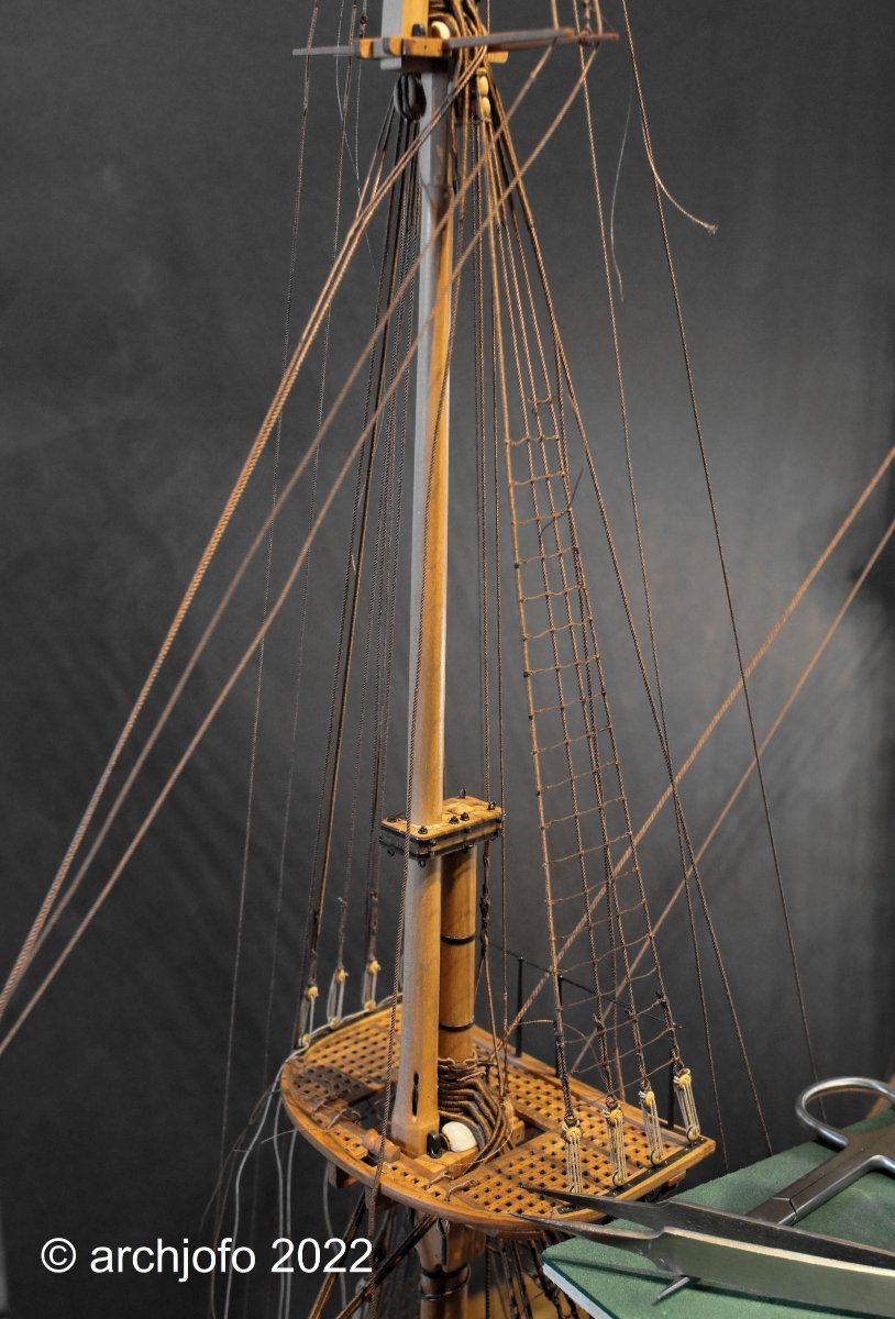
Cleats for the topgallant lifts and royal lifts
I almost forgot!
Wasn't there something else with the shrouds? There are a few details I'd better mention now.
The description of the monograph for La Créole itself does not clearly state how the lifts for the topgallant yards and royal yards are to be attached. As far as I could tell from the description, the lifts were attached somewhere in the area of the top. On the original photos of the Paris model of the La Créole, you can clearly see two cleats on each of the topmast shrouds. Until now, I could not clearly identify the ropes used there. However, after some research, my suspicions were confirmed. These are the lifts for the topgallant yards and royal yards.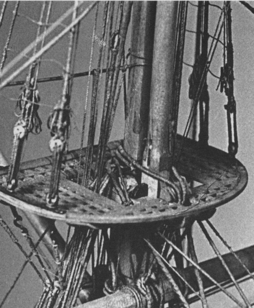
Source: Monograph by J. Boudriot, detail of original model
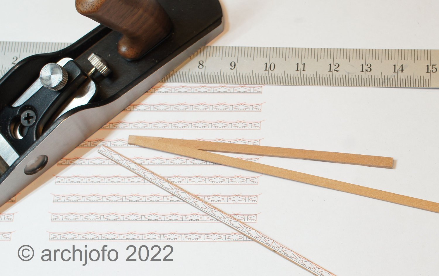
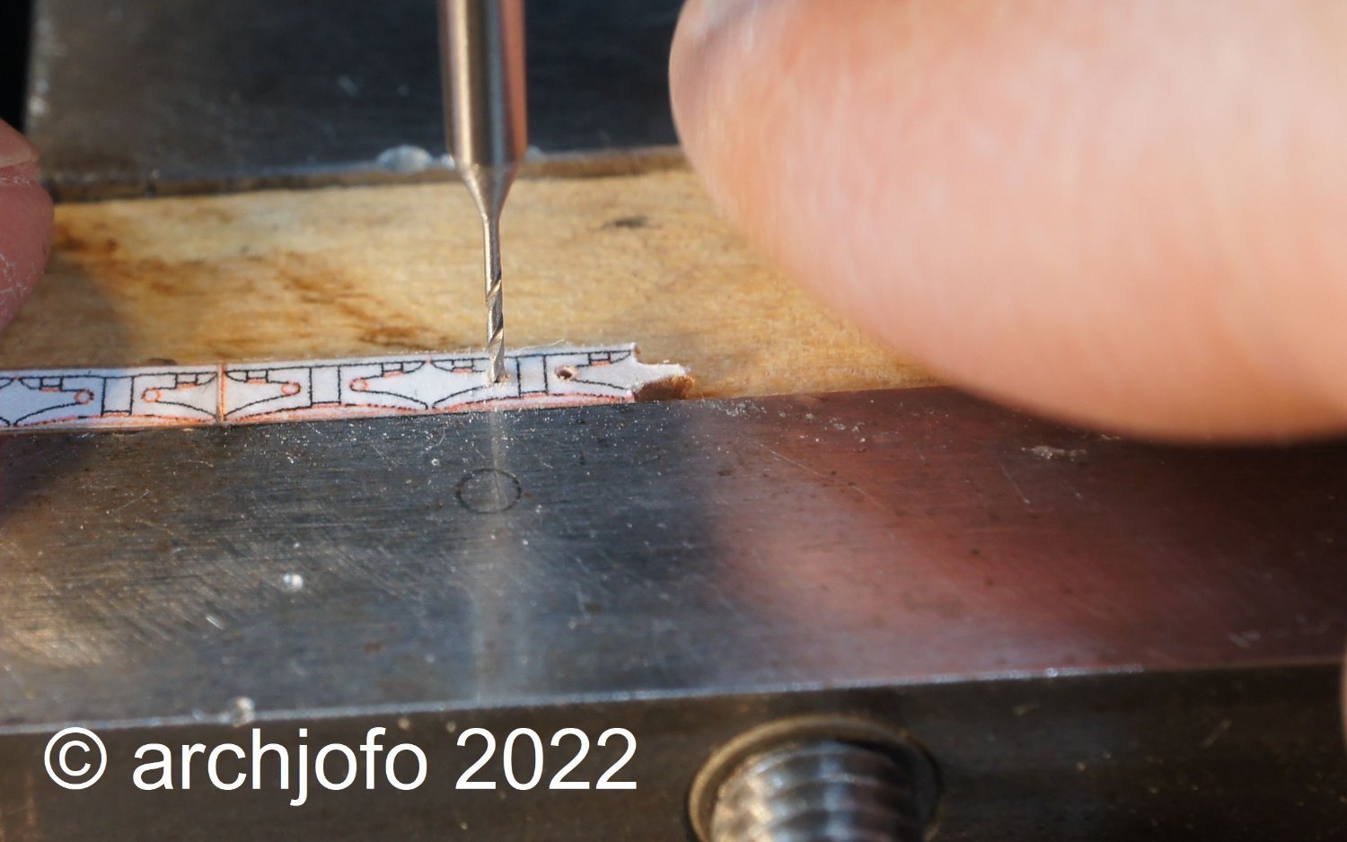
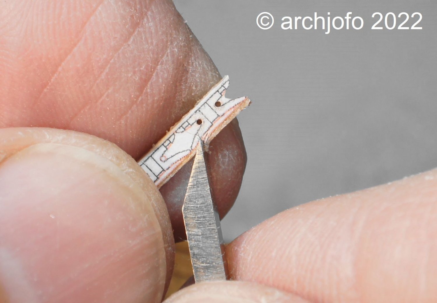
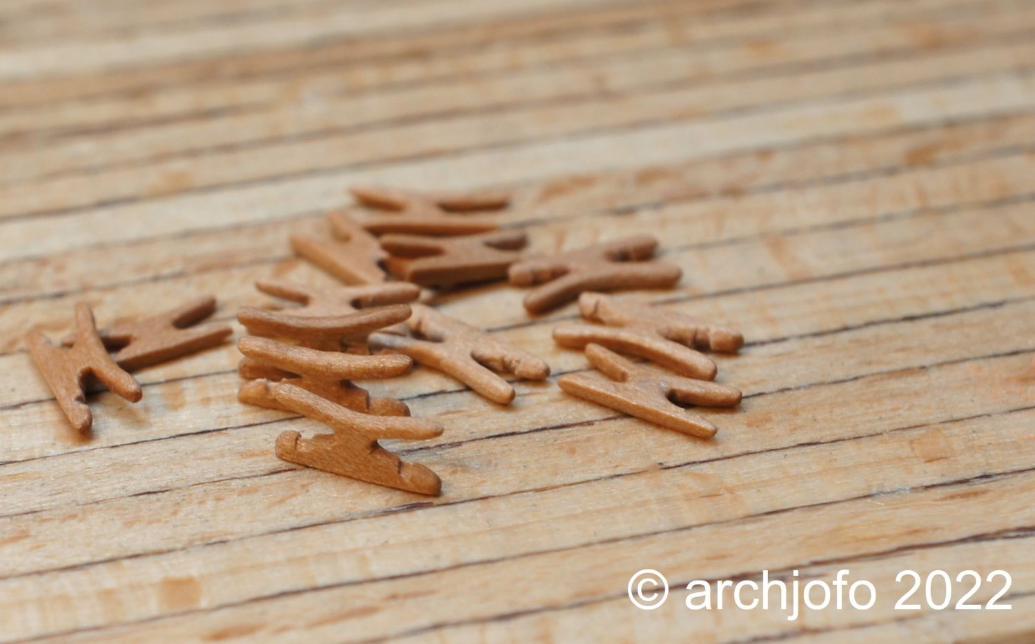
The next step was to clarify the shape and size of these cleats, a total of 3 x 4 pieces, which I derived from the original photograph and drew.
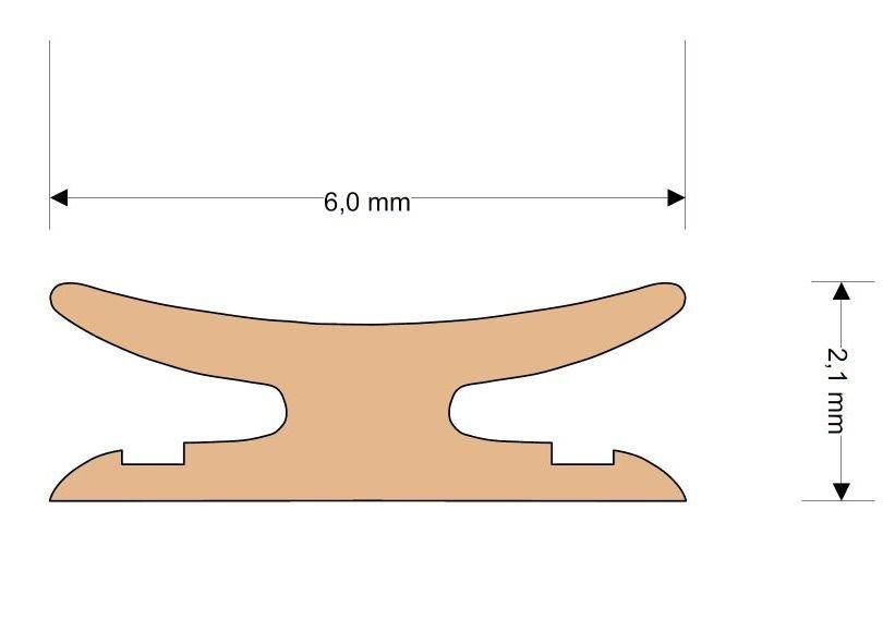
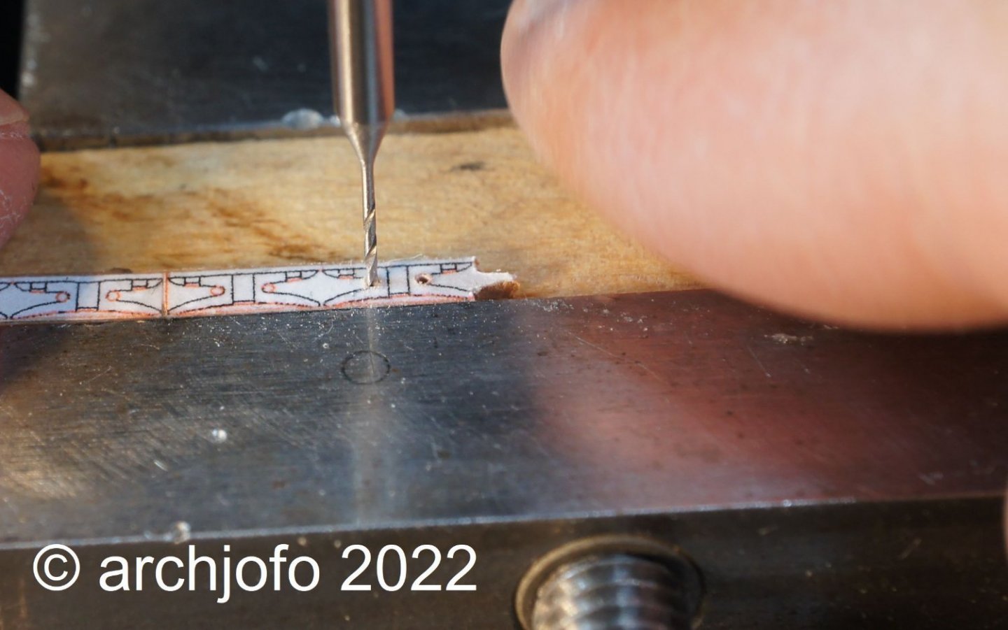
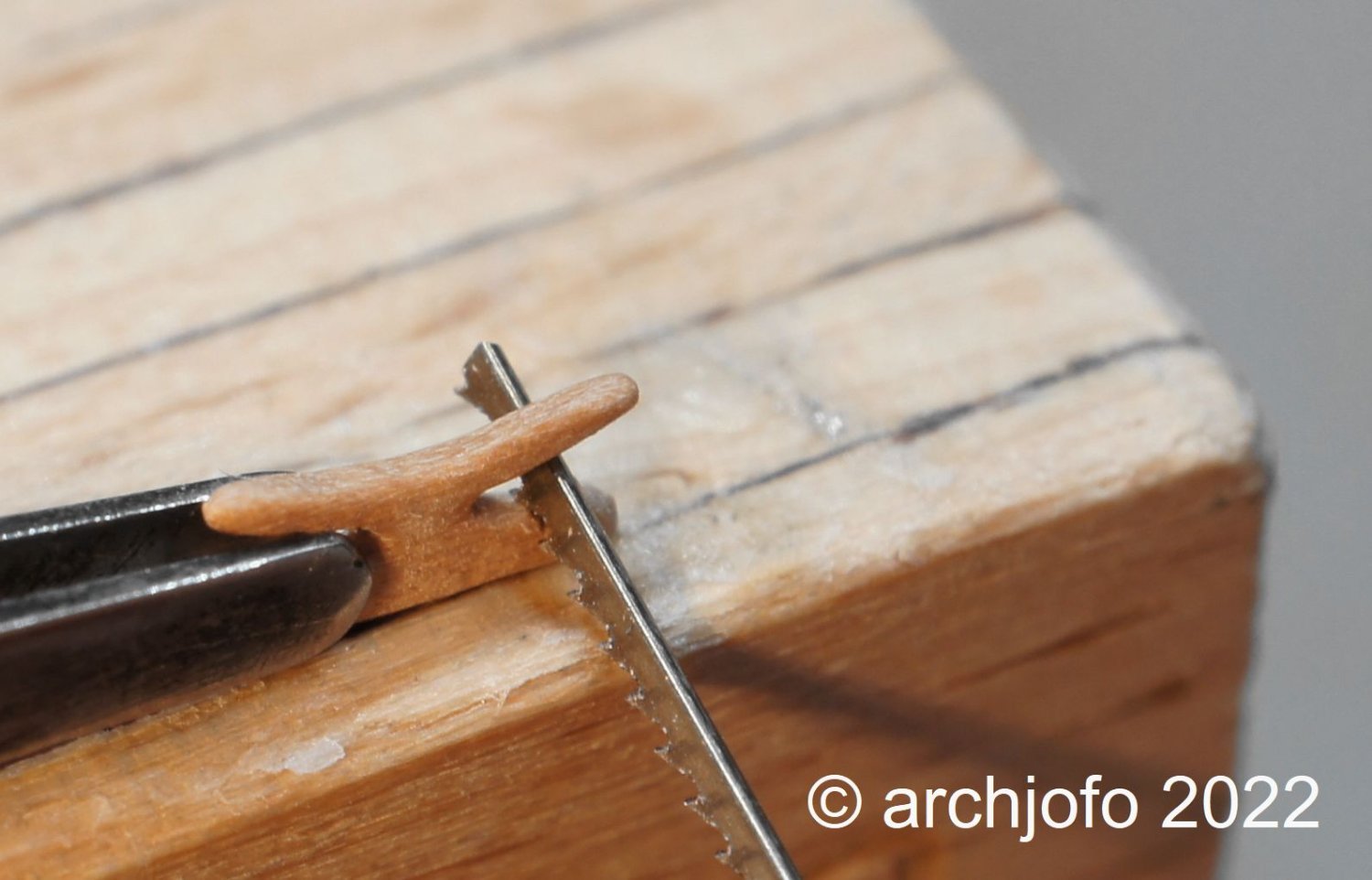
I made the cleats from service tree. The following pictures show different stages of the production.


The last picture shows the result.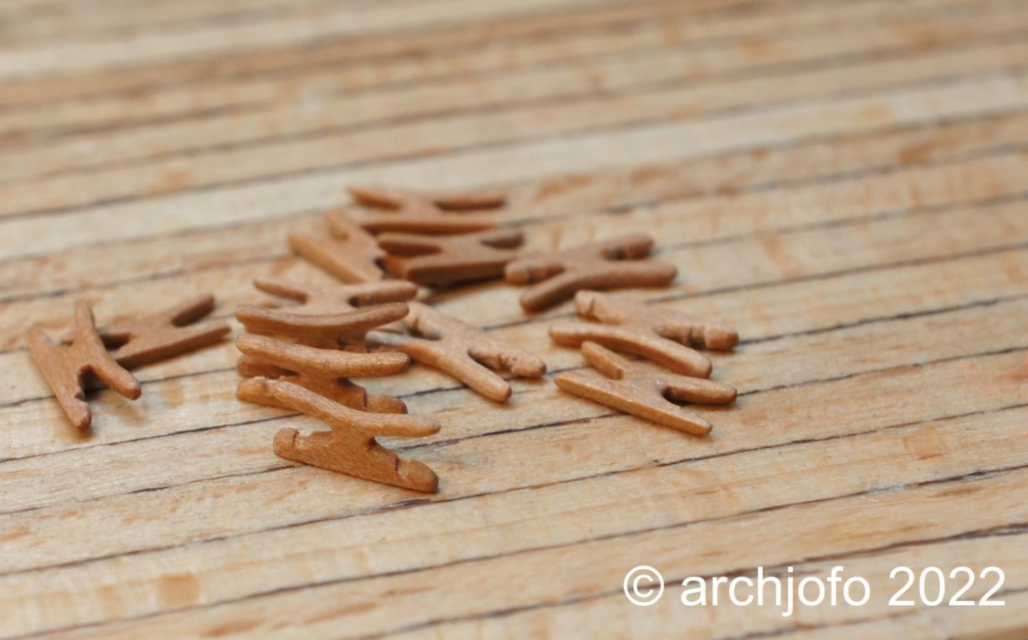
Attaching these cleats to the topmast shrouds will probably be another small challenge to master. -
Completition: Ratlines for the topmast shrouds - Enfléchures
It has been quite a while since I started attaching the ratlines for my French corvette at the lower shrouds.
Today I was able to tie the last ratline knots at the starboard side of the topmast shrouds and with the last binding the chapter -ratlines- was finished.
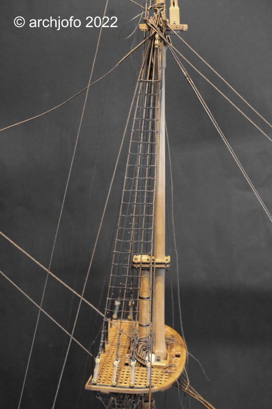
Before I start to make the yards, I still have some rest work to do for the standing rigging, e.g.
- Fixing the topgallant shrouds
- Catharpins for the topmast and topgallant shrouds
- Fore topmast- and fore topgallant stayTo be continued ...
- dvm27, SIDEWAYS SAM, Keith Black and 33 others
-
32
-
4
-
Hello,
thanks to everyone else for your interest.What is the saying?
Little by little the bird builds its nest ...😁
So it goes on here with small steps ... ratline for ratline ...Continuation: ratlines for the topmast shrouds - Enfléchures
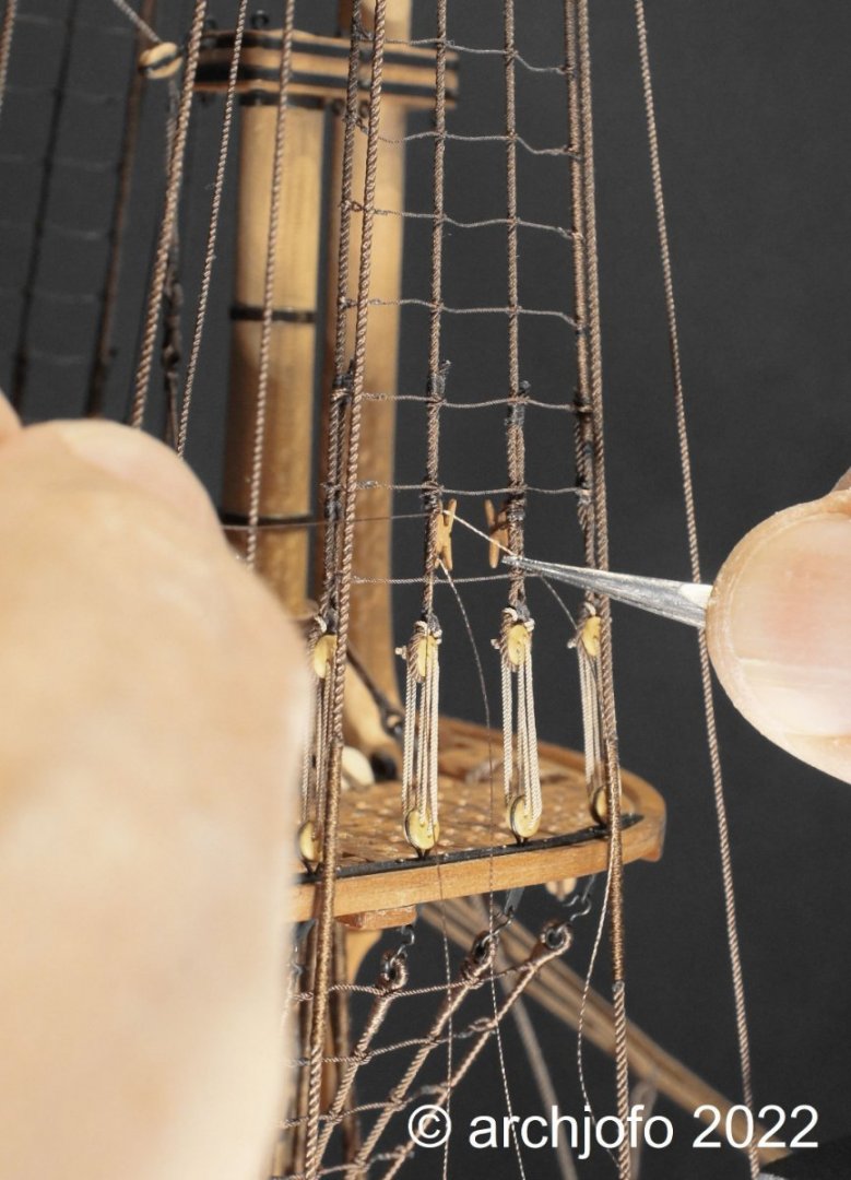
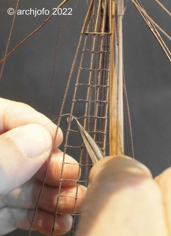
The last stage for the installation of the ratlines (ø 0.25 mm) was initiated, namely with the final fixing of the lanyards of the starboard side topmast shrouds.
On the following picture I have marked the corresponding place with an arrow, where work is going on at the moment.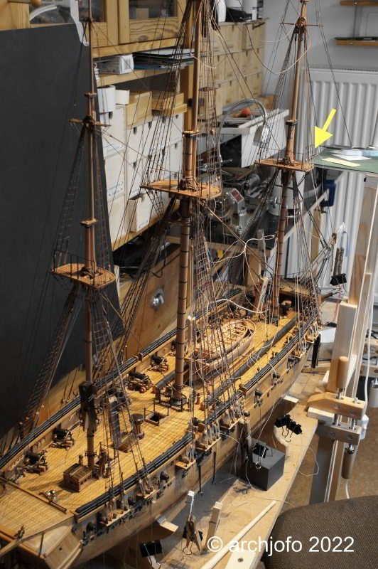
The next picture shows the fixing of a taljereep with the tweezers.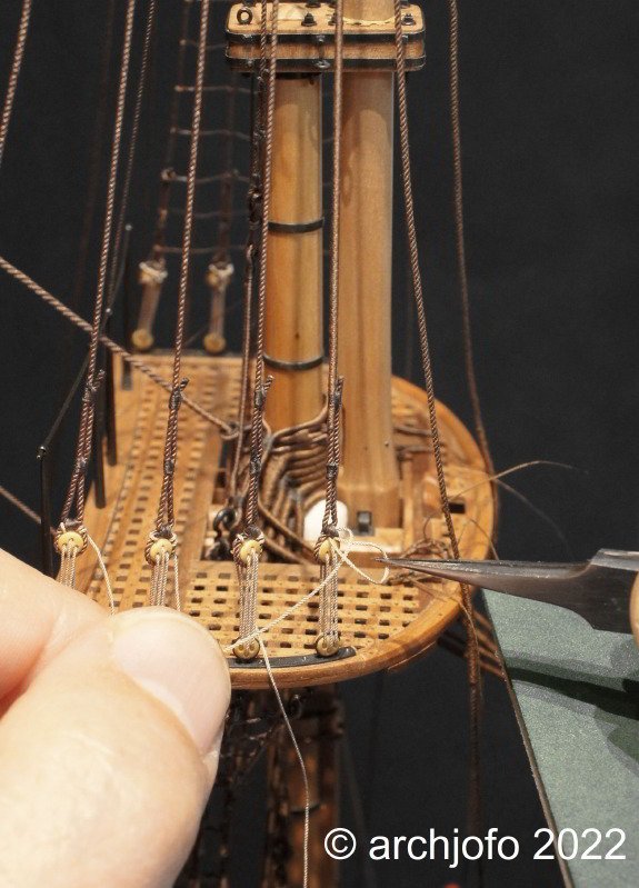
After fixing the lanyards of the topmast shrouds, the knotting of the ratlines can be started in the way already described several times.
To be continued ... -
That is simply an outstanding performance.
Master class !- albert and Seventynet
-
2
-
-
Hello,
Thank you for the positive reaction to my post.
Thanks also to all the others for the LIKES.Hello Thoma,
the best way to answer your question is to show you this picture.
I hope that I have answered your question in an understandable way.
-
Hello,
thanks for your nice comments, and all the others for the many LIKES.
Continuation: Ratlines for the fore topmast shrouds - Enfléchures
In the meantime, I have started working on the port side ratlines (ø 0.25 mm) of the fore topmast shrouds. These are already about three quarters made, as can be seen in the following pictures.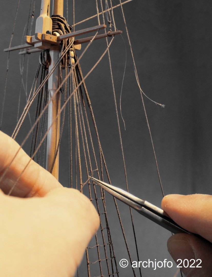
On the last picture I show again how the simplified splice for binding the ratlines to the outer shrouds is made step by step. For lifting and inserting the end of the rope twice between the strands, I use an appropriately prepared cannula, as already reported and shown.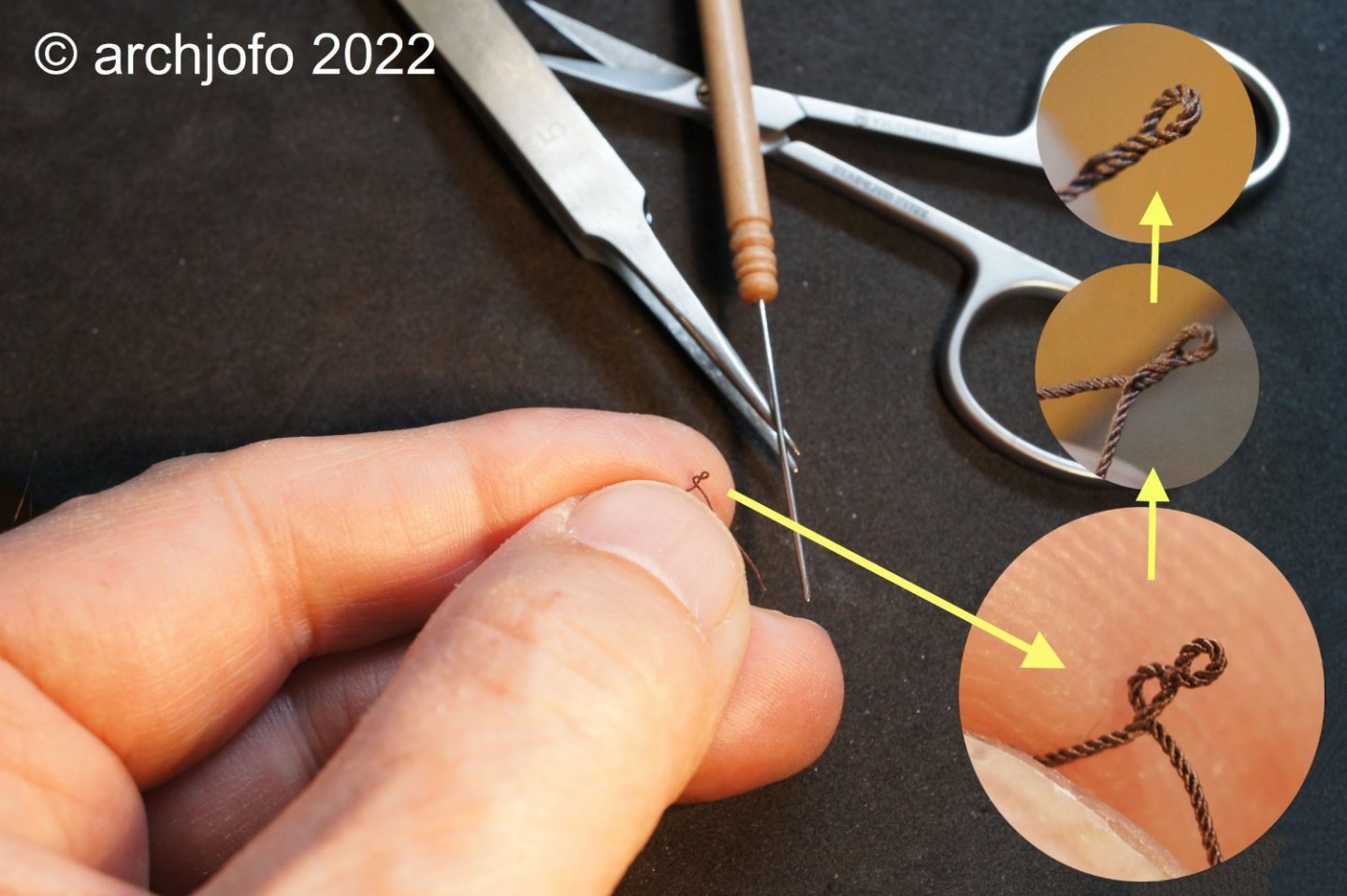
The end of the chapter -ratlines- is within reach.
To be continued ...- FriedClams, Nunnehi (Don), WalrusGuy and 31 others
-
32
-
2
-
Thank you very much,
also for the interest in my work,especially since I can't deliver anything new.I have already started with the ratlines of the topmast shrouds. In this respect, I already see a silver lining on the horizon ... 😁
The hand has healed well so far. However, due to the long immobilization with splint the fingers are a bit rusty. But it is getting better from day to day.
- tlevine, Jack12477, Keith Black and 5 others
-
8
-
Hi,
thank you very much for the good wishes.
Hello colleagues,
after a short creative break ... 😁... we continue here again:
Continuation: Ratlines for the topmast shrouds - Enflechures
With the addition of the ratlines for the topmast shrouds, it was necessary to clarify how the futtock staves are to be made here. In contrast to the more massive futtock staves of the lower shrouds, made of served brass rods, I used a rope with ø 0.35 mm for the topmast shrouds, which was soaked with super glue before serving.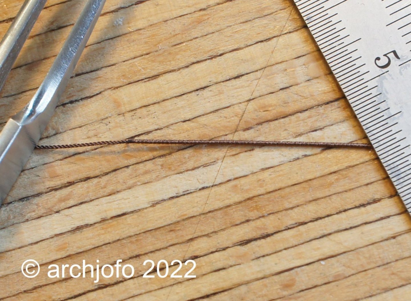
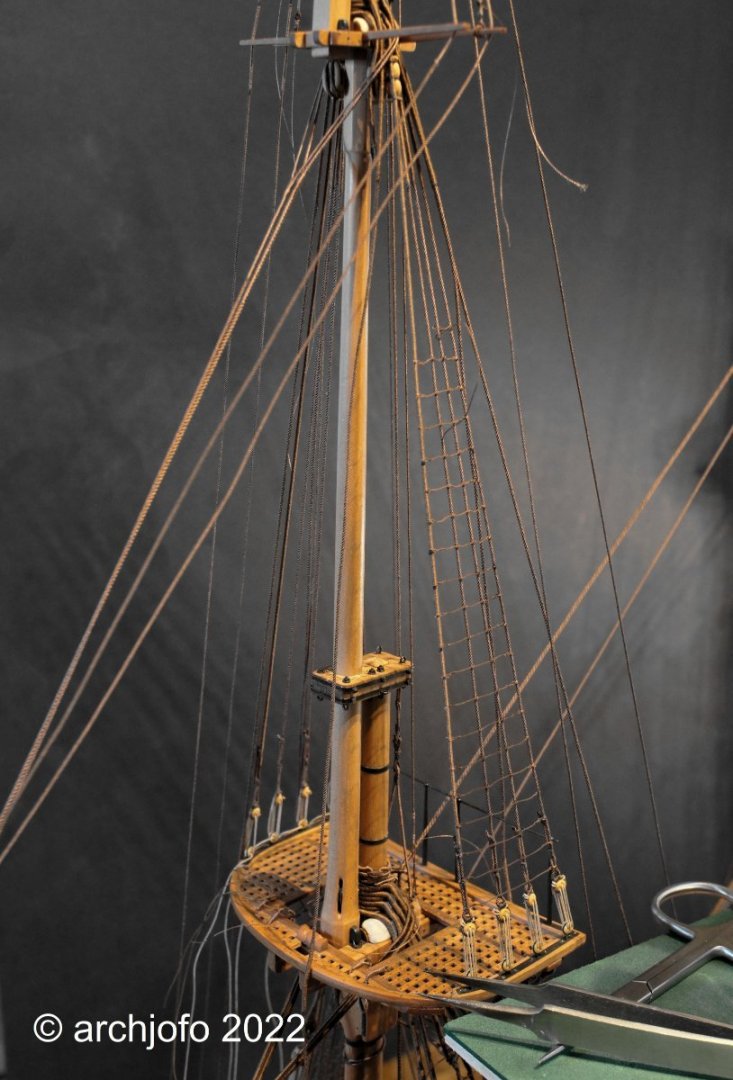
After fixing the futtock stave, I could attach the last ratlines of the port side main topmast shrouds.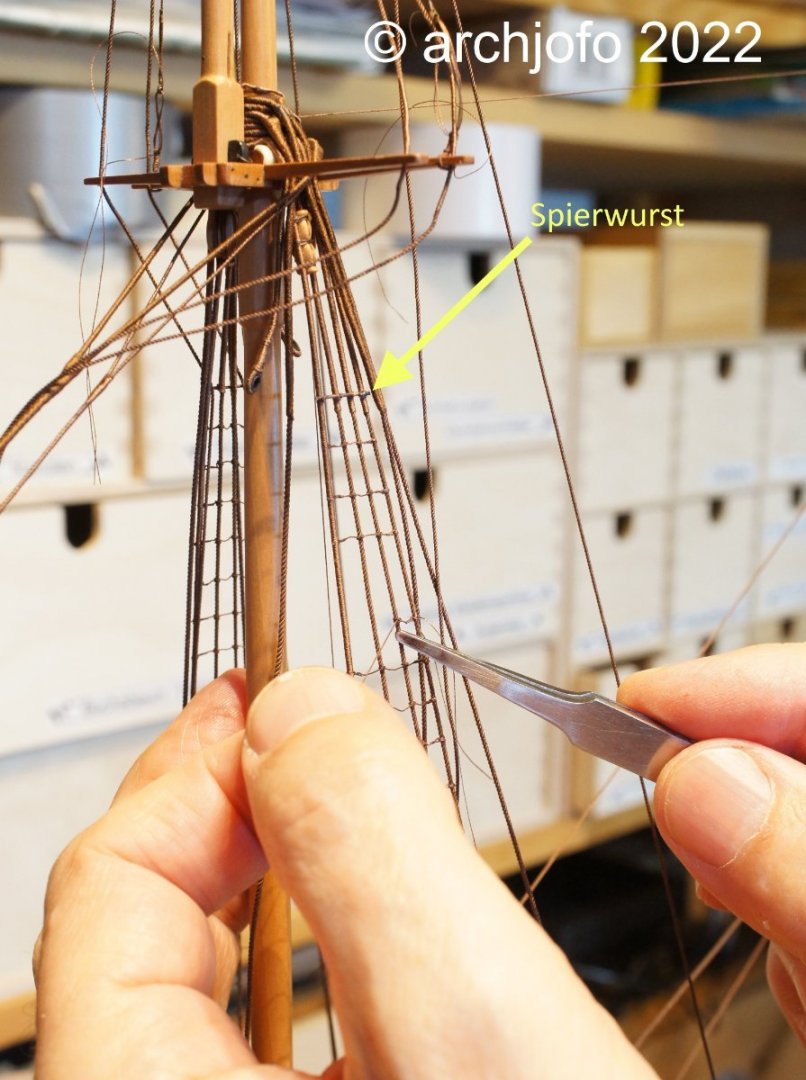
So the chapter -ratlines for the main topmast shrouds- is done: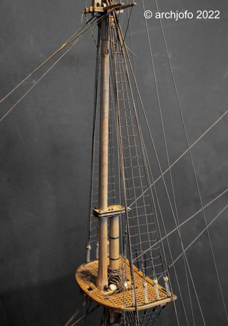
Soon I will continue with the ratlines for the fore topmast shrouds to finally close the chapter -ratlines- for this model.
To be continued ... -
-
Finest detail work !
Very nice rigging work.
This is a wonderful model.- Mirabell61, Dave_E and Dali
-
3


La Créole 1827 by archjofo - Scale 1/48 - French corvette
in - Build logs for subjects built 1801 - 1850
Posted · Edited by archjofo
@French Mr Bean
@Gahm
@jdbondy
@dvm27
Hello,
Thank you in advance for your nice comments and the many "likes".
I am always happy and motivated by positive feedback. Constructive criticism and suggestions are still very welcome.
Greg, I'm also very glad that my rigging inspires you.
Continuation: Standing rigging for jib and outer jib boom - Bâton de foc et bâton de clinfoc
First I had to attach the jib boom. I lined the jib boom passage in the cap of the bowsprit with a specially split leather (d=0.2 mm). The jib boom was placed on the prepared wooden pad or spacer so that it runs parallel to the bowsprit. Then I lashed the jib boom to the bowsprit analogous to bowsprit gammoning.
I added small details to the cap, as can be seen in the last picture. These are single blocks (l = 3.5 mm) on each side for the bowlines of the fore topsail. Next to the block you can also see the leather lining mentioned at the beginning.
Sequel follows …