Jump to content

Recommended Posts

Posted

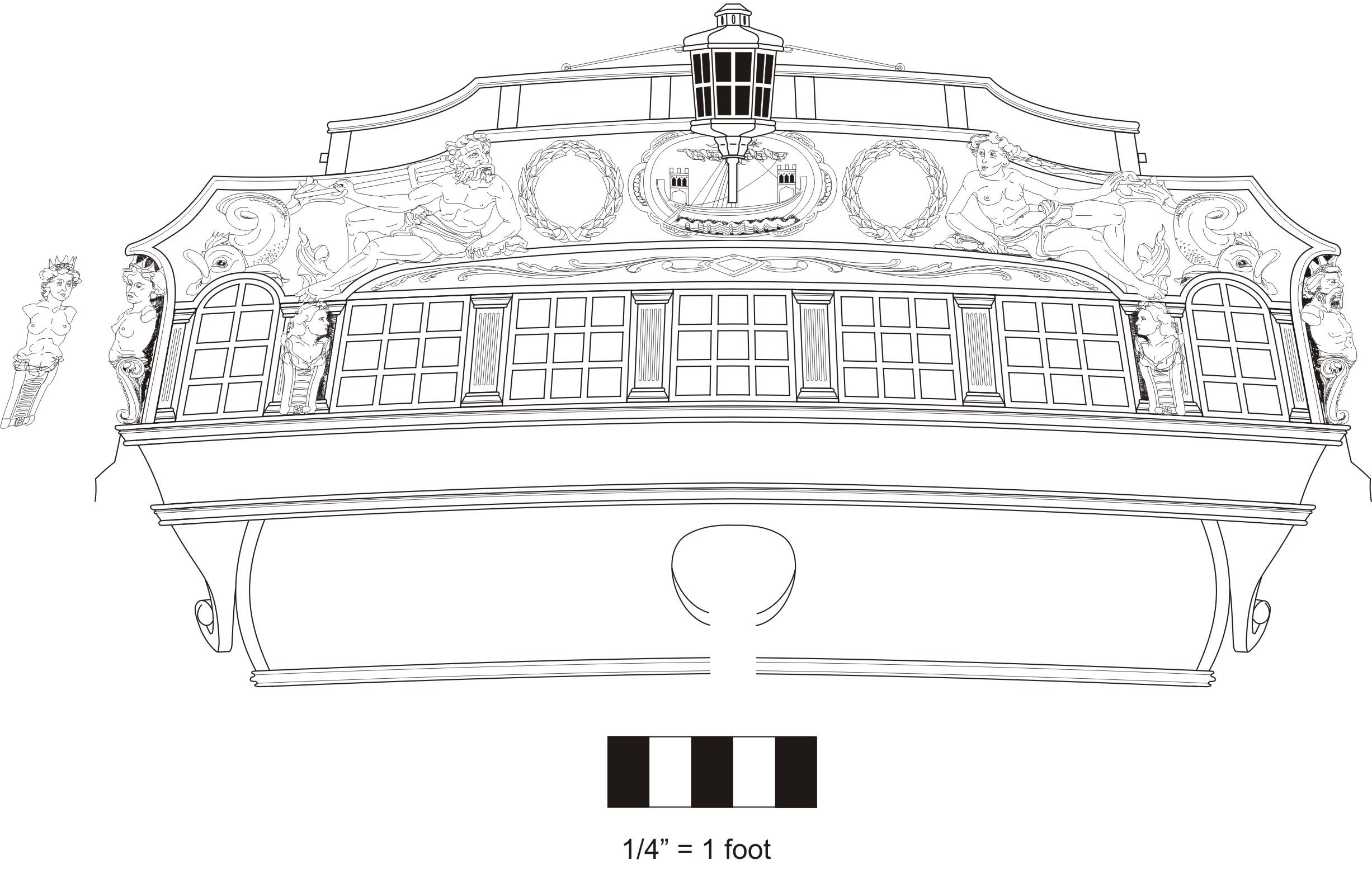
Yes they are not shown on the draft or the cont model but I think they would have been there.   The standards are usually  not shown on original drafts.  At least most that I have seen.  So this will be an optional detail but one I will be adding to my model for sure.


Chuck

Posted


Laser cut template for marking the height of the stern frames.  Now I must admit an error in judgement.  Not that this will be terribly difficult for me do,but  this would have probably been easier to do before the qdeck rails were added.  
 

So just a suggestion….and I will make the monograph chapter reflect this.  The stern frames are best cut down before you start on the qdeck railings port and starboard.


I have already cut down the stern frames using a sharp #11 blade.  Slicing a little at a time.  Then sanding down to my pencil lines made using this template. Note how the transom rail will be the same height as the qdeck fancy rail where the two meet.  Hence the difficulty in surgically cutting away those outer stern frames.


I am happy to report however,  that it all came out splendidly.  Photos of that shortly.  
 

so remember….This step first!!

8F17B3CE-0059-4568-9A96-F2E15FF6F279.jpeg

Posted

Just a another point here with the transom rail.  On the contemporary model the qdeck top rail is oddly higher them the transom rail.   You can always do this but the original drafts dont reflect this detail.   


Here is an oddly presented photo of that detail on the cont model.  It just doesnt look right to my eye and so I will attempt to make the transom rail flush with the top rail of the qdeck.


DSCF5528.JPG


In addition.....this photo shows a beaded edge to the top rail of the transom.   This will be added to our model as well.  More photos to come.


DSCF5484.JPG


Posted

If you remember, I used the provided laser cut template to mark the height of the stern frames.


8F17B3CE-0059-4568-9A96-F2E15FF6F279.jpeg


Then I cut them down most of the way with sharp chisels and a #11 blade.  I followed that up with sanding them down to their final height.


The first part of the cap added was the laser cut center section.  It is 1/16" thick.  This piece has a gentle curve to it when viewed from above to follow the curve of the transom.  This piece was centered and glued in position.  I also cleaned up both ends to make them neat and tidy to accept the pieces we will glue into position next.


You can see the center section glued into place below.  In addition the first outer section is glued on as well.  Note how it is much wider than the center length.  This will allow you to draw and MATCH the curve of the transom when viewed from above.  I am not really stressing the sanding of char here because that will be taken care of once you reduce those outer pieces.   You will be reducing them to the same width while maintaining the same graceful curve.


transomcap4.jpg

Once you finish both sides, you can sand it all with a fine grit sandpaper to prep for painting.  Then paint the whole thing black.   Sanding made a lot of dust so remember to clean that all away before you start painting.  You want the best quality painted surface as possible.


Here are some pictures after the cap was completed and painted.  This really ties everything together well.


transomcap10.jpg


transomcap6.jpg

transomcap7.jpg


transomcap9.jpg


Posted

Thank You....A few fairleads along the inboard bulwarks are next up along with eyebolts and metal work.   Lastly the 8 guns on the qdeck will be added to complete chapter 10.


Posted

12 for sure.....but if one of them gets too long I may stretch it to lucky number 13.   And then after that a sep. mini kit for the 30 ft barge and its display on the model.

Posted

It depends on the wood.  A harder wood like boxwood I just paint directly on the surface after sanding it very very smooth.  Softer wood like cedar, is sanded as well but then I apply a coat of sanding sealer.   I also still sand between many coats of thinned paint.  I sand the paint and if I get to bare wood I have gone too far.   I use 600 grit or even finer grit at that stage.

Posted

For us only dreaming about getting to this point….did I miss it somewhere, how do I determine the planking butt shift pattern below the wales? …I know, so long ago for many of you😏

Regards,

Glenn


Current Build: Royal Barge, Medway Long Boat
Completed Builds: HMS Winchelsea HM Flirt (paused) HM Cutter CheerfulLady NelsonAmati HMS Vanguard,  
HMS Pegasus, Fair American, HM Granado, HM Pickle, AVS, Pride of Baltimore, Bluenose

Posted (edited)

I don’t recall where the instructions are to corroborate this, but a full length plank is 8 bulkheads long.  The shift is two bulkheads, meaning the pattern repeats every four strakes.  Look at page 14 of the chapter 2 monograph to see Chuck’s as an example.  Also, find Chuck’s YouTube videos to learn more.  I hope that helps.  Here is the thread on planking.  It has links to the videos, too.


Edited by Matt D
Added link

Current Build:

HMS Winchelsea 1:48 (Group Project)


Completed Builds:

Virginia 1819 Artesania Latina - 1:41 


Posted
1 hour ago, Matt D said:

a full length plank is 8 bulkheads long.  The shift is two bulkheads, meaning the pattern repeats every four strakes.

Thank you, this helps. I was thinking I may have missed a .pdf, it was laid out on the plans for Cheerful. 

Regards,

Glenn


Current Build: Royal Barge, Medway Long Boat
Completed Builds: HMS Winchelsea HM Flirt (paused) HM Cutter CheerfulLady NelsonAmati HMS Vanguard,  
HMS Pegasus, Fair American, HM Granado, HM Pickle, AVS, Pride of Baltimore, Bluenose

Posted

One of the last items to make for chapter ten are these fairleads that are positioned along the inboard side of the qdeck bulwarks.  They are basically like timberheads with a sheave.  They are used to belay the falls for the upper ropes of the main mast and mizzen.   


Now I originally placed I believe 5 of these on each side.  But recently I have learned there were only three.  I also now have better images of the contemporary model which also confirms this.   So if you are examining the plans.  You will ONLY be adding the aft-most three of these on both sides.   This matches the Winnie contemporary model along with several  others.  


They are easy to make and laser cut in two layers.   Just glue the thinner 1/32" thick layer (this actually becomes the back side against the bulwarks) to the thicker layer with the sheave etched in it.  Then sand the char and even out the sides.  You will have to shape the top of the timberhead as the others with a sharp blade.   Also round off the bottom front edge as shown below.   Remember to round off the right side...….the front side.


qdecktimberheads.jpg

These are then glued to the inboard side of the bulwarks.  They are exactly opposite the timberheads on the rail as you can see.  This makes positioning them easy enough.  They should be vertical.   


These are laser cut with the tops and bottoms on an angle.  So there are port and starboard versions of these.  Make sure you select the right ones for each side.


Here you can see them in position on my model.


qdecktimberheads1.jpg

Next up I will make the eyebolts and rings for the guns.   These will be placed on the inboard side of the rail.  Check the plans.   Luckily we only have 8 to make so not as bas as making all of the eye bolts for the gun deck.  In addition....because of the how we are planking the quarter deck,  there will be no place to secure the eyebolts and split rings on deck.  They would have fallen where we show the planking removed on the qdeck.


Making the 8 six pounders and carriages will complete this chapter.  They are sold separately as before.  They are 1 9/16" long.   


I will place all 8 on the qdeck but be aware that in actuality only six would be placed there.  The other two would have been on the fcastle.   But as shown on many contemporary models they seem to place them all on the qdeck.  My guess is they want to fill that dead space near the transom.   


Chuck

Posted (edited)

Which is the correct carriage size for the 1 9/16 barrels?


I probably missed it, is the binnacle a mini-kit, I don’t see one on SSMS?

Edited by glbarlow

Regards,

Glenn


Current Build: Royal Barge, Medway Long Boat
Completed Builds: HMS Winchelsea HM Flirt (paused) HM Cutter CheerfulLady NelsonAmati HMS Vanguard,  
HMS Pegasus, Fair American, HM Granado, HM Pickle, AVS, Pride of Baltimore, Bluenose

Posted

Those carriages havent been made yet. Its on the list.  The Binnacle parts are included in chapter 10.  The binnacle is not a mini kit, although it may become one soon so folks can use it on other appropriate models.  
 

….and yes,  if you examine the plans you will see swivel guns and mounts.  That is part of chapter 11.   

Posted

There is an 1/8” wide strip atop the quarterdeck bulkheads, 5/32” bulkhead thickness at the bow and eventually 3/16” wide strips to guide fairing on all three sections. Clearly, the waist bulkheads are faired to the 3/16 wide guide strip, but is a 3/16 wide guide strip placed atop the 1/8 wide strip on the quarterdeck and is the bow section 5/32 only where it intersects the bollard? Your instructions are excellent but for some reason the sections dealing with final bulkhead thickness in the three areas is confusing my tiny brain.


Posted

Its different widths at different times.  Those quotes you posted are from different chapters.  You are reading too far ahead and the widths change depending on what inboard/outboard planking is added.   Just follow the instructions in a linear format. 
 

when you first start on the q deck you add the narrower strip.  No planking yet.  Then after planking its wider….the outboard planking being 3/64” thick.   Hence the now wider strip added to the cap.  Its different for each stage of construction which you are mixing up.

Inboard fairing isnt done until after the outboard planking is finished.  This is for a reason.  The outboard planking makes the area stronger so you wont break the framing.   It would be sanded too thin otherwise and be structurally weak.  You should NOT be fairing inboard to the final thickness before planking.   So just stick with that timeline and you will be fine.  Otherwise you will certainly run into serious issues later.


Posted

I just saw your build log and since you faired the bow inboard and out prior to planking, you will certainly have to be very careful.   As you plank up there you will now be in danger of distorting the shape at the bow because the bulkhead frames are so thin.  You will end up with the incorrect shape.  This is why I write that you should wait until after planking is finished and the frames are thicker and stronger so they wont flex and distort.   At the bow you can remove some of the material to cleabn it up as I did.   You can do a general clean up inboard and start to even it out but I wouldnt reduce it to the final thickness yet.   


Just try not to deviate from the instructions moving forward.  Most that do end up with some serious problems to fix later on.   

Chuck

  • Recently Browsing   0 members

    • No registered users viewing this page.
×
×
  • Create New...