


chris watton
-
Posts
2,205 -
Joined
-
Last visited
Content Type
Profiles
Forums
Gallery
Events
Posts posted by chris watton
-
-
-
-
Fantastic model, very well done, it looks perfect!
-
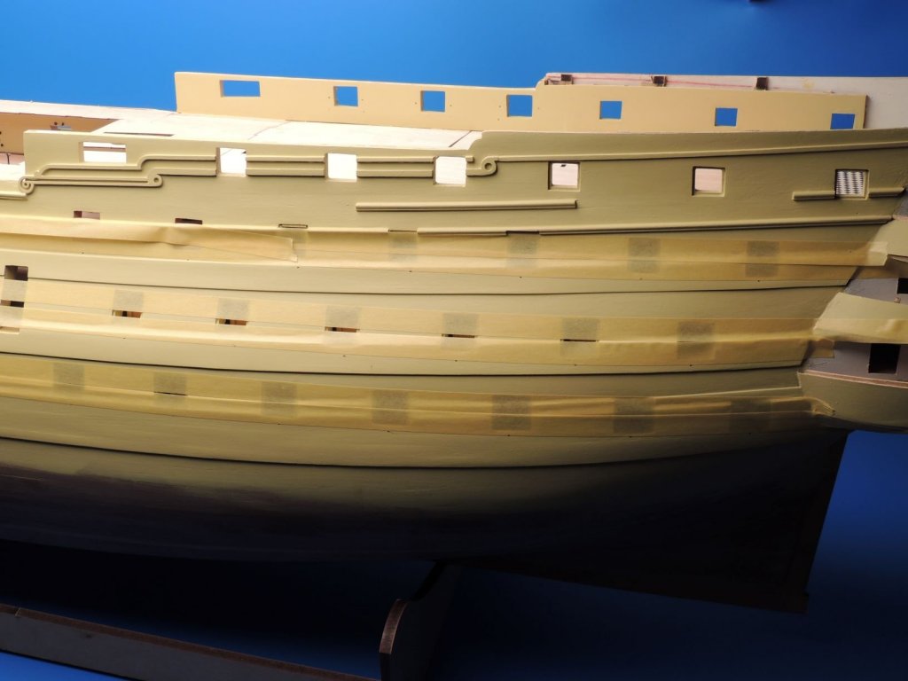
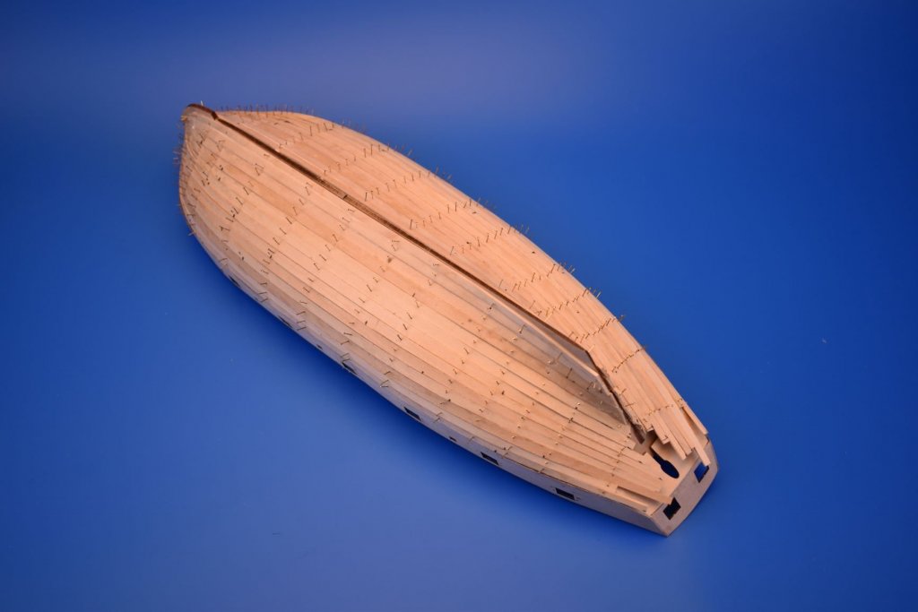
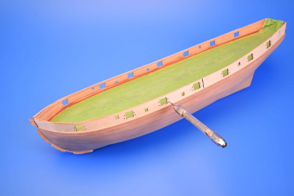
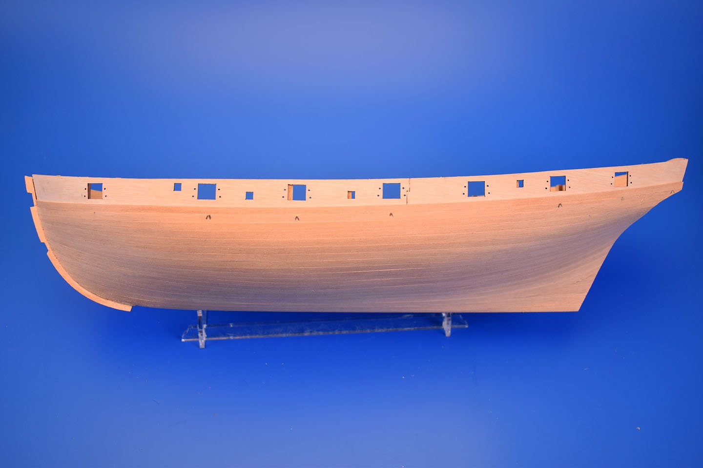
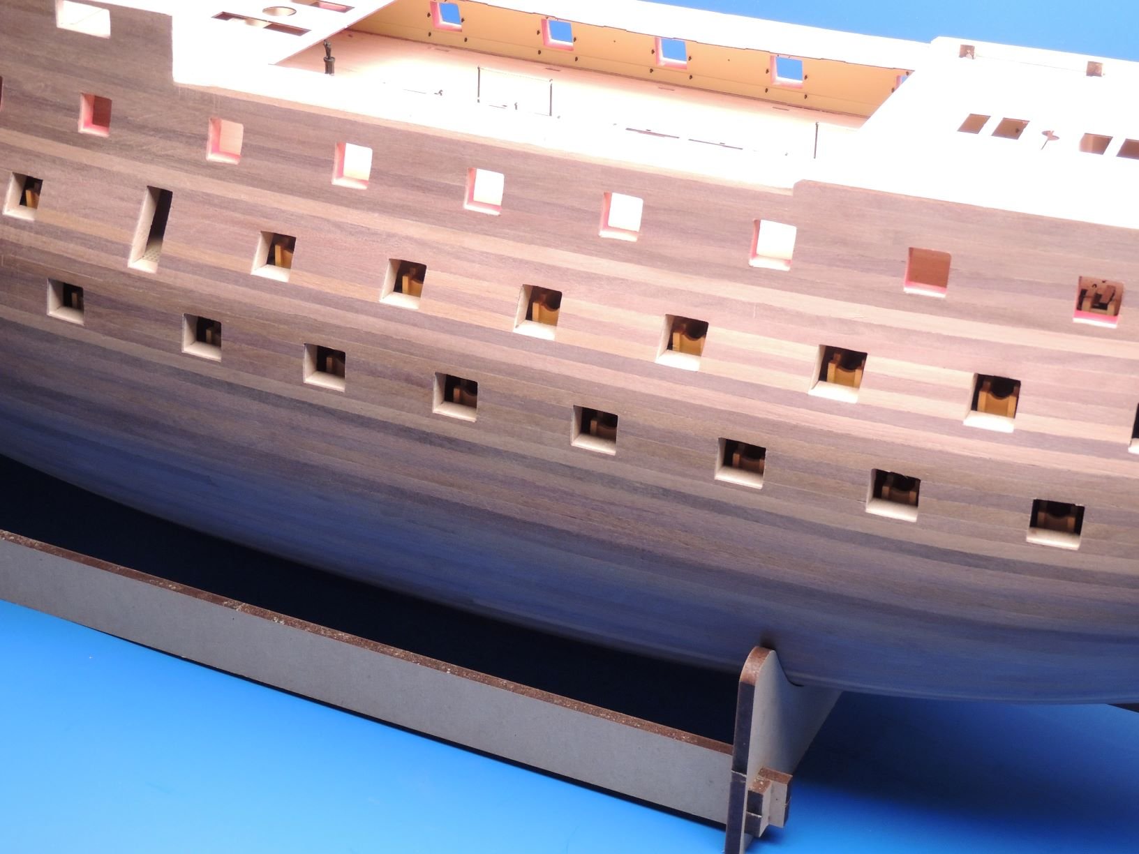
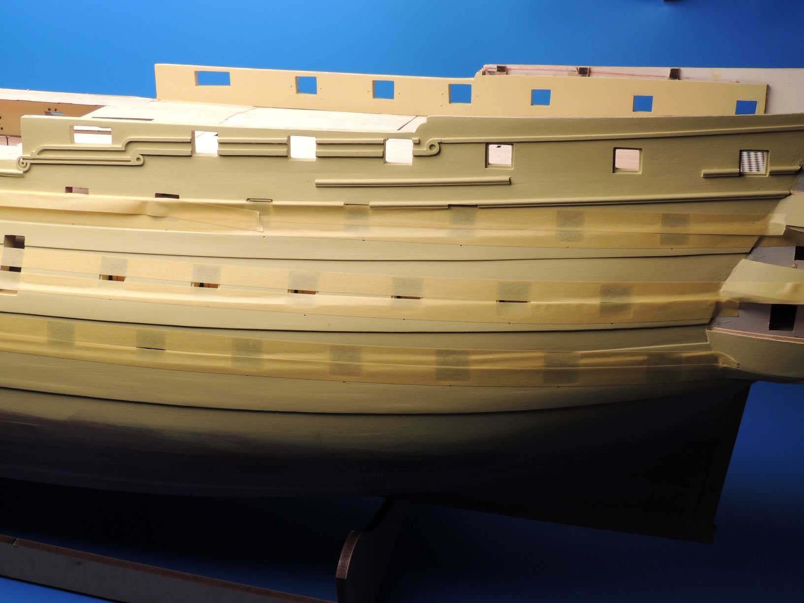
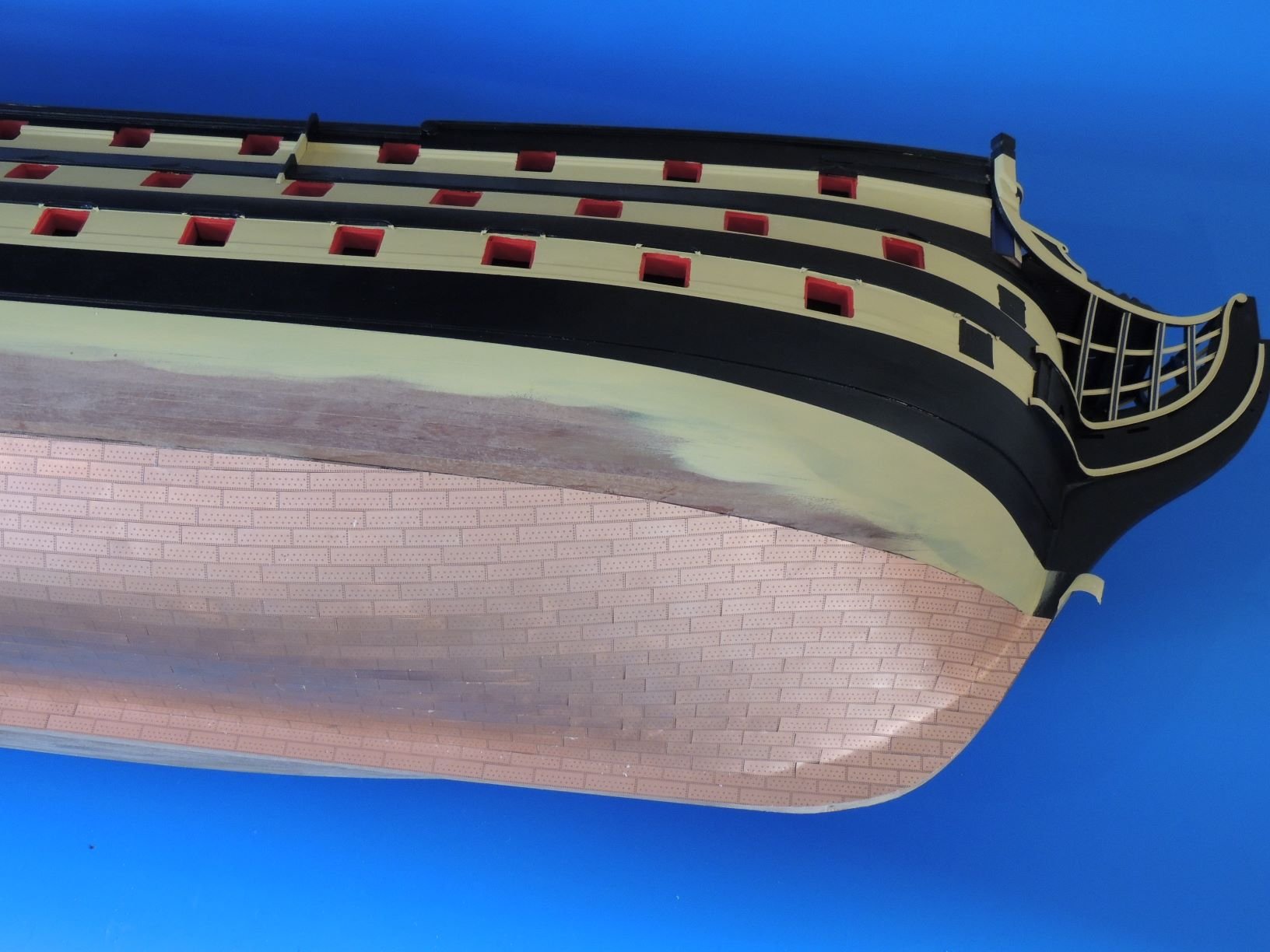
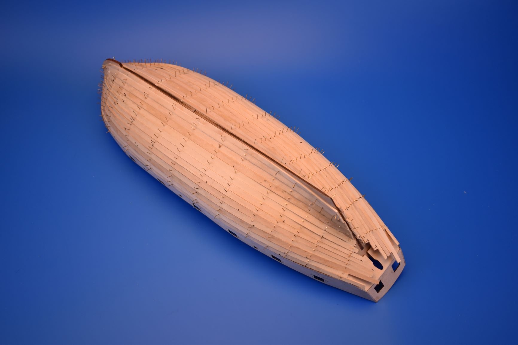
First planking sanded, ready for second planking. Won't win any prizes for planking perfection, but more than good enough for the basis for second planking, which I will do in Tanganyika for this one.
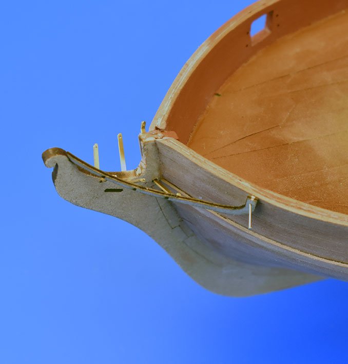
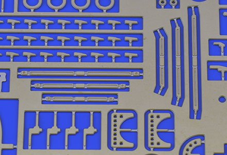
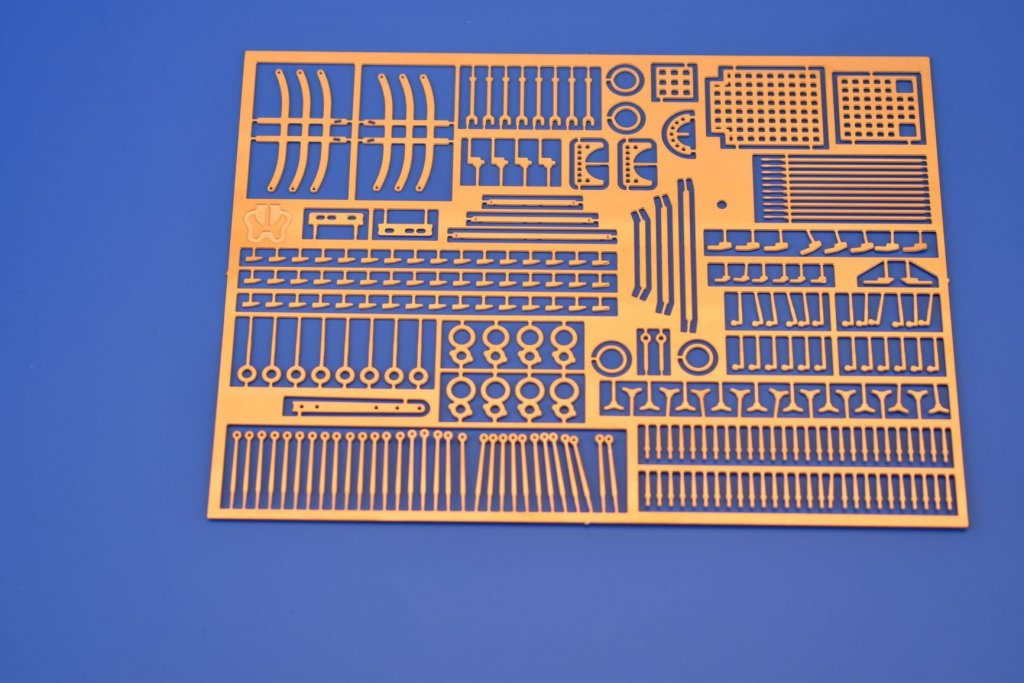
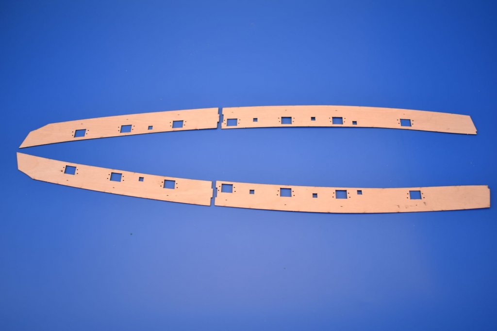
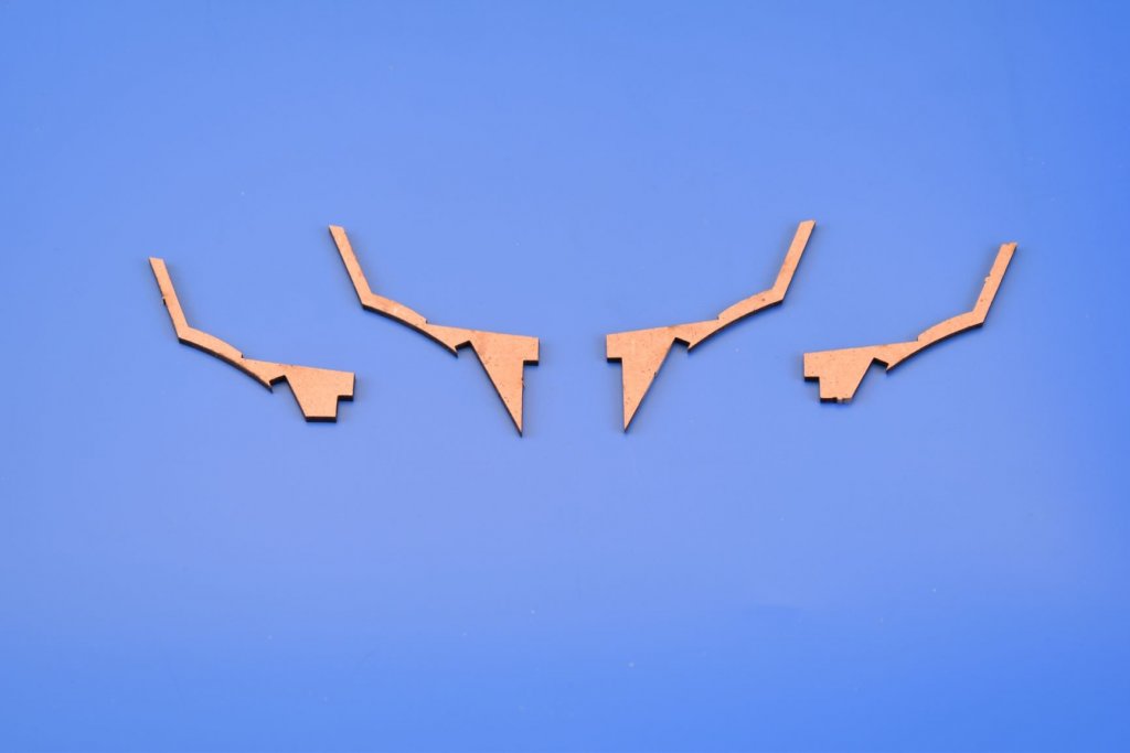
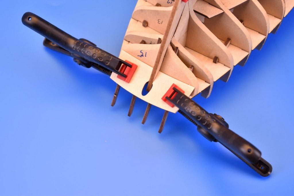
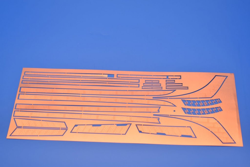
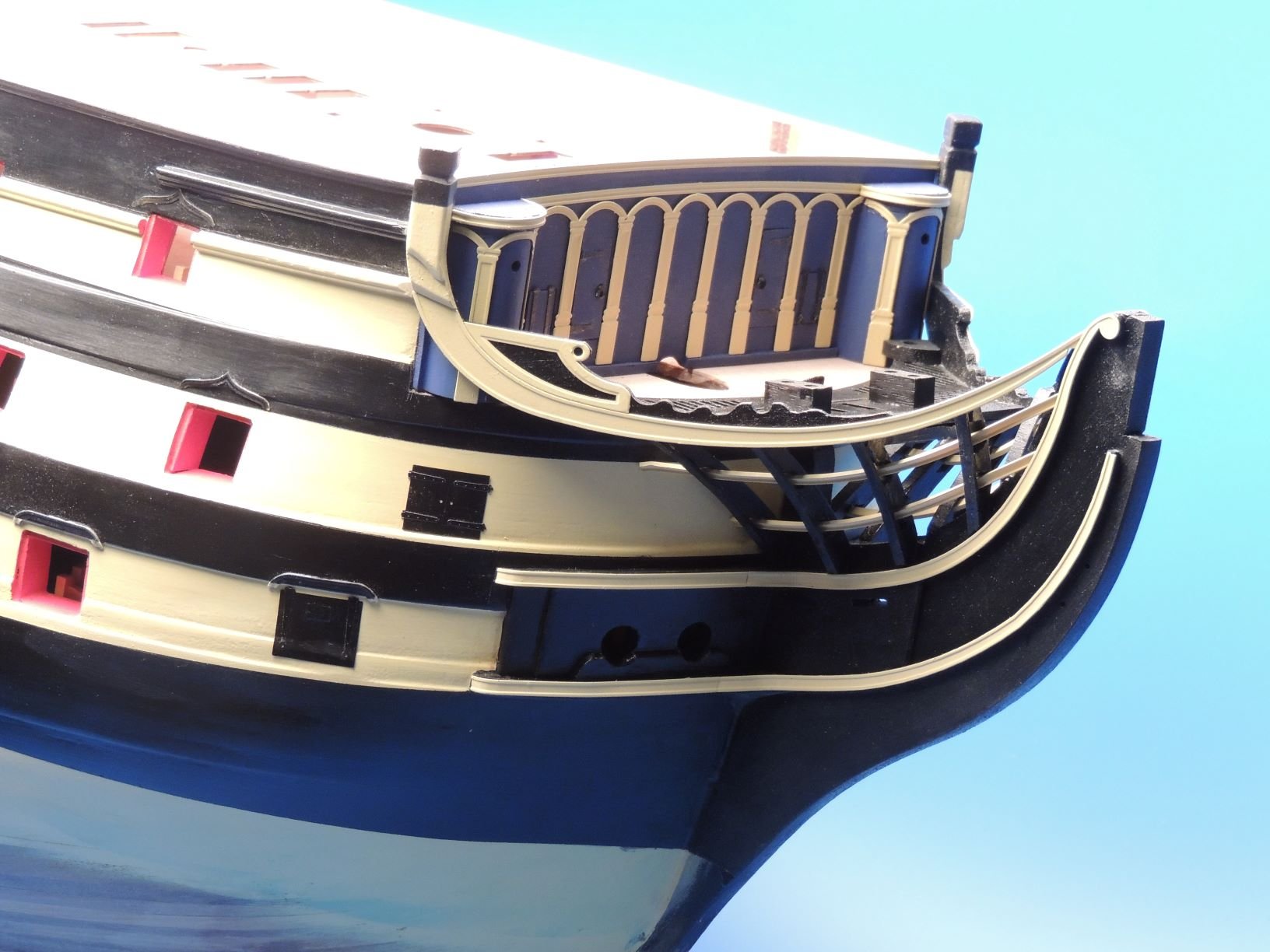
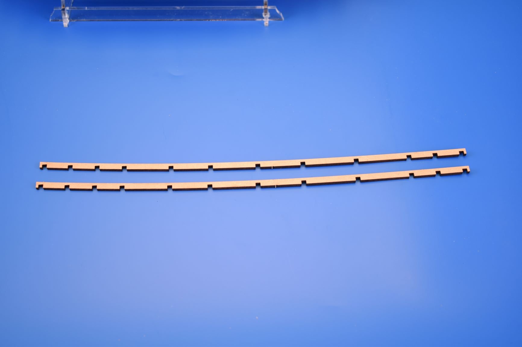
I think the toughest part of the build (for me at least) is trying to sort out the best way of doing the very fine vertical 'V' shaped headrails. They are only 1mm wide according to the original plans, and I hate having to make things like this too thick. With that in mind, I did two separate designs for the 'V' rails in 0.6mm PE (the two sets of long patterns in the PE pic), and in the other pic, I was trying one type last night (nothing glued, just checking everything connected as they should) On the real thing, these 'V' frames must have been nothing more than very 'scanty' timbers connected to the prow and headrail. I would like to keep that delicate look if possible.
- JpR62, Jim Rogers, paulsutcliffe and 18 others
-
 21
21
-
4 minutes ago, SpyGlass said:
Juat a query Chris - I notice that your lower strip curves away from the keel at the stern.
Is it the pic angle or is that the way you do it ?
It does, no need to plank the whole of the false keel area as the second planking will cover it. if I planked the whole lot, all I would end up doing is sanding it all back off again.
-
-
1 hour ago, vossy said:
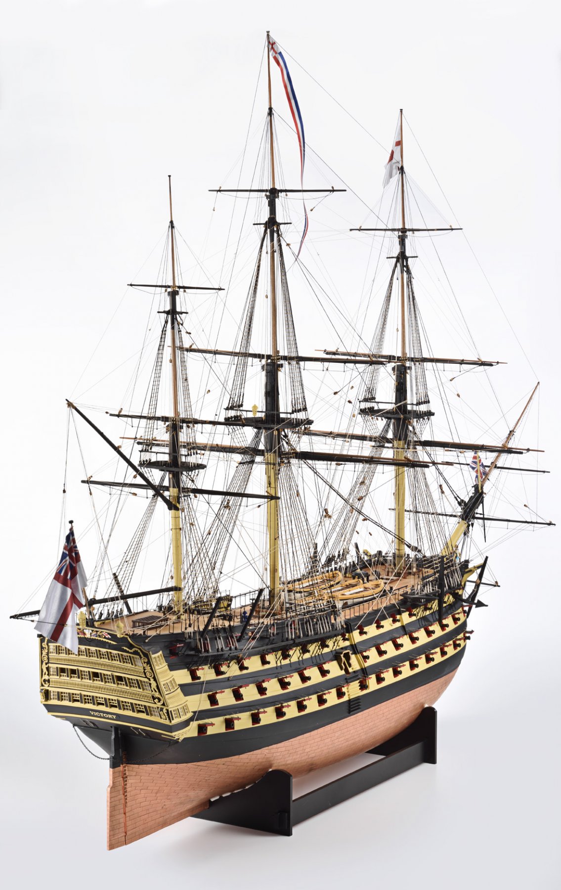
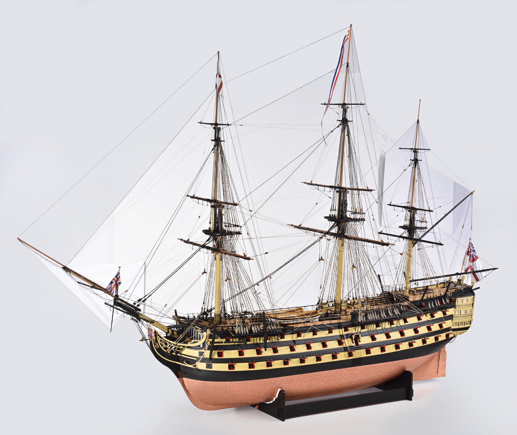
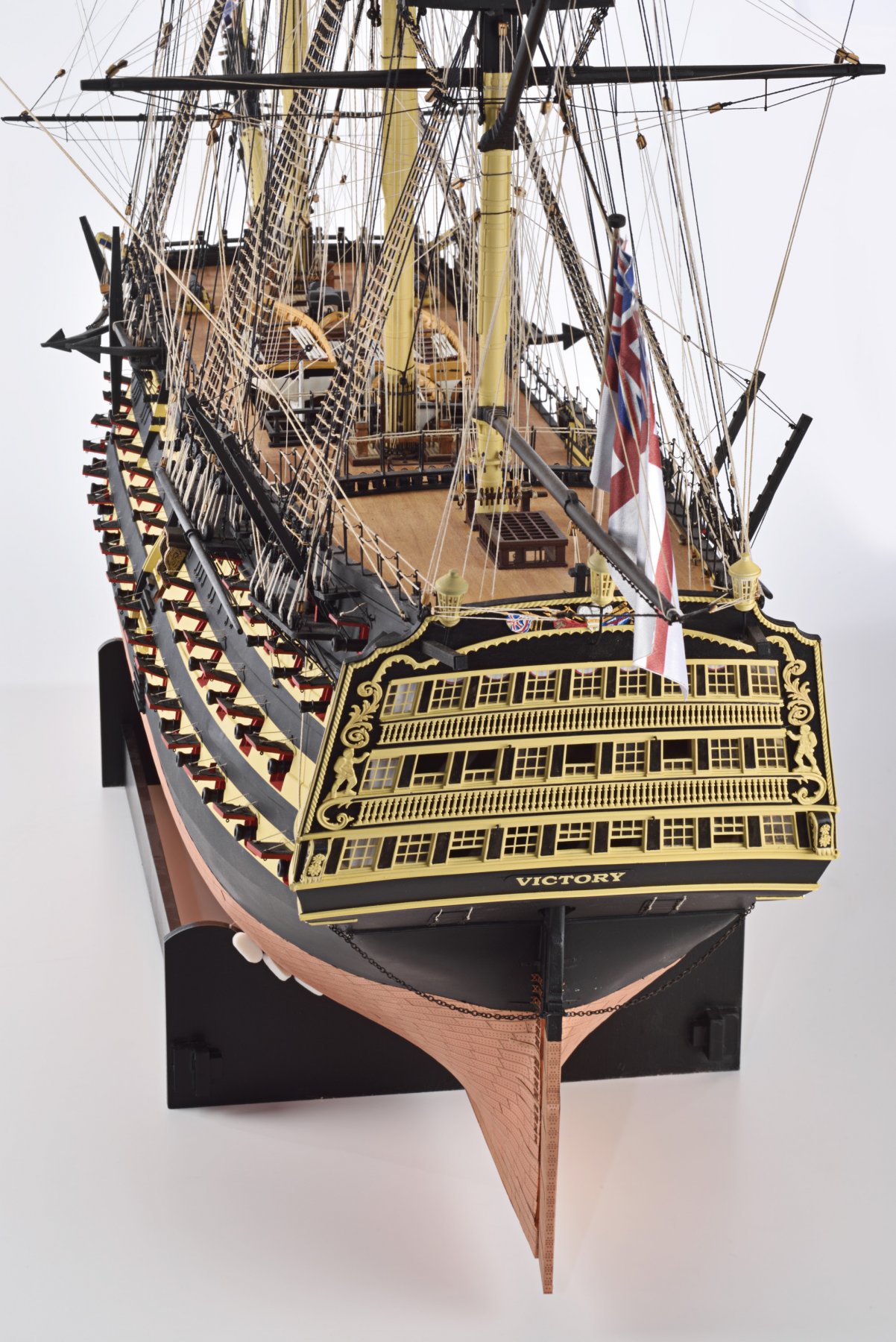
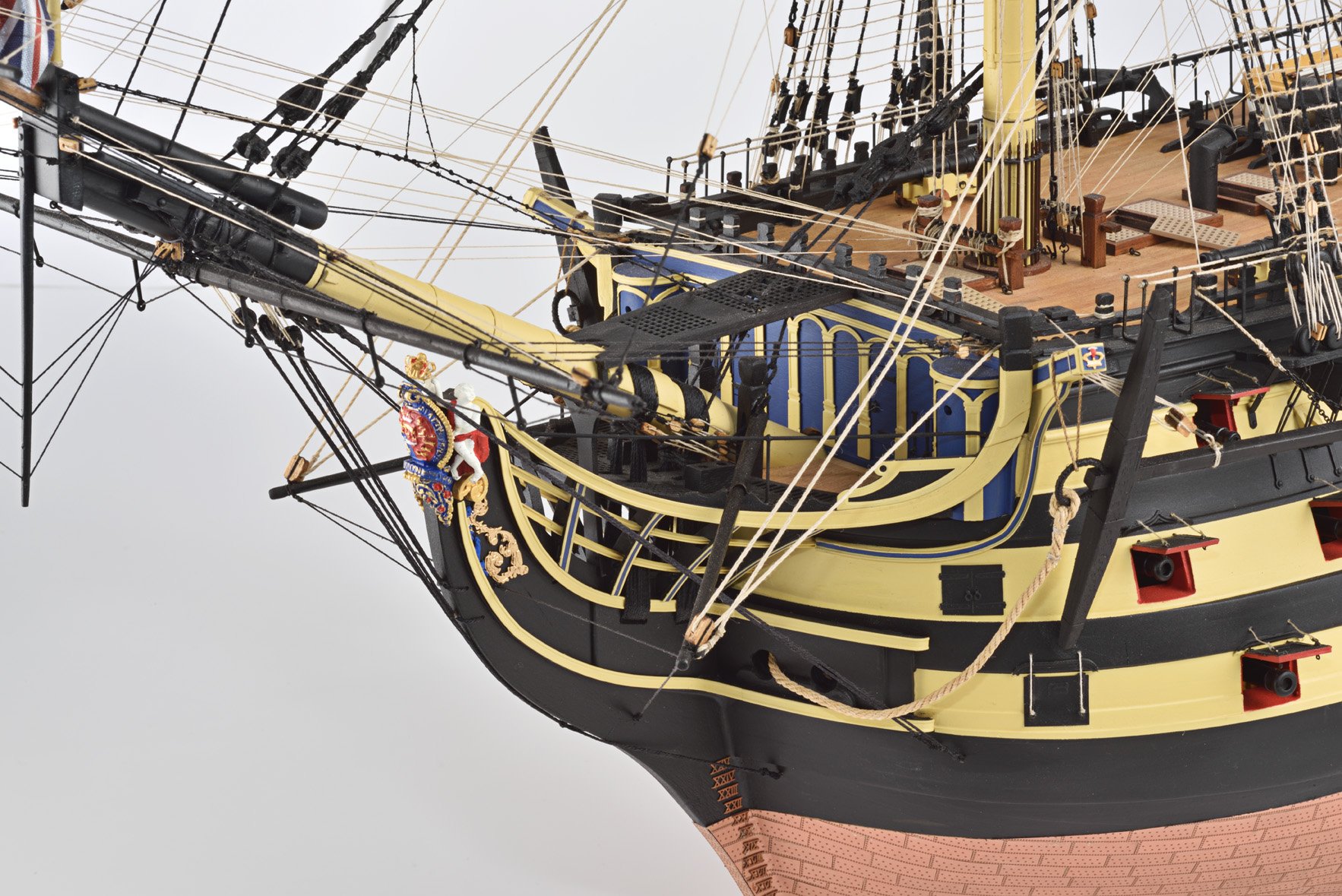
Hey Chris, are you able to post more pictures of your Amati Victory in various stages? Totally understand if for moral/legal reasons you cant, but if you don't ask, you don't get.
Cheers
Chris
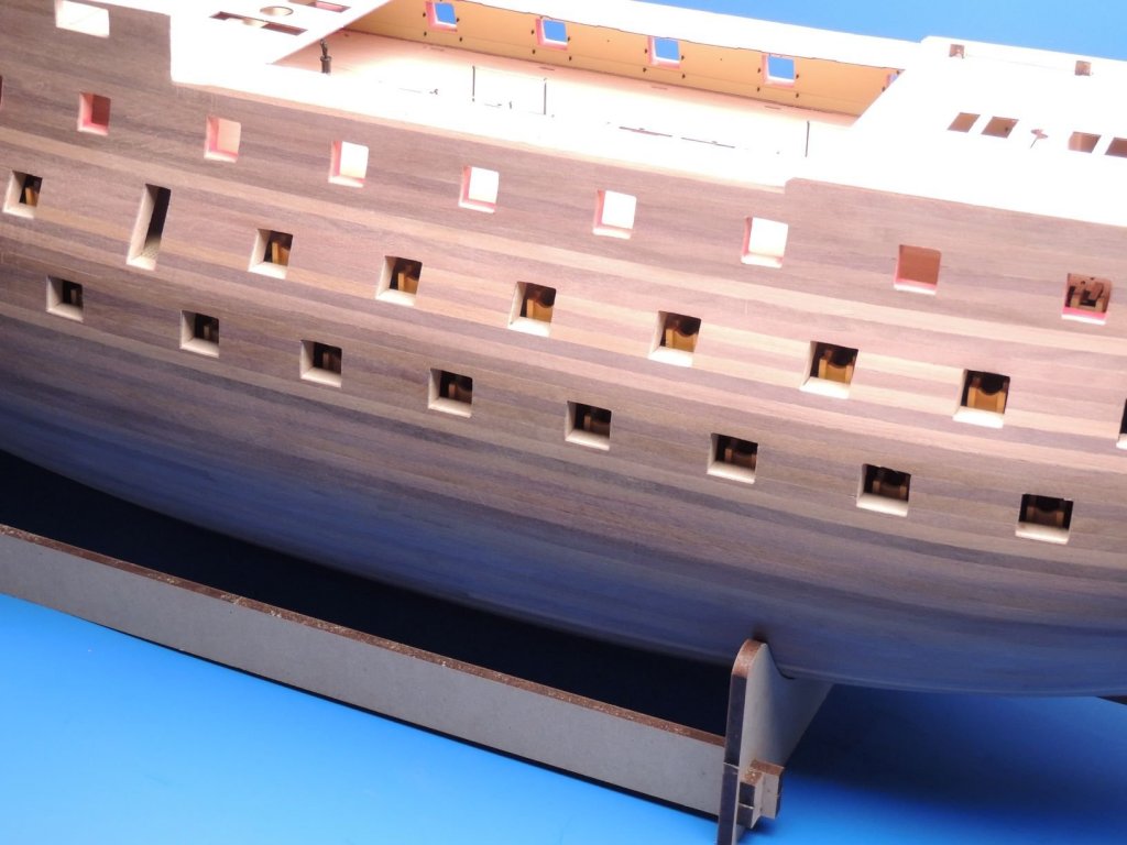
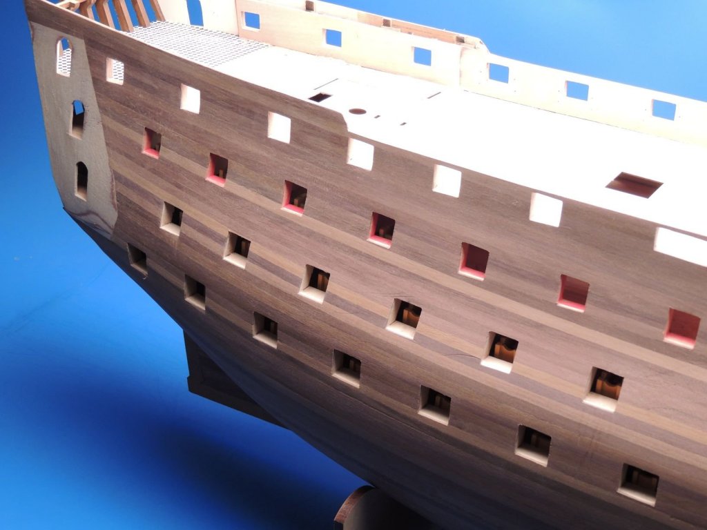
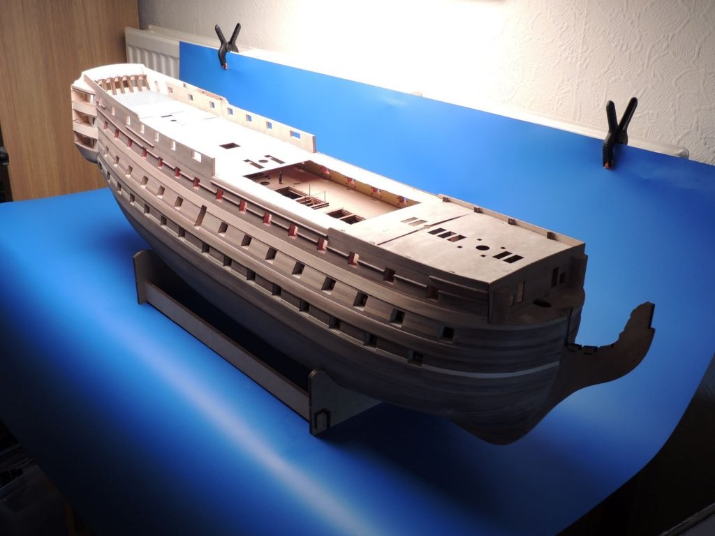
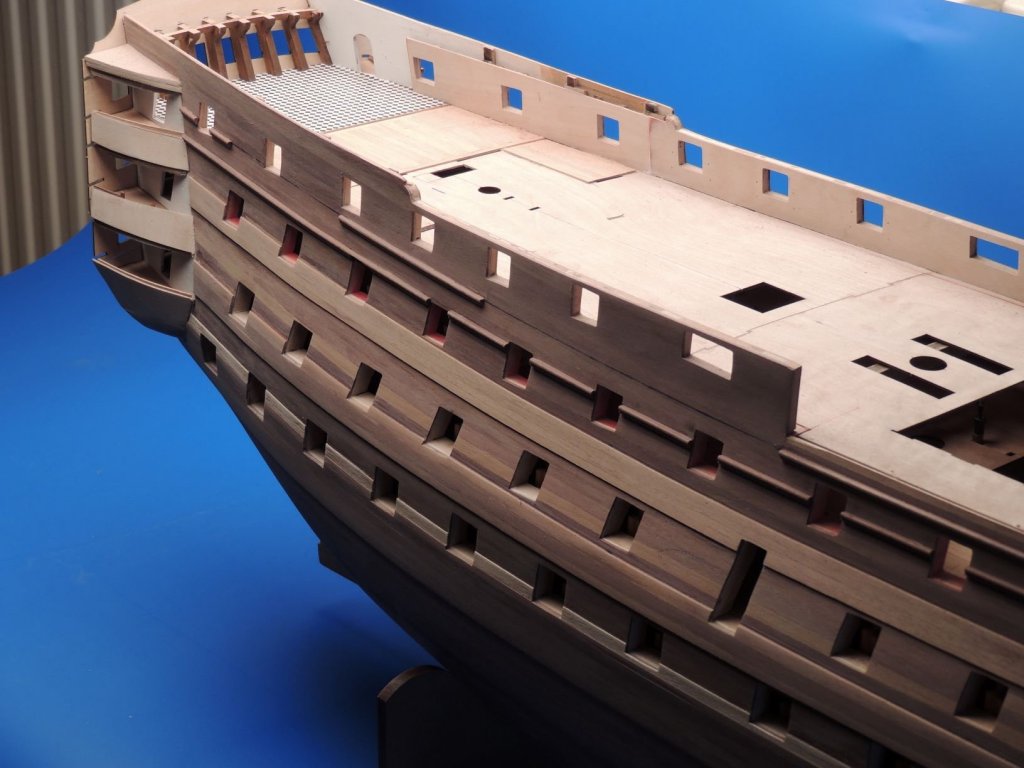
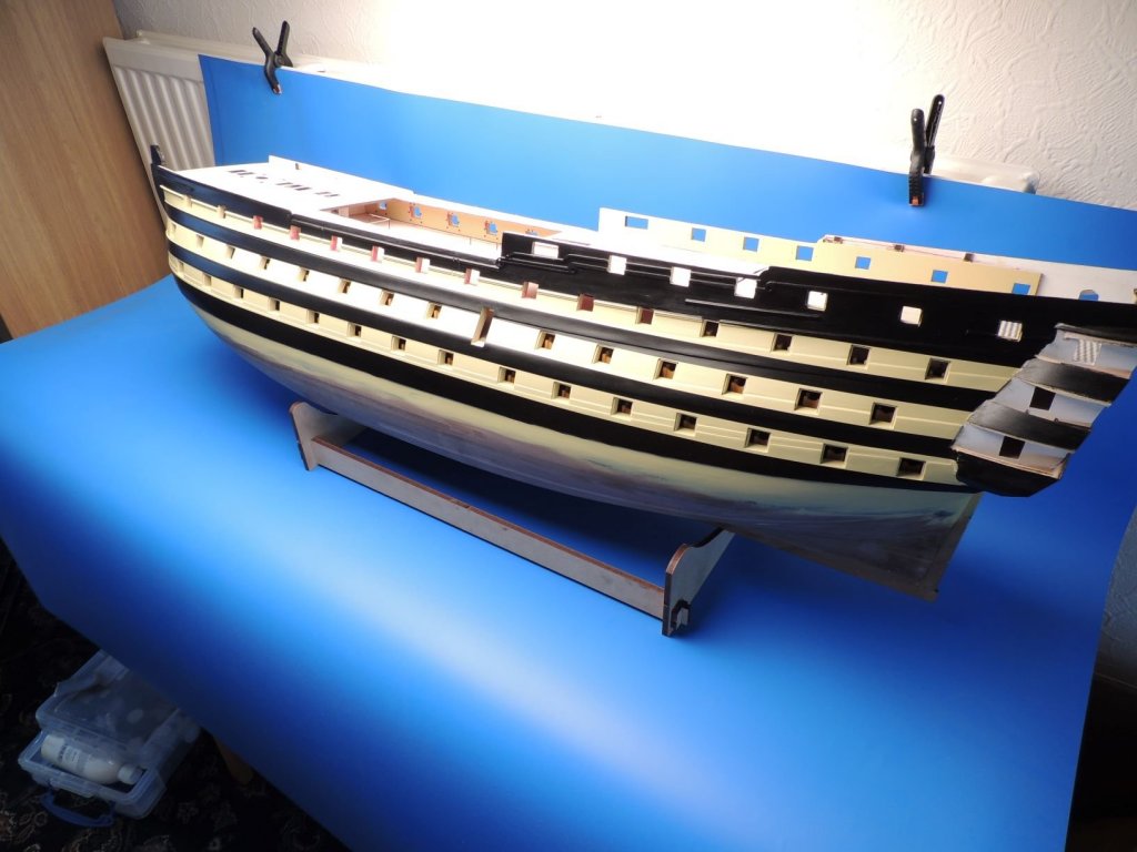
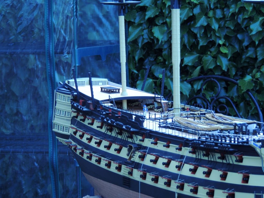
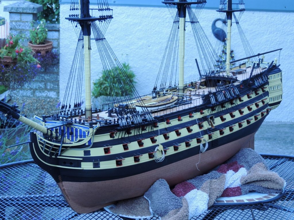
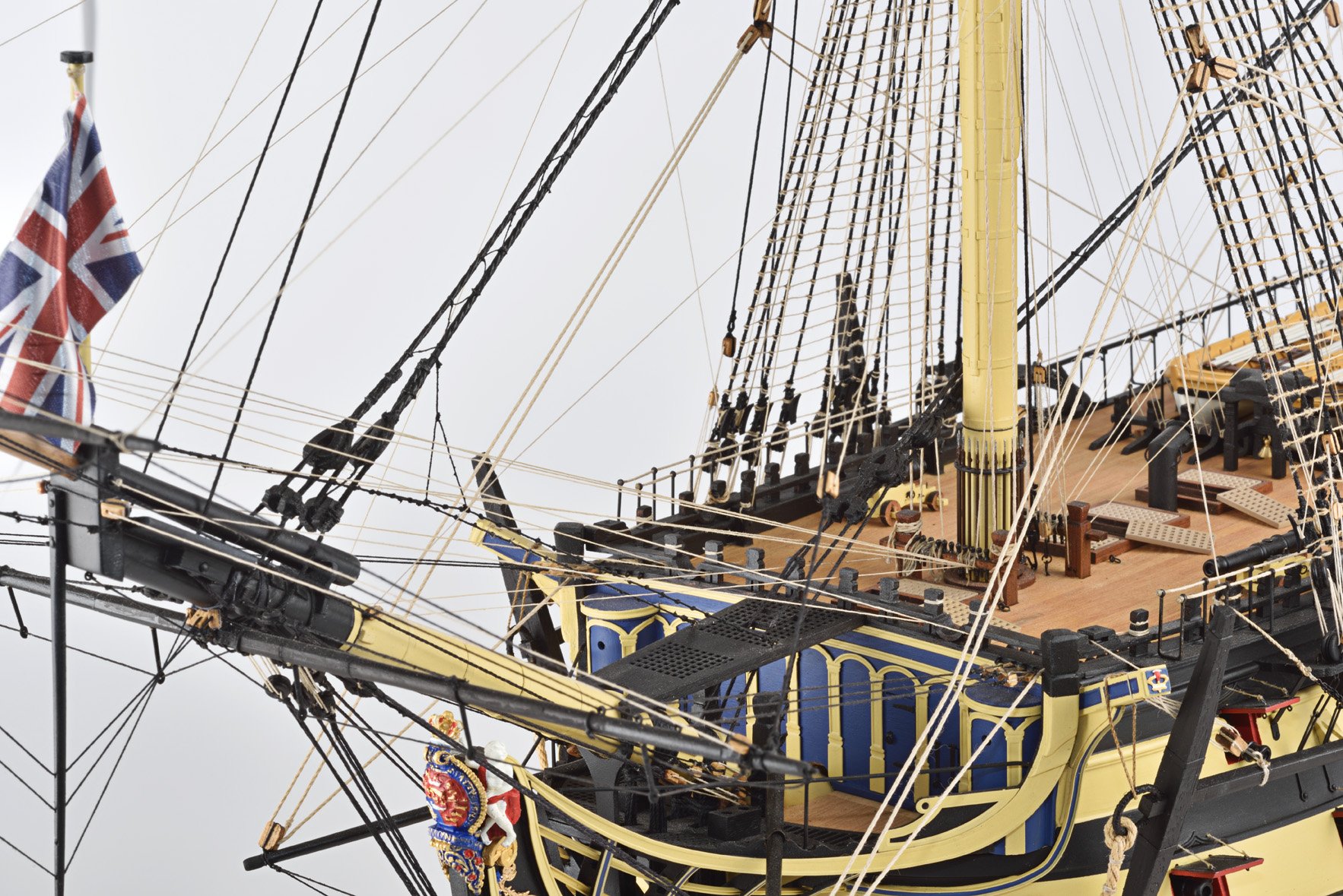
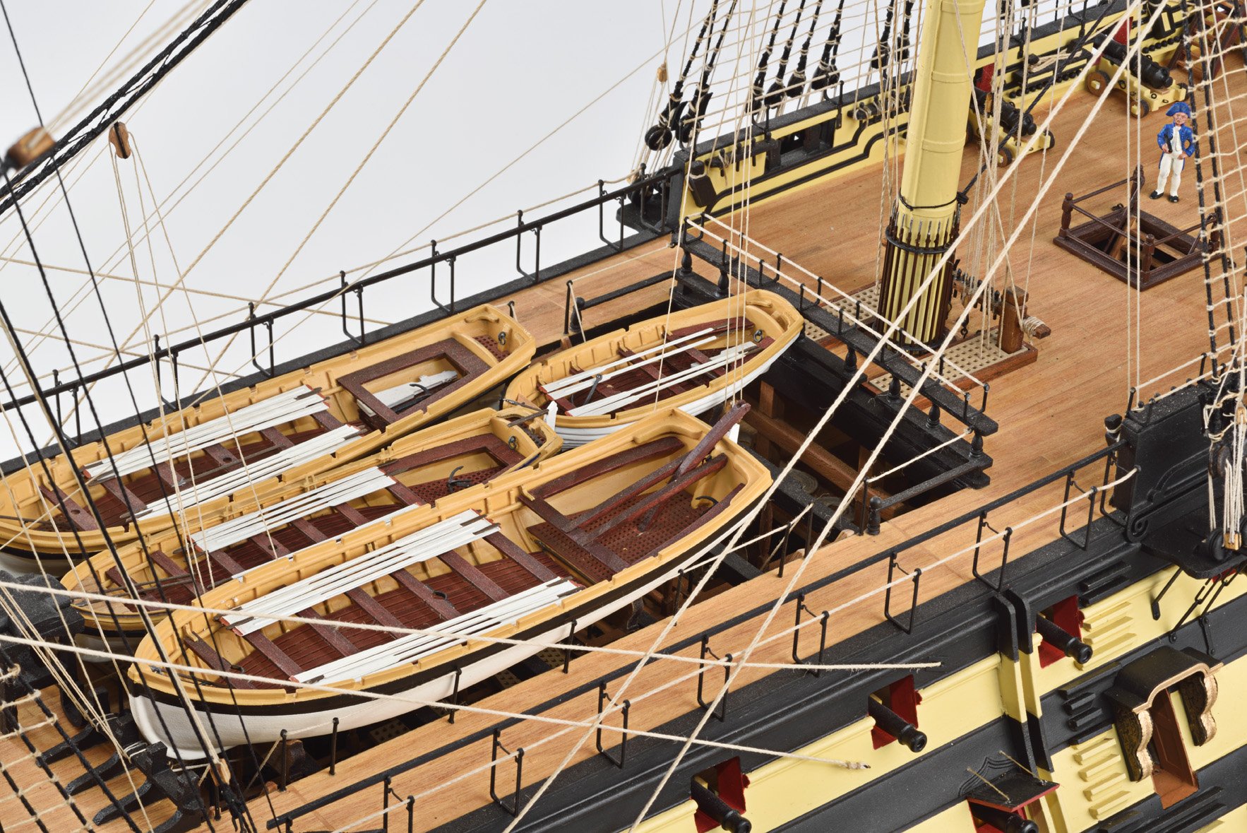
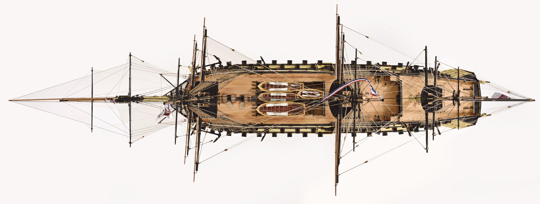
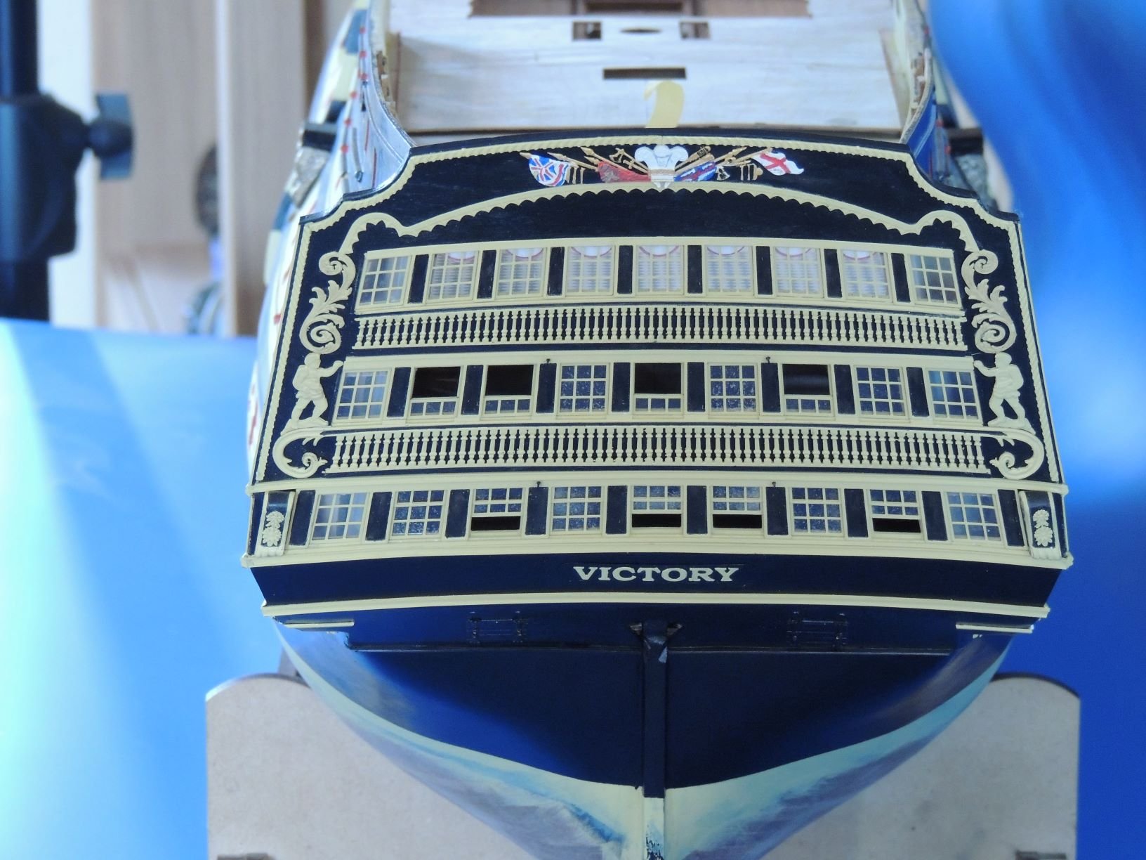
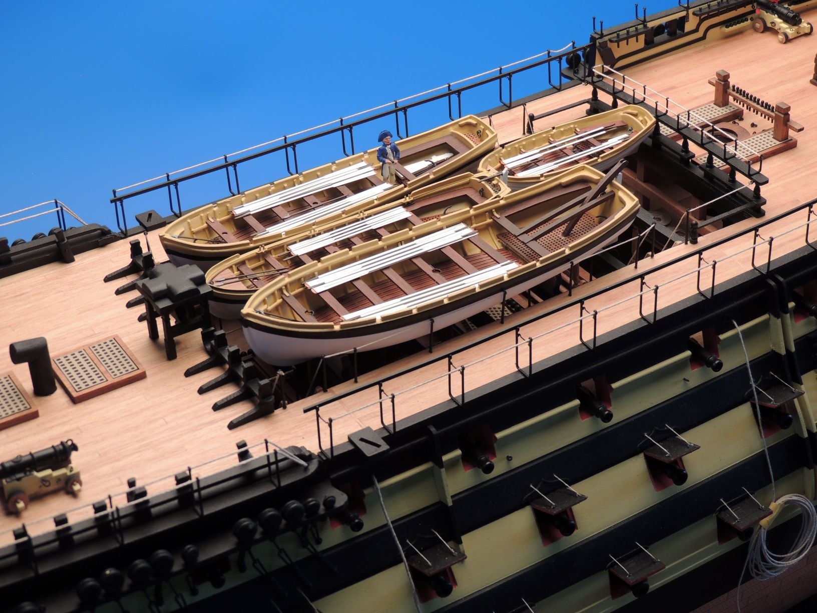
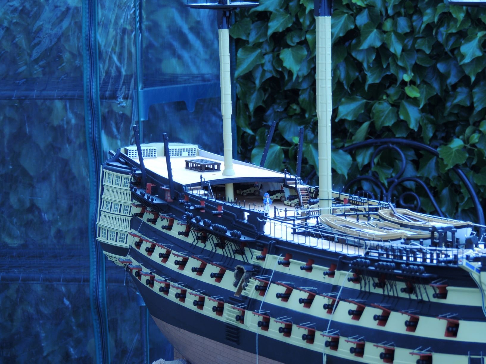
Here you go, some I don't think I have shown before..


- DelF, Landlubber Mike, Jonny 007 and 14 others
-
17
-
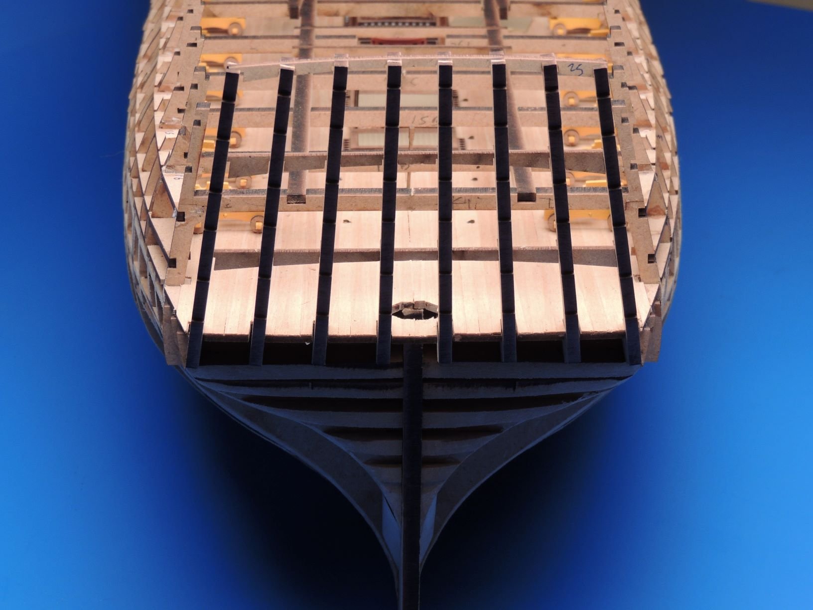
Today, well, this afternoon, I started and finished the first planking, no drama. Will leave until tomorrow to sand it so it looks a lot more presentable...
- druxey, ErnieL, Ryland Craze and 15 others
-
18
-
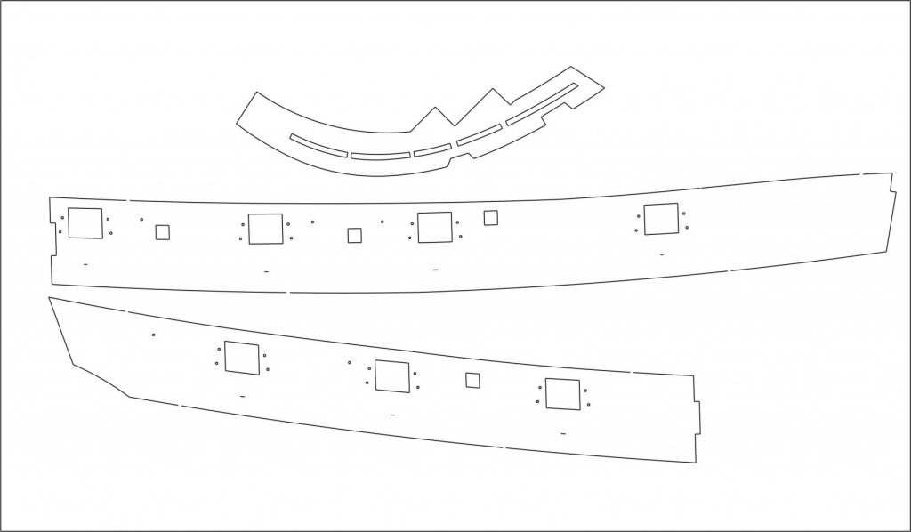
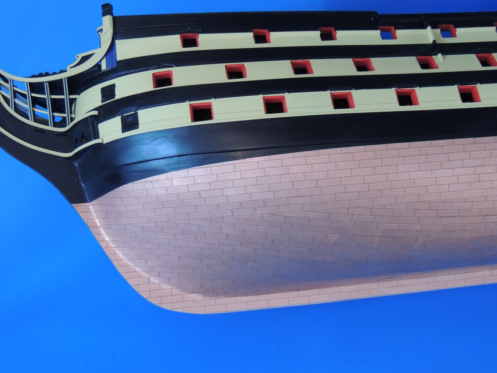
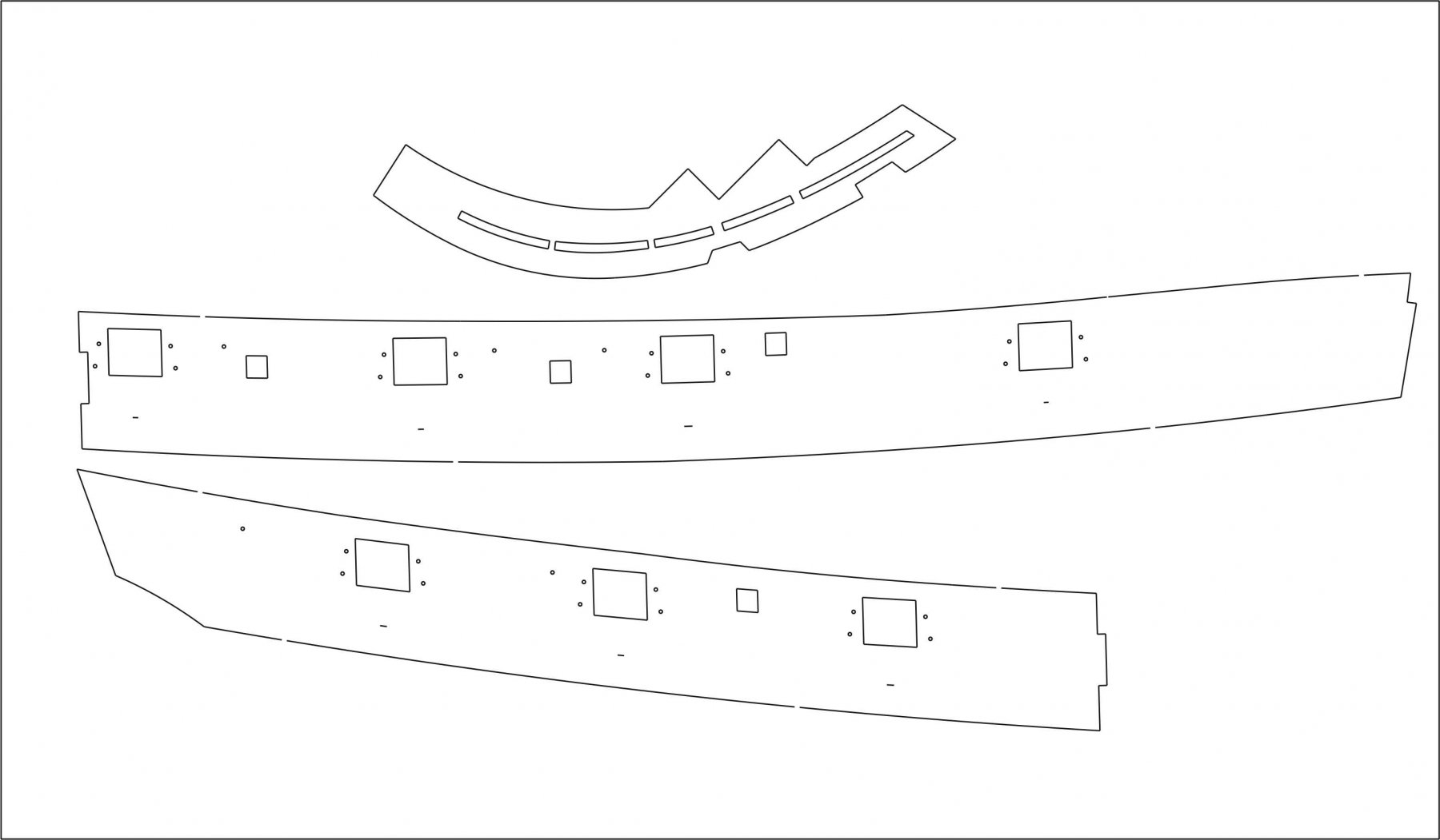
Right, Just reinstated the little lines denoting the upper edge of the main wale, and also added the location holes for the inner bulwark cleats on the gun port patterns. Also, added more tabs to the rabbet line on the prow. These are now the kit versions.
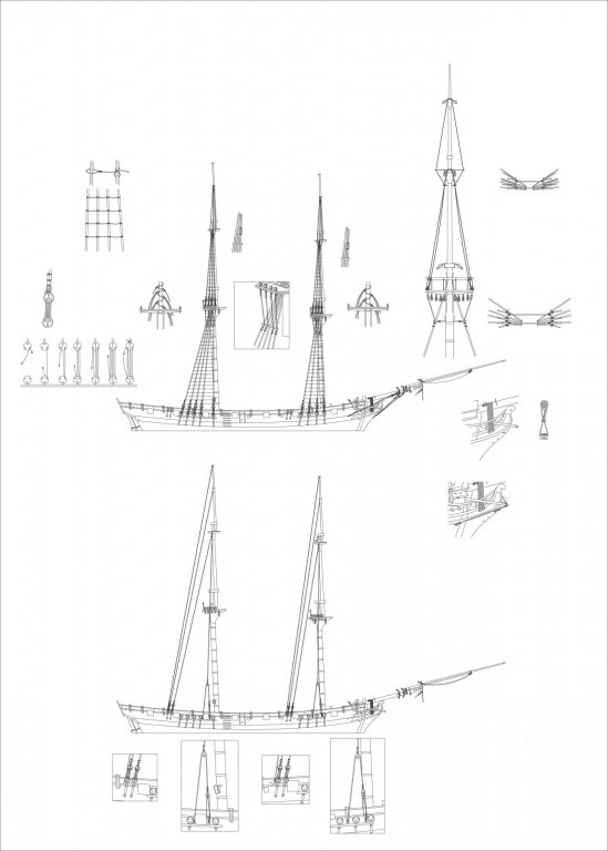
Also attached is one of the 6 50x70cm sheets for masts (already done), yards and rig, before being imported into Adobe InDesign for text and other stuff..
- flyer, Jim Rogers, Ryland Craze and 15 others
-
18
-
12 hours ago, Duncbe said:
This is really cool that we can see this process. I've been reading a lot of your posting and see that you have the laser cutting outsourced by a company, Don't feel brave enough to get your own?
Thanks! regarding a laser machine, I could get out a large loan and get one, along with the workshop space I would need to rent, as I am not sure I would be allowed to have one in my garage with the noise 24/7 in a residential area. Nothing to do with being brave, more to do with economics. I would rather invest my (little) money in stuff like decent materials, resin castings and nice printing. It may surprise you to learn that even some of the largest manufacturers sub contract their laser cut work, and as far as I know, due the chemical process, all photo etched parts are sub contracted.
10 hours ago, Malcolm Greig said:Excellent posts Chris, you really are an expert. I very much enjoy your posts and the comments of other followers. Your speed and volume of work is amazing.
Thank you, although I hesitate to be called expert, I see a lot of stunning work on these forums.
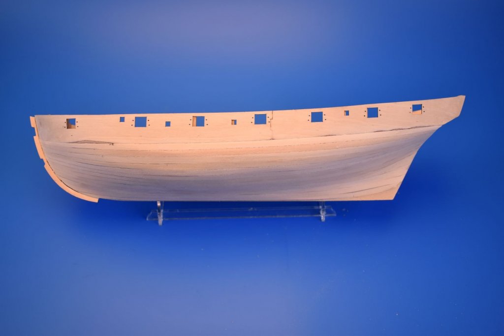
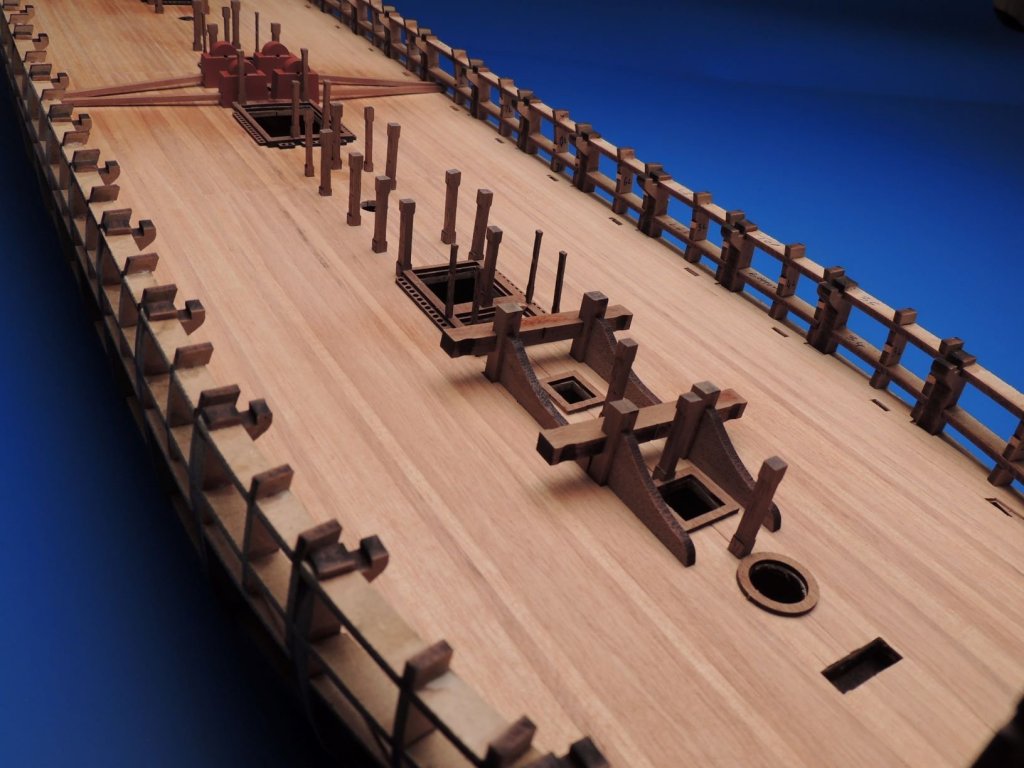
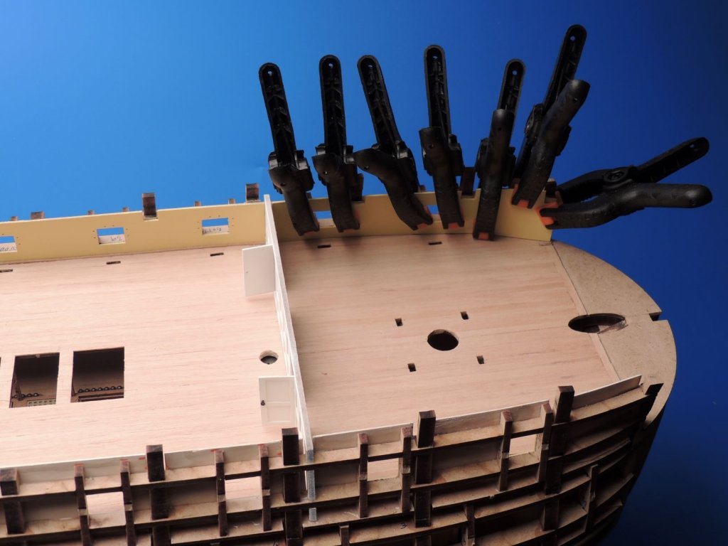
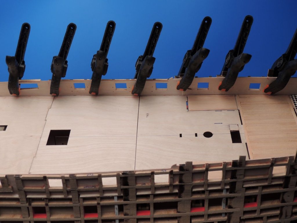
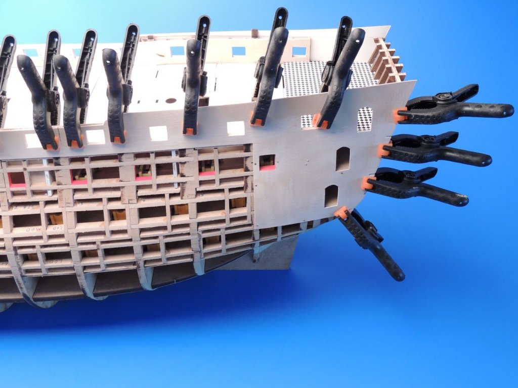
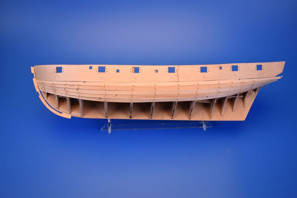
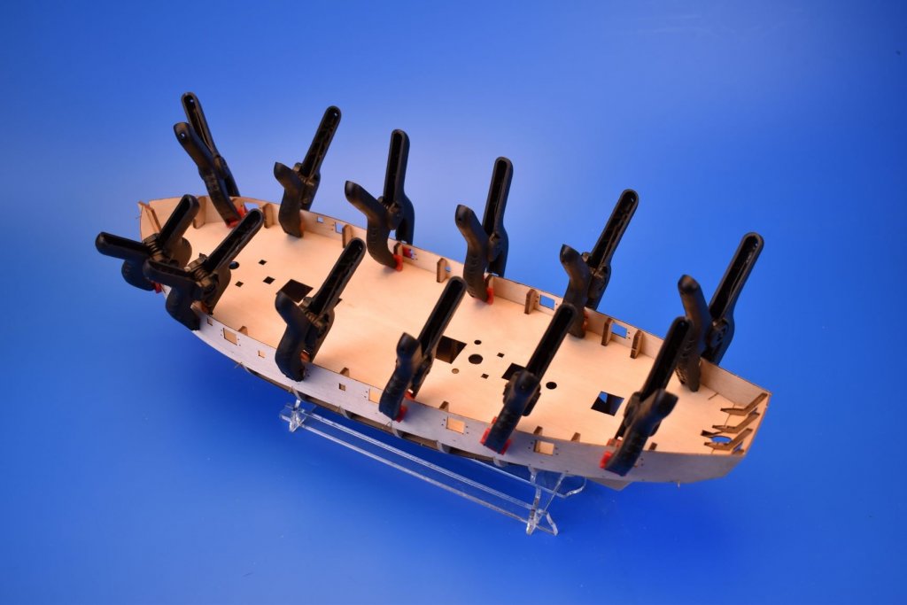
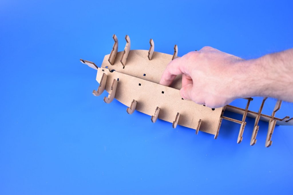
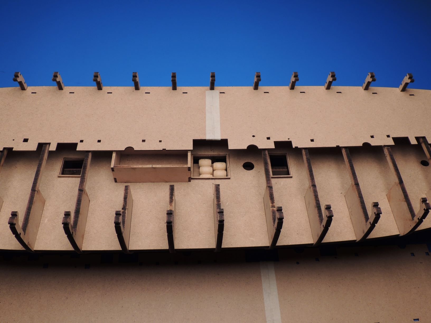
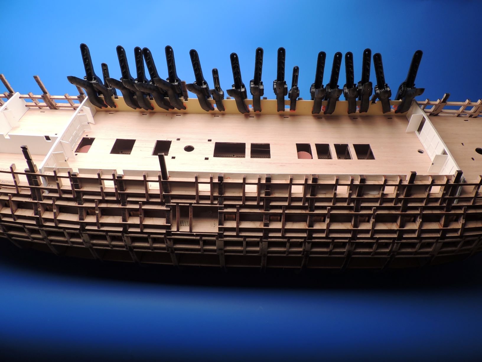
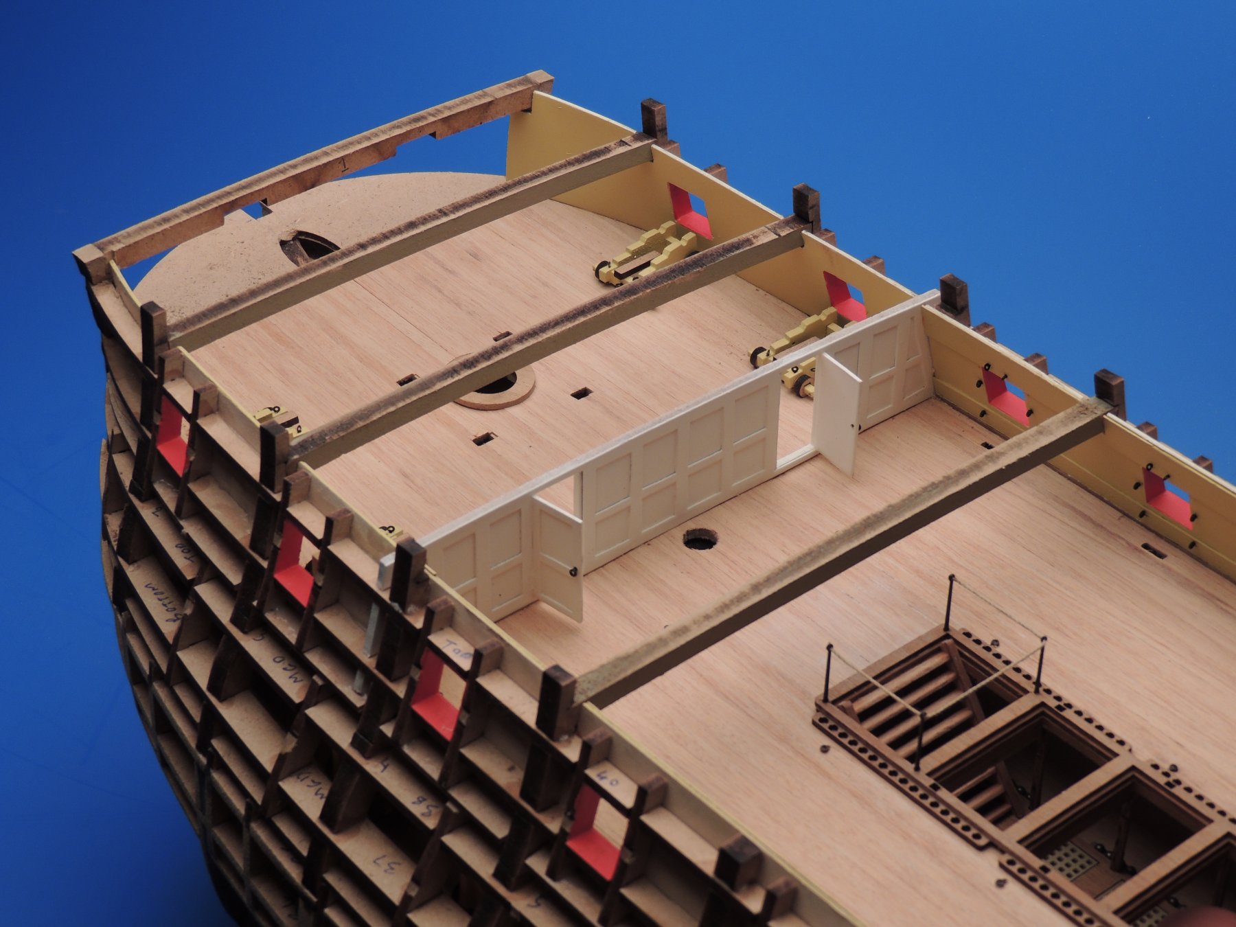
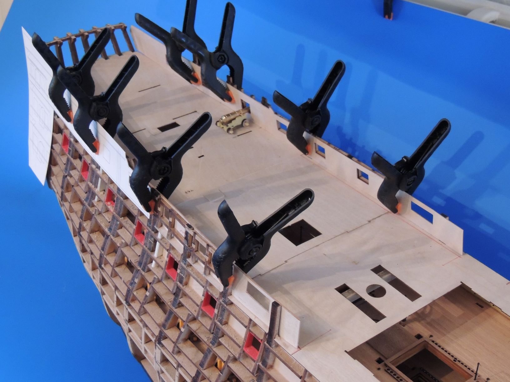
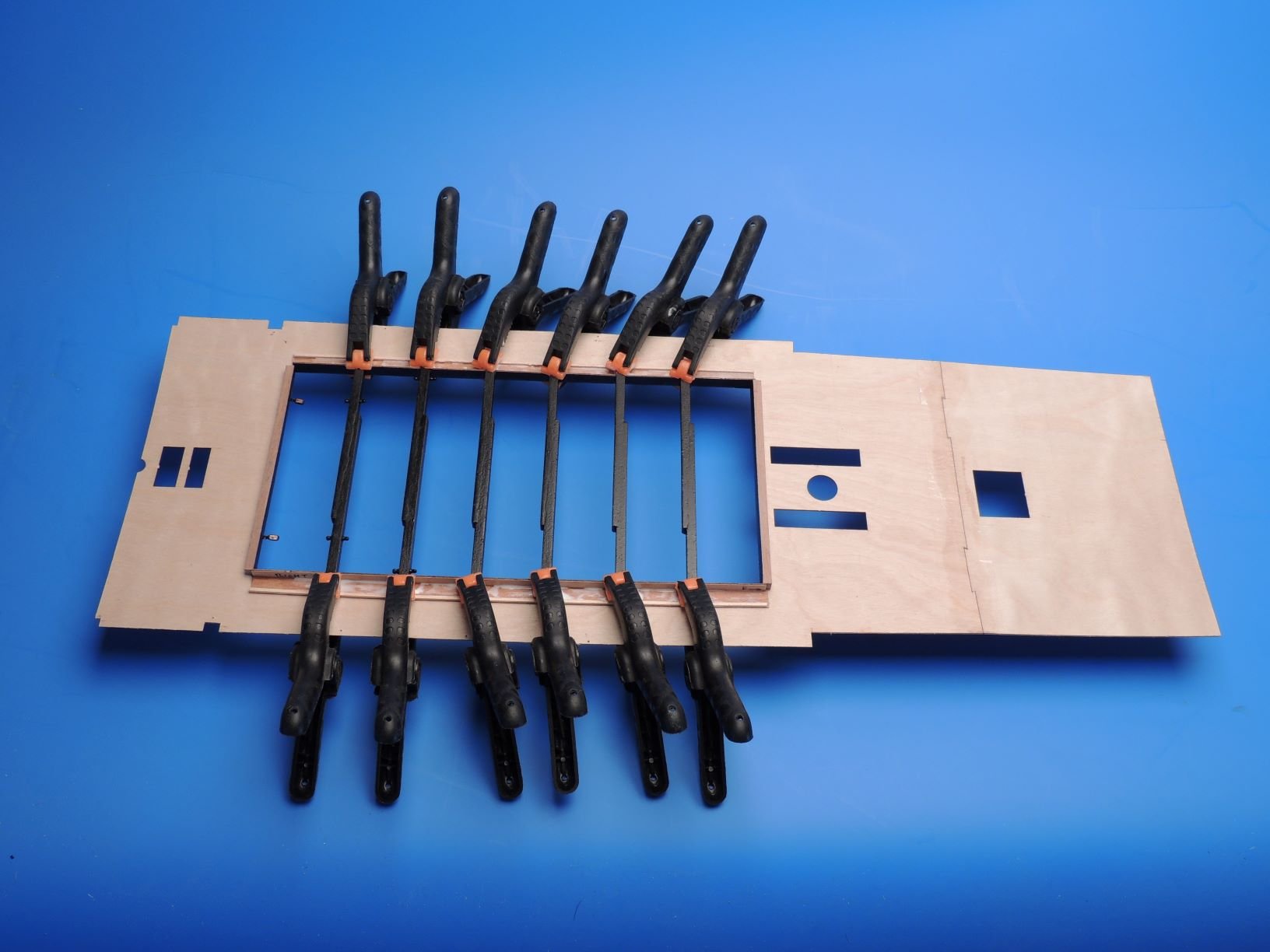
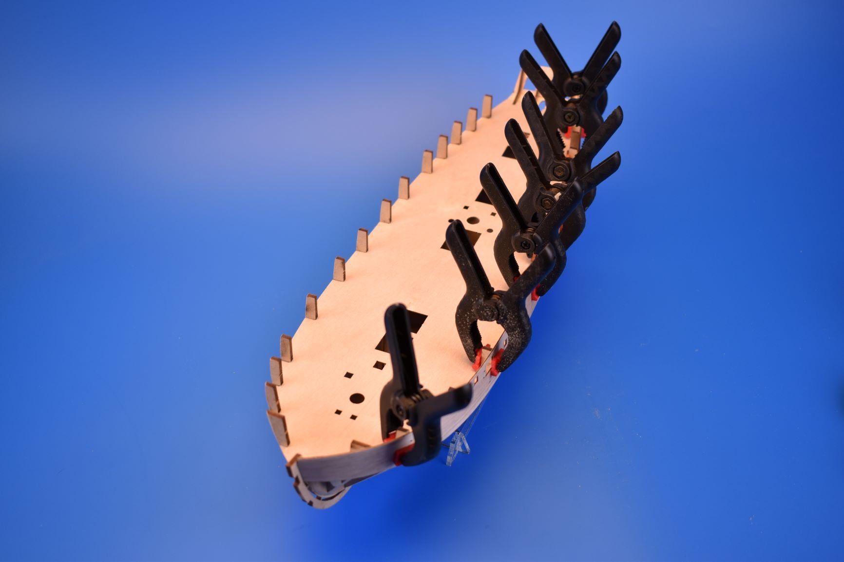
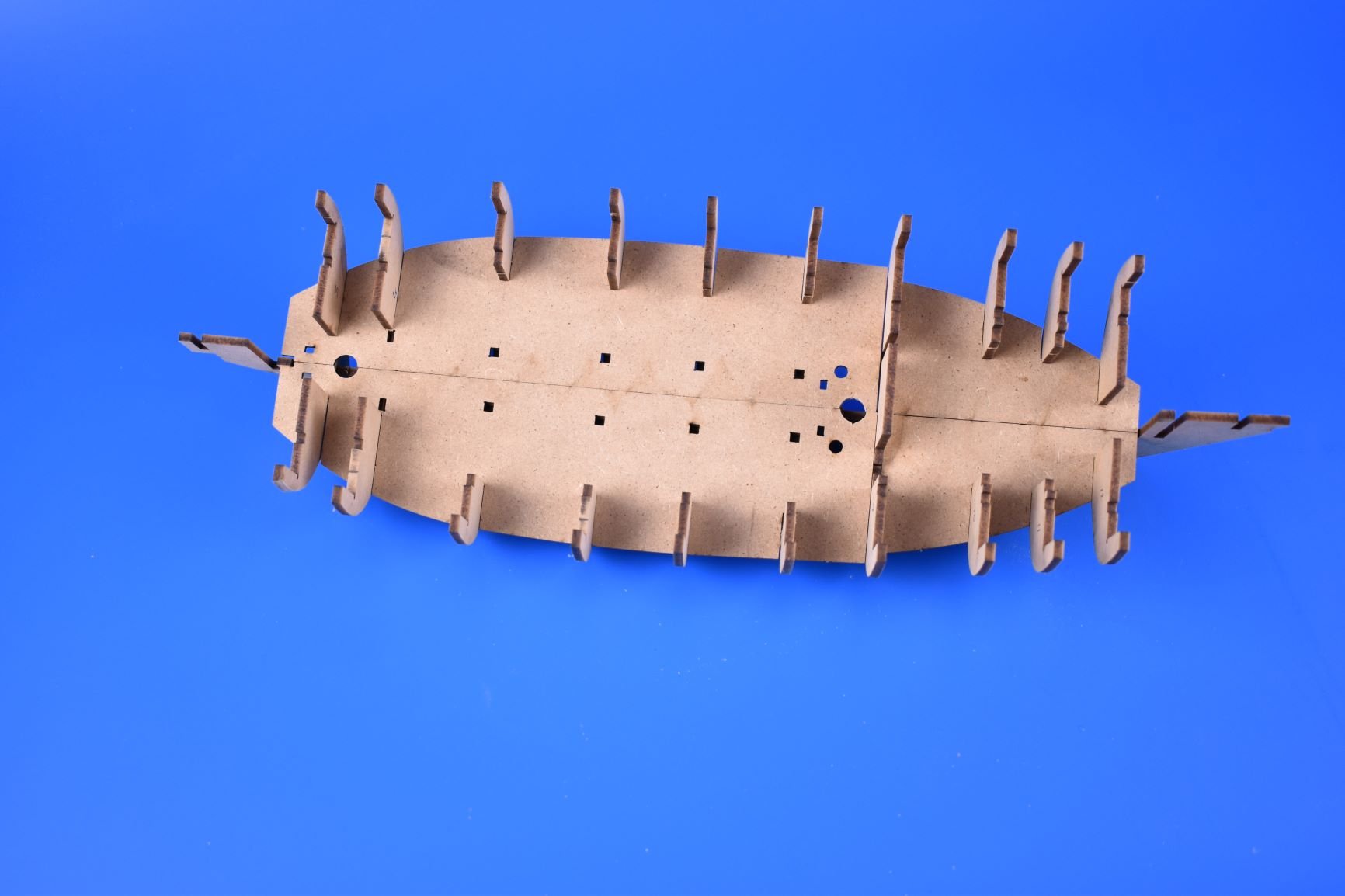
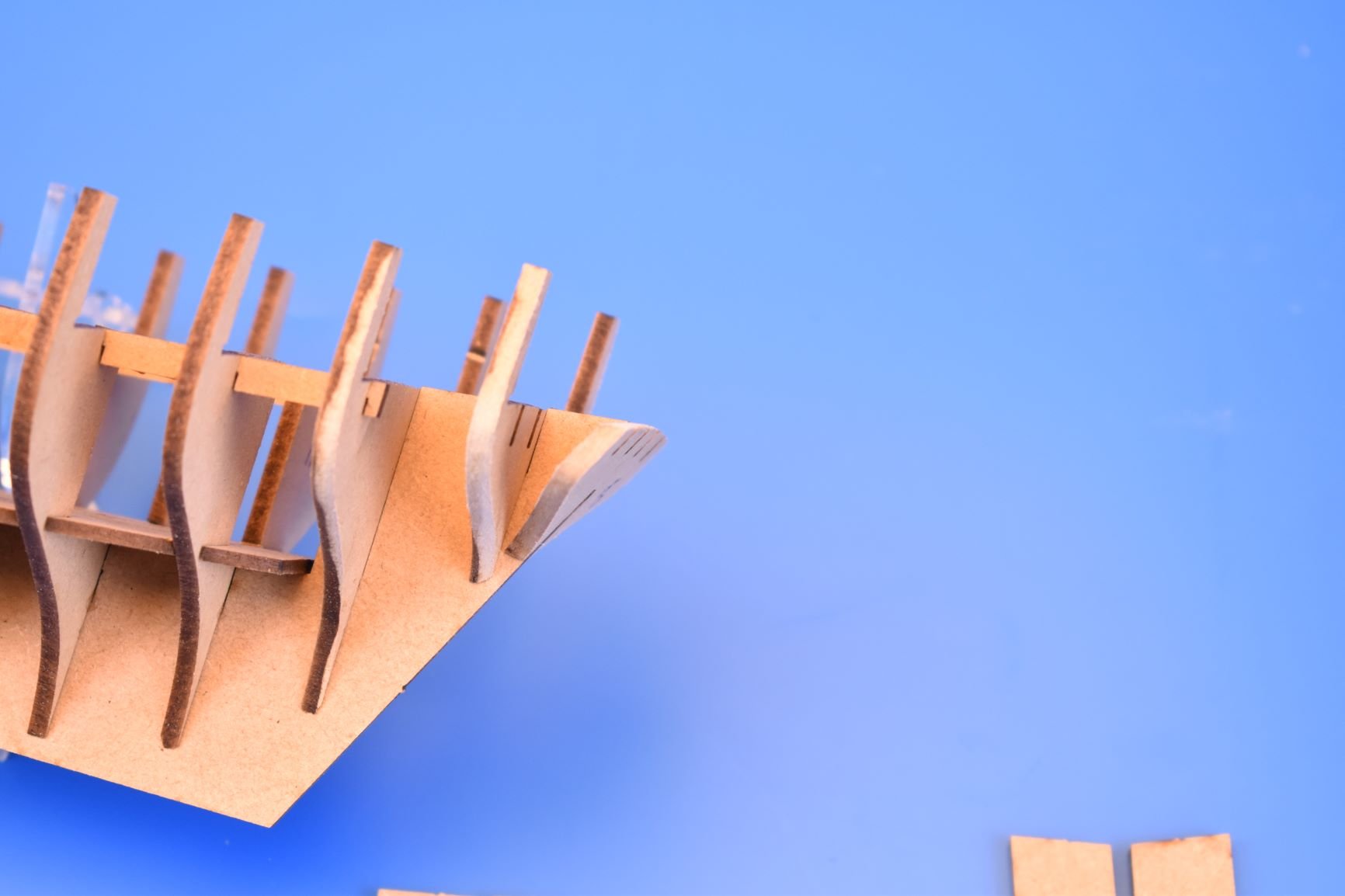
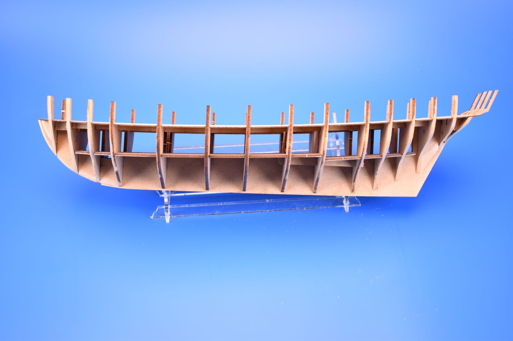
OK, this morning (got up very late..), I took off the clamps and pins holding the gun port patterns in place, the basic structure is now more than strong enough to take the planking, with the stern especially being a lot more protected than my first prototype. I think the only way to break any part now would be to drop it from a height onto a hard floor. It has taken a day's work to get to this stage, but perhaps 3 hours work, as most of the time was taken was waiting for the PVA glue to cure.
On the last photo, I added a series of small marks under each gun port. I have since deleted these, but I am wondering if I should reinstate them, as they are markers for the curve and height on the main wale, and where the second planking should start.
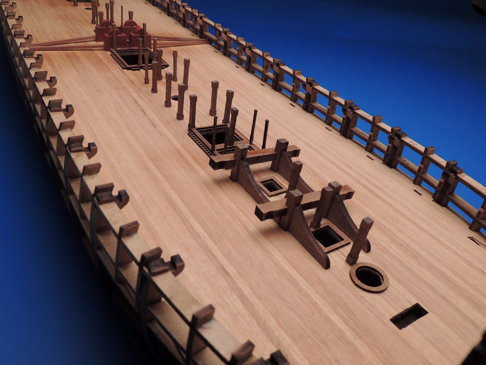
The last pics are from the first prototype, where I just slapped everything together to check that everything aligned as it should and the various openings for bitts and masts were fine. If you look at the stern frames, they come further down the deck than the second prototype, I thought they were too obtrusive, so shortened them as much as I dared without compromised structural integrity.
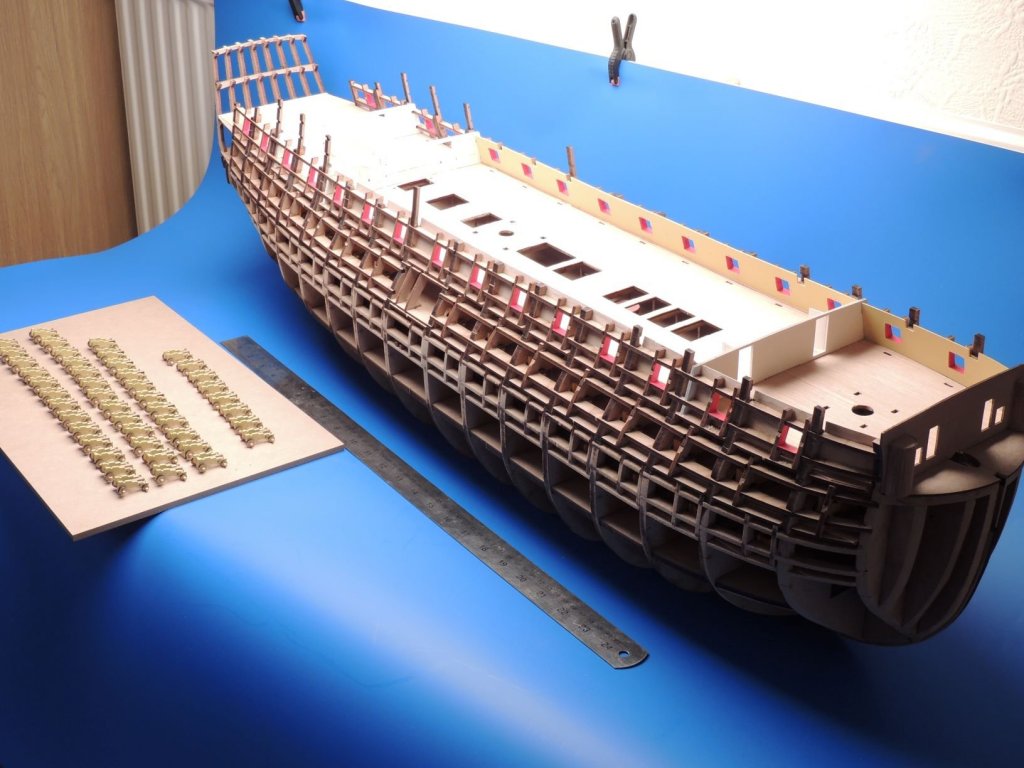
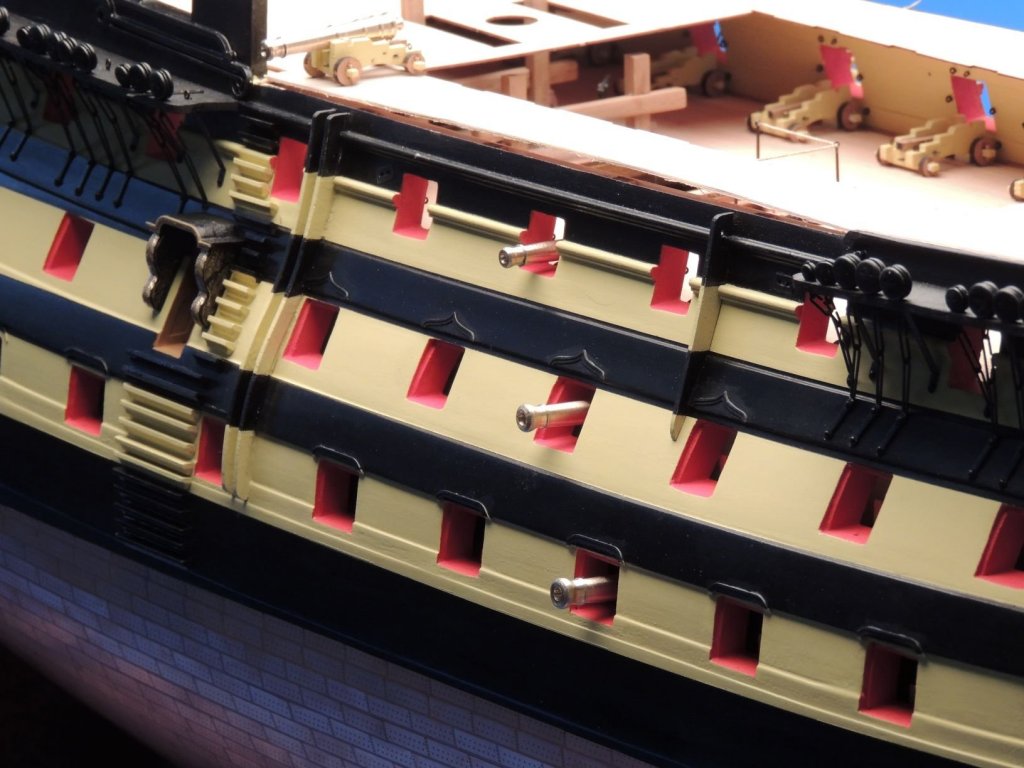
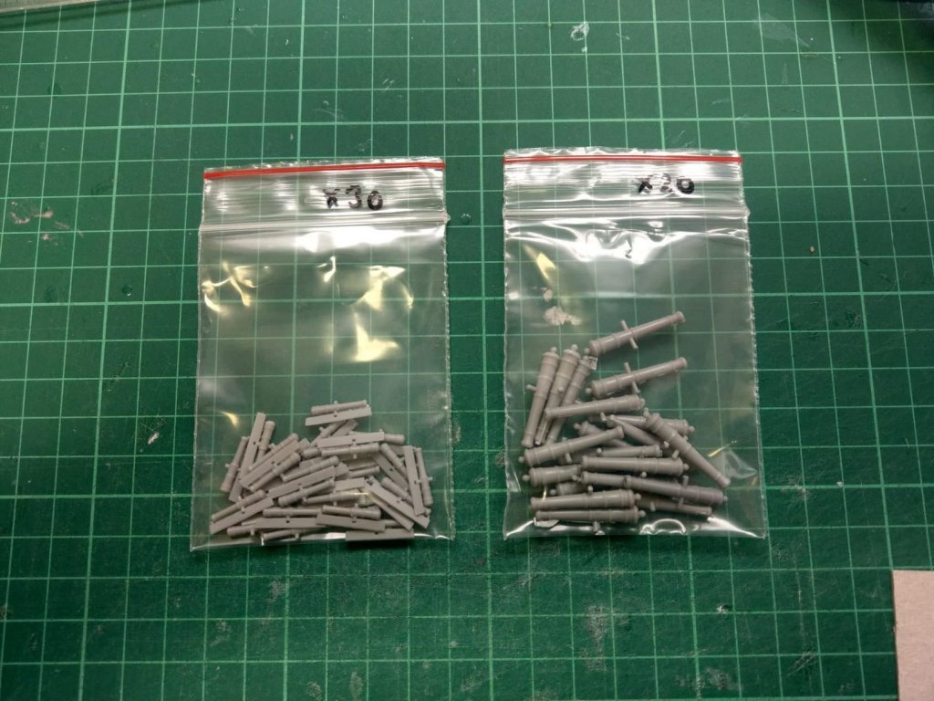
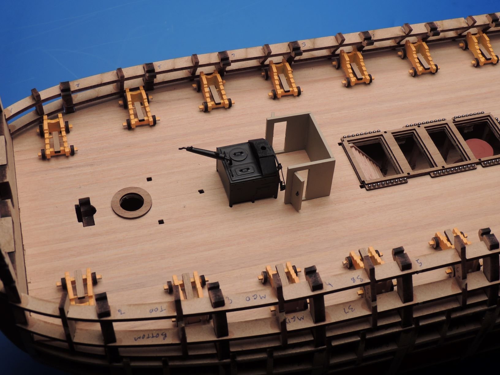
Also, I have the cast resin cannon ready for the prototype model, the 4 pounder and half pounder. The first 50 kits will be this colour, but after this they will be cast in black resin (why didn't I ask for black resin to begin with, dammit)!


- Chuck, Haliburton, DelF and 19 others
-
22
-
Cheers!
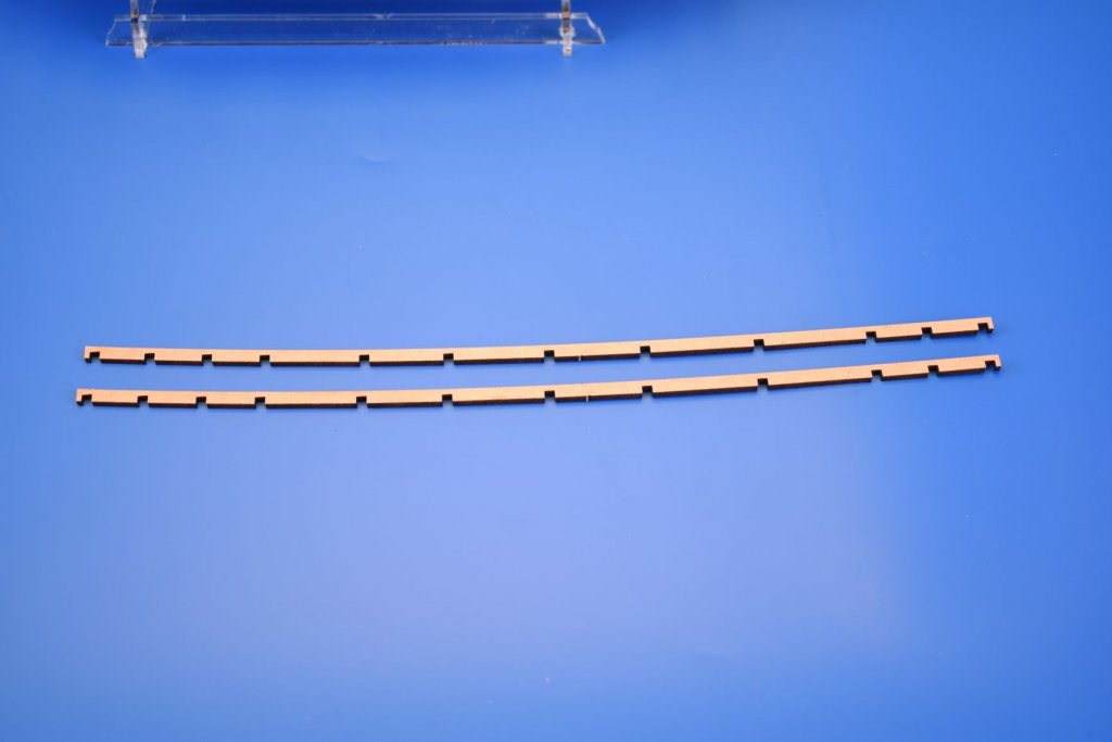
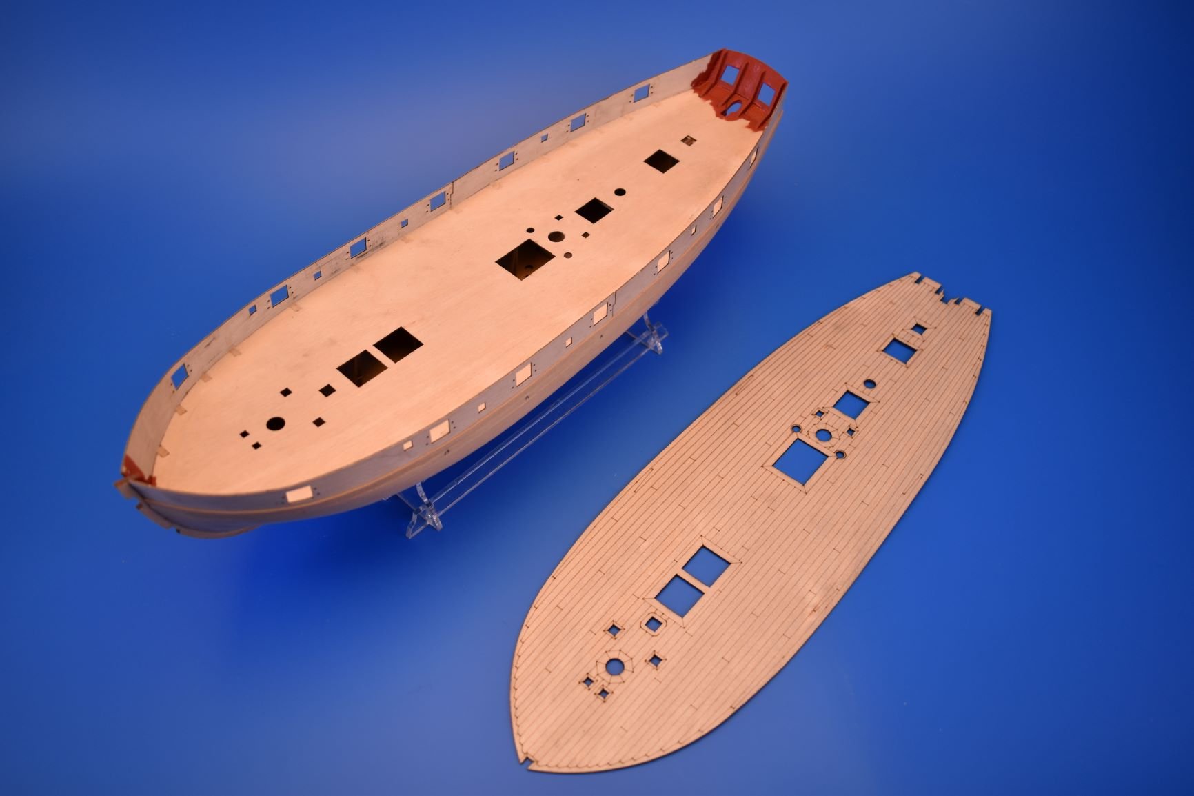
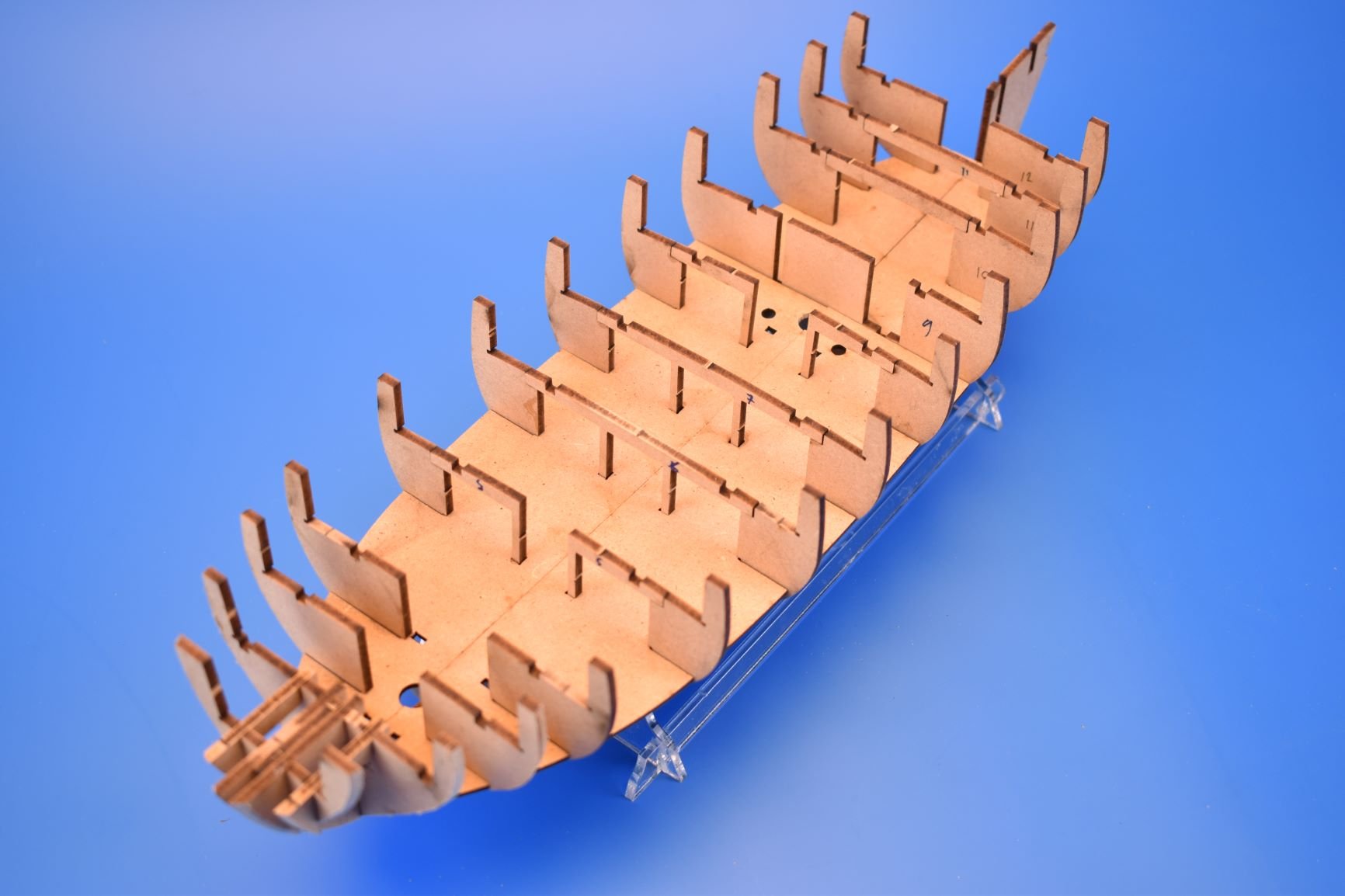
Looking at the nice clear stand, I think it will get scratched/marked too much whilst in the building process. To remedy this, I have just added a slightly simpler cradle to one of the 3mm MDF sheets, so the modeller can use this when building, and then change the stand for the clear acetate version when all done.
ETA - Ply gun port patterns have been clamped, pinned and glued in place, so will have to leave it until tomorrow now..
-
1 minute ago, vossy said:
Hi Chris, did you design the Caldercraft 1:72 Victory? If so, how does it compare in accuracy/detail to your much anticipated Amati 1:64 version?
Cheers
Chris
I designed the majority before I handed in my notice in late 2001. I had nothing to do with the stern carvings or PE. I left before completing it.
I cannot comment on the differences, as there are quite a few years to separate the two, and it would not be cricket to talk about accuracy/detail between the two.
-
On 7/4/2019 at 3:12 AM, Jib said:
So after many years thinking about building a victory kit, I set out to discover which is the definitive one, I come across a posting regarding one in development that is anticipated to be the new premier, after reading more into it decide, yep that's the one for me, and then find myself here only to discover the designer, is a fellow forester! How cool is that.
You must be close, then, I am in Cinderford!
-
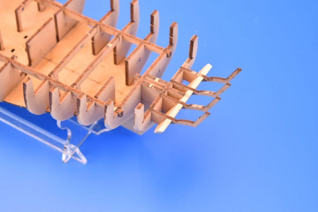
As this is quite a small model, the topmast cross trees would very fragile in wood, even ply once the hole has been laser cut. If it was to be cut in wood, the cross trees would have had to be drawn too over sized. To remedy this, they are now in photo etched brass form, and much stronger to take the topgallant shrouds.
There is a problem with the jibboom rest though (left of the picture), which needs to be sorted..
- BenD, Mike Y, GrandpaPhil and 18 others
-
21
-
I kept the cannon tackle eyebolt holes in the patterns as drilling them out before fully planking the outer hull works fine. Wonder if I should add the location holes for the inner bulwark cleats?
- paulsutcliffe, GuntherMT, druxey and 13 others
-
16
-
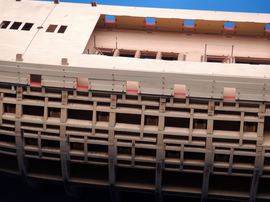
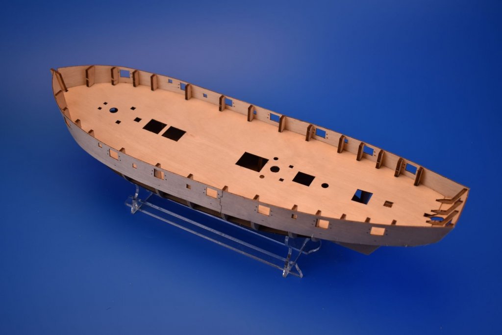
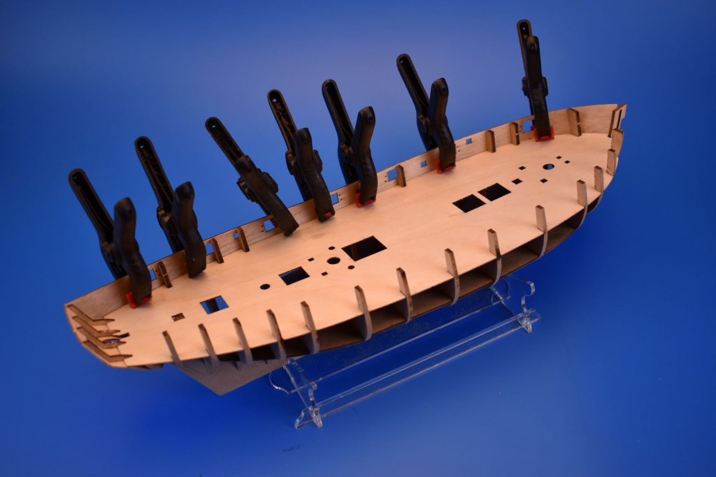
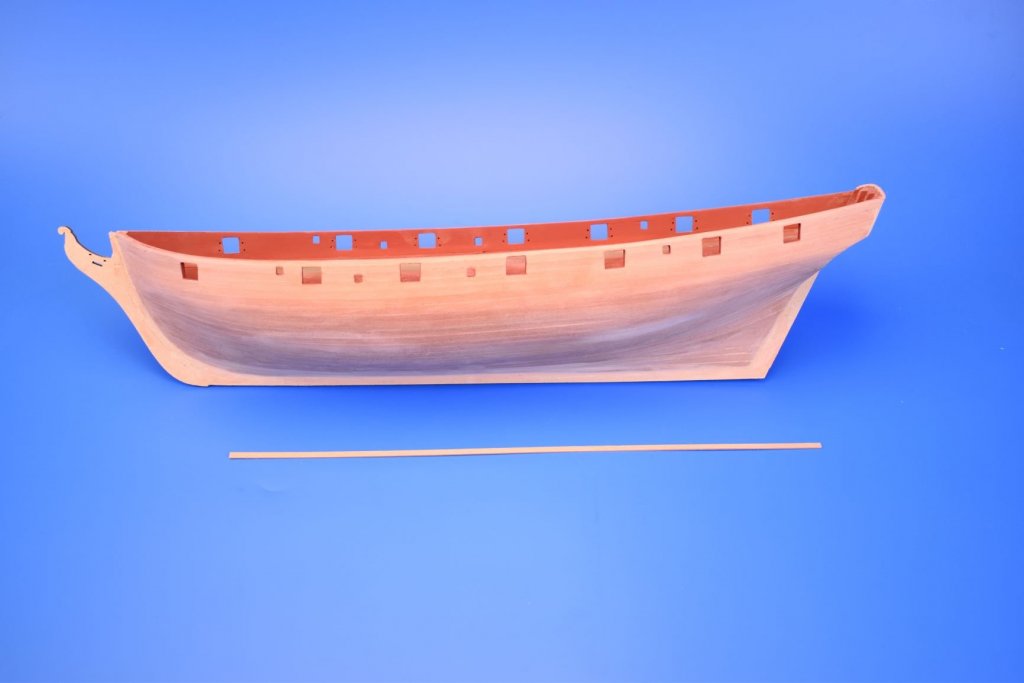
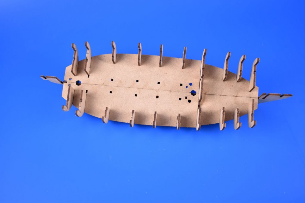
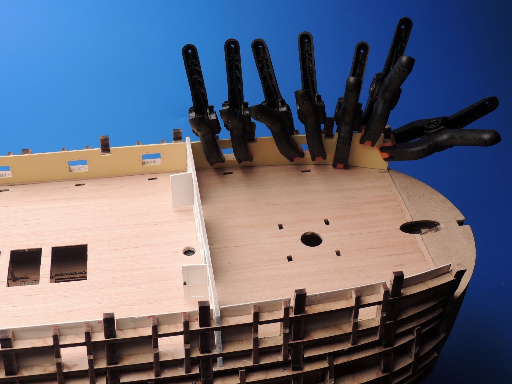
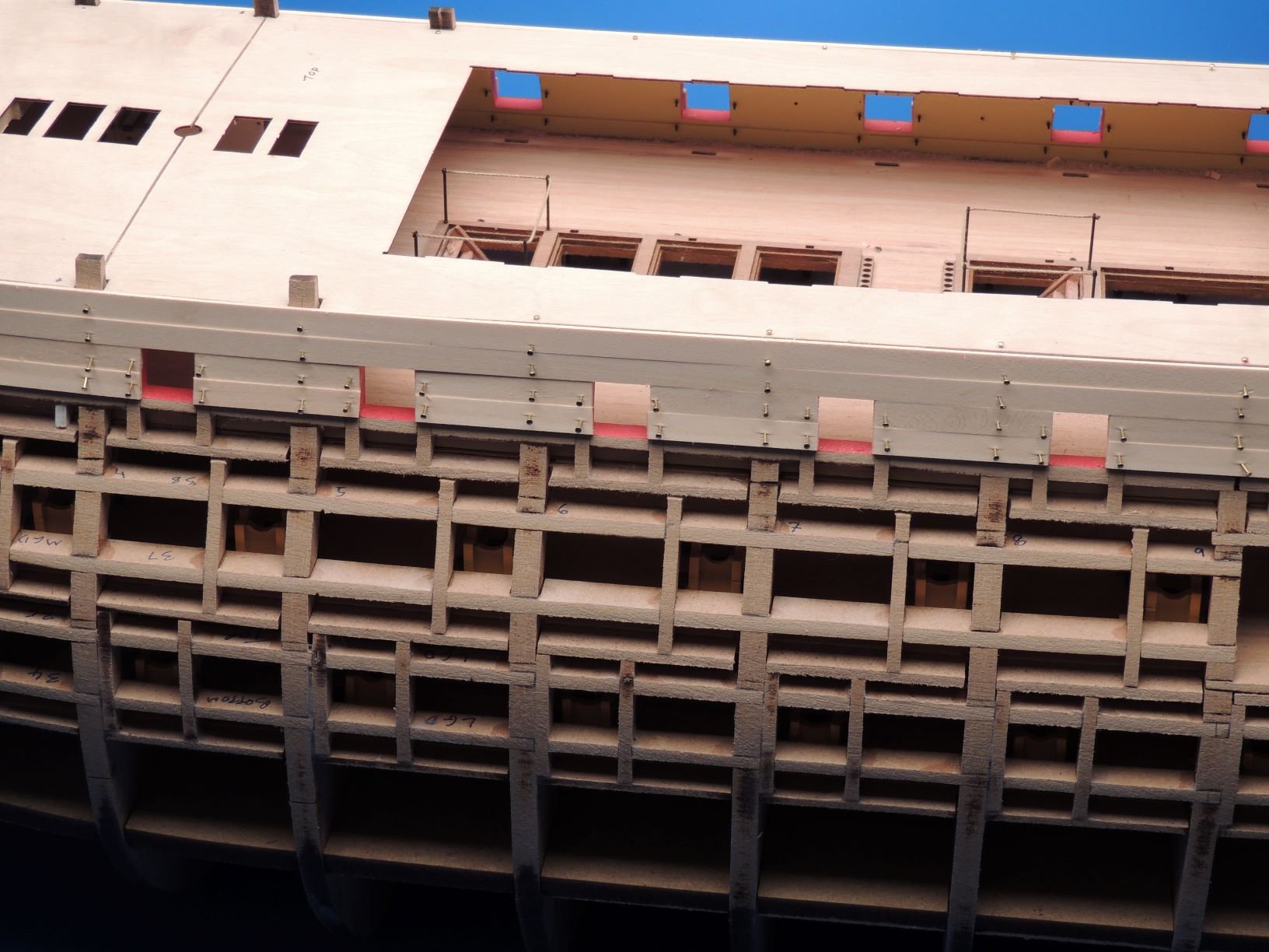
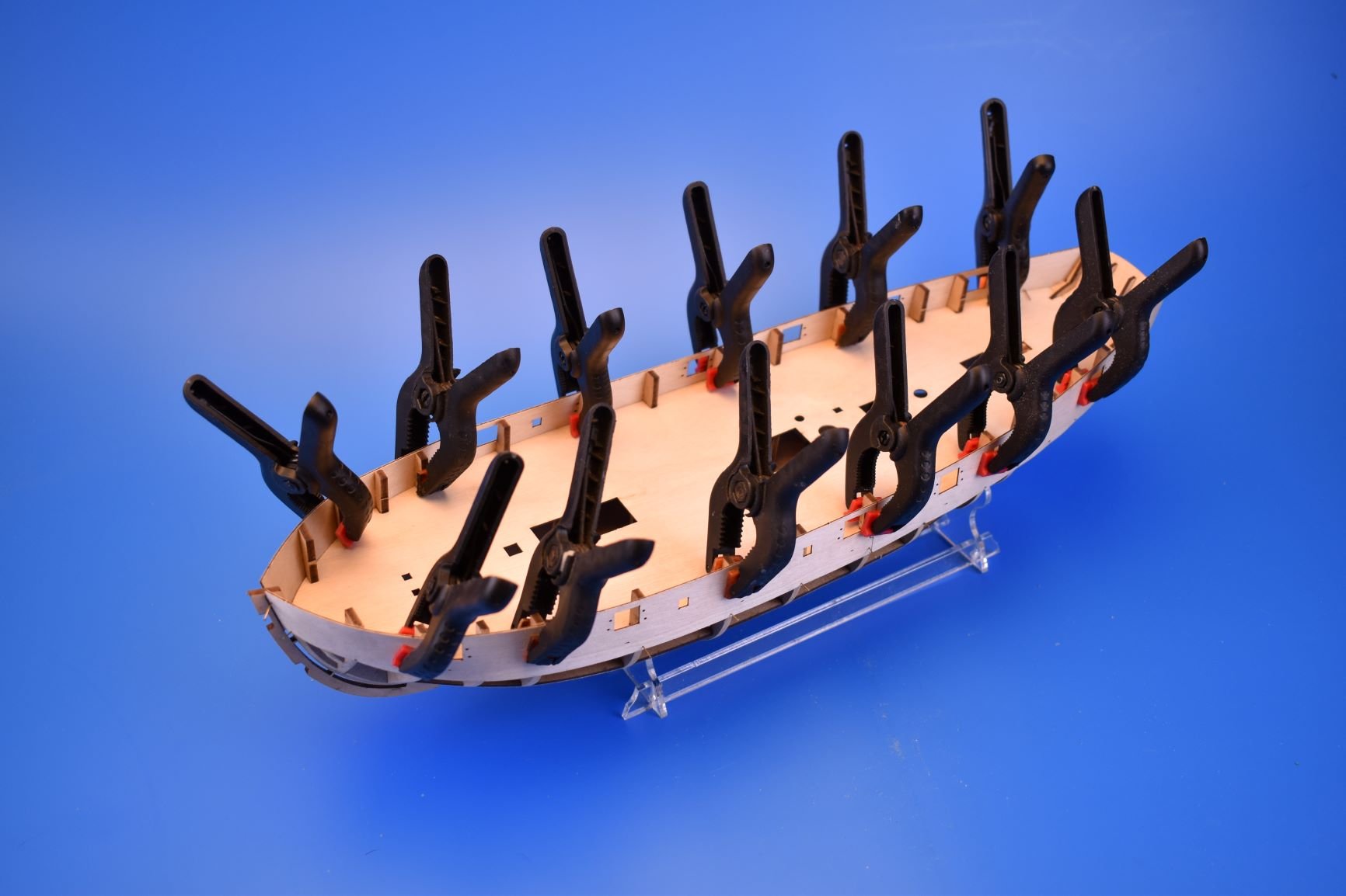
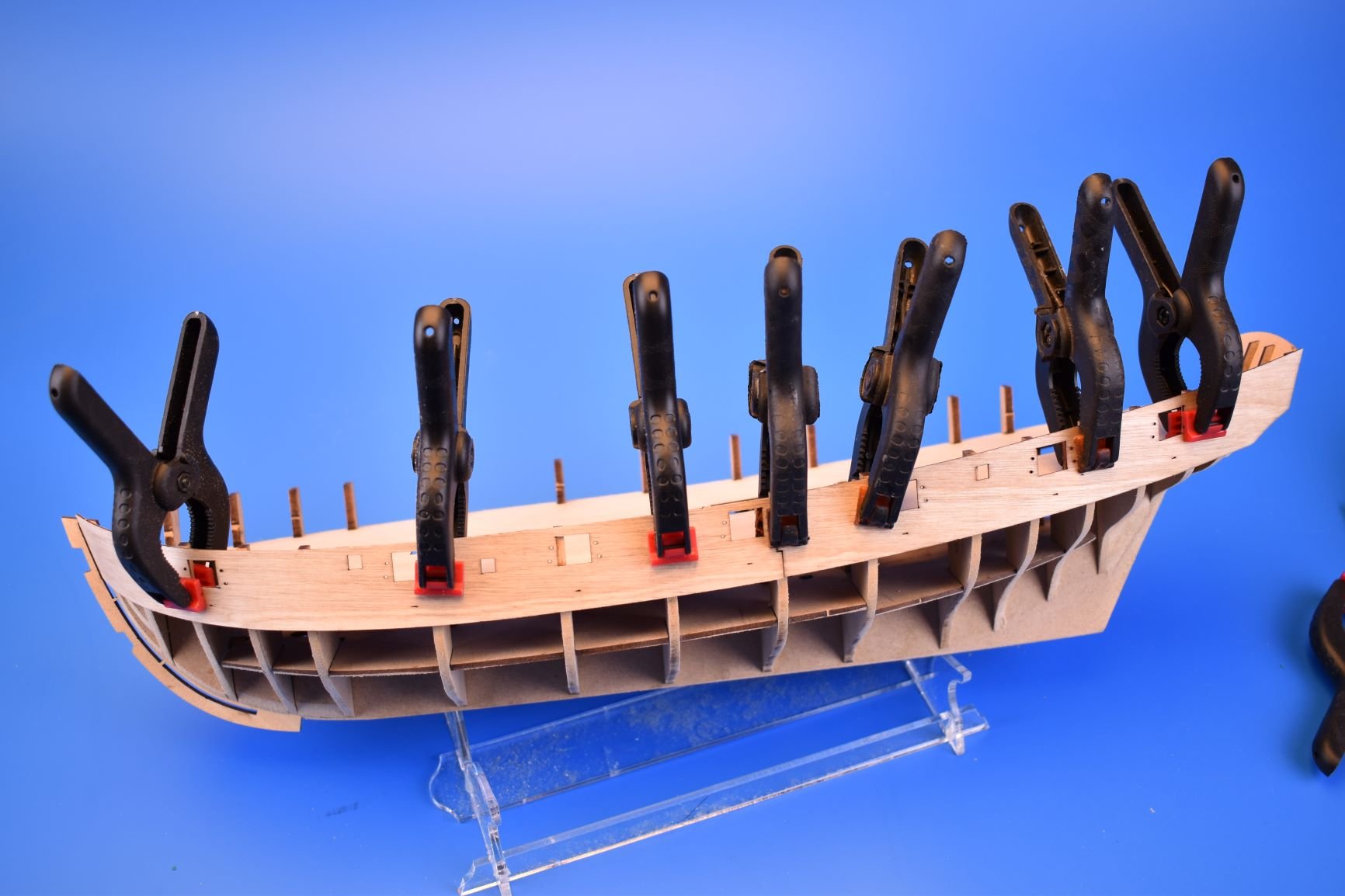
Right, just gave the 0.8mm ply gunport patterns a good soak and just clamped one side into position without glue to check fit. Looks fine, less than a mm to tale off at the stern.
Once both sides are securely glued in place, the structure should be a pretty solid base on which to start the planking, and due to the amount of bulkheads, the sleek hull form should also be perfectly kept.


- coxswain, mtaylor, KARAVOKIRIS and 10 others
-
13
-
9 minutes ago, Gregory said:
Just a thought Chris, you might consider a built up stem of 2 or more pieces where you can get the grain to follow the long axis as much as possible.
You are way ahead of me in doing this sort of thing, but I am just learning with a laser cutter, and experimenting with fabricating some embellishments to one or more of the kits I am working on.
One of them is the Corel Resolution kit, that comes with the typical veneer stem, keel and stern..
I orient my pieces to align with the grain of the stock I'm using.

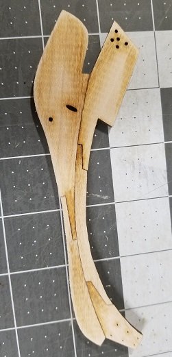
Still in the early prototype stage for me, but I hope to improve as I go along..
Thanks. I did actually do something similar with the Amati Fifie model I did a decade ago, but this could be done as the keel was all one part. I did think about making the stem from 3x1mm wood parts, but the variations in thicknesses may be too much over time, plus expecting all modellers to align three almost identical parts up perfectly (full pattern in middle with outer patterns 1.5mm shorter at hull edge) is maybe a big ask. The chances of the part being glued in a position that is slightly off angle are higher, which would be accentuated by the prow pattern when this is glued after planking is complete. I wanted the outer prow to be separate as I know how vulnerable this 3mm thick part can be when planking and sanding - but at the same time, a stable basis for the front planking, which is always a slight issue.
-
34 minutes ago, druxey said:
Some interesting design details there, Chris.
Thanks! Just a continuation of where I was heading when designing for Amati. Although I am still unsure about the slot in the stem pattern, I am wondering if it will cause more headache for modellers down the line with complaints about them splitting. The upside of it is the fact the planking at the bow follows the same line as that on the original plans. But I shall see how I get on when adding the ply gun port patterns. I want people to enjoy the building experience, not be frustrated with it.
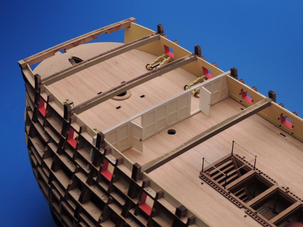
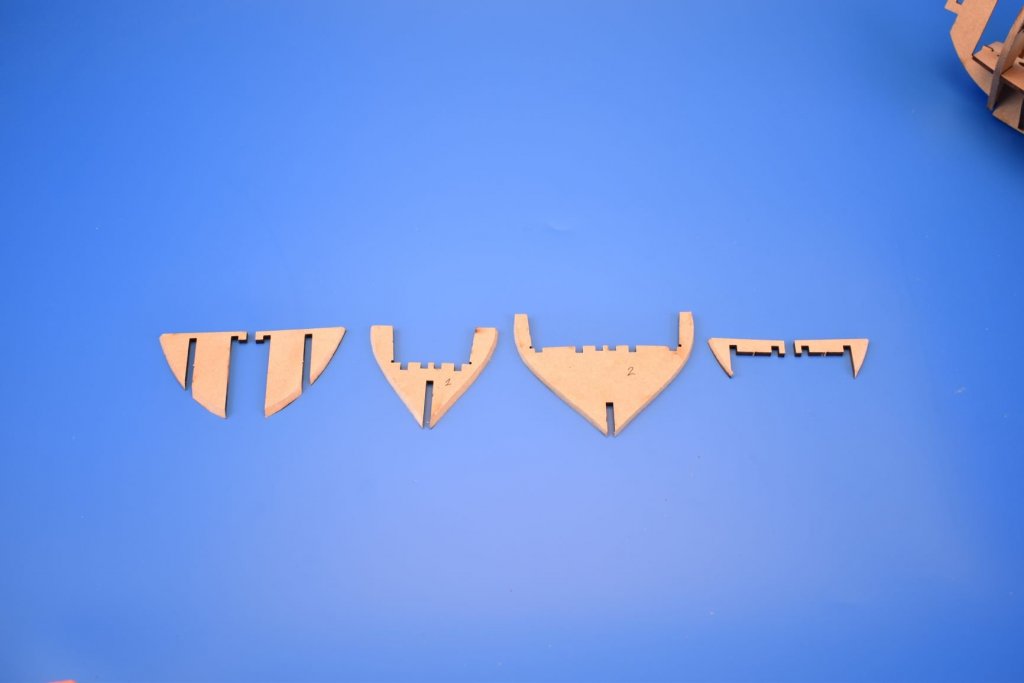
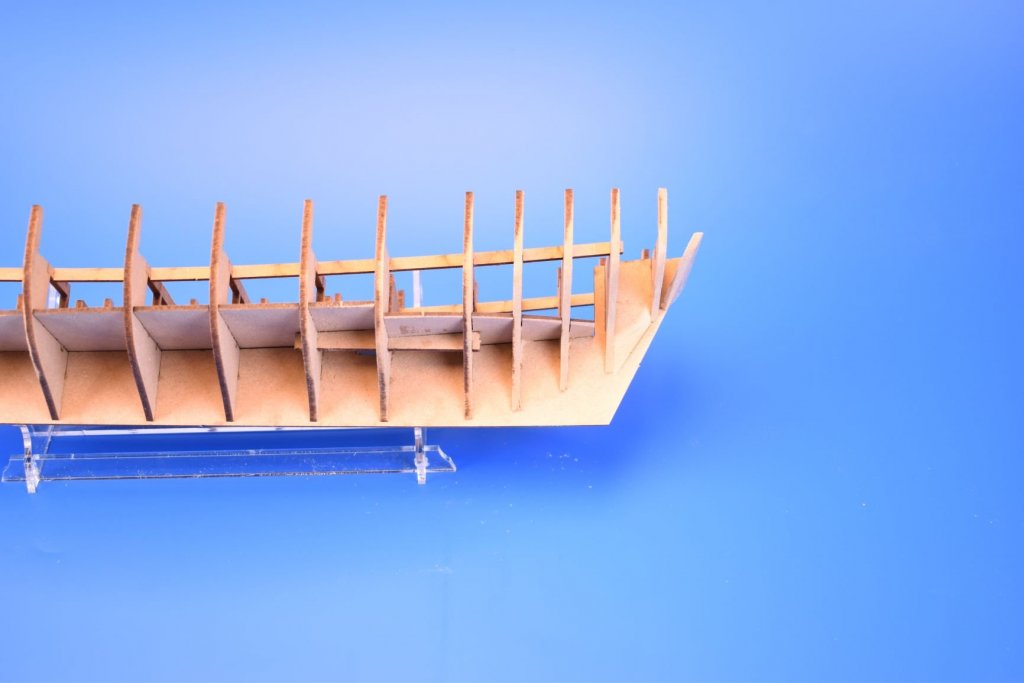
The only things I changed from the first prototype parts are the stern frames and order of fixing the upper stern board/transom, and the addition of a door opening on the 9th bulkhead, in case anyone wants to detail the lower decks.
-
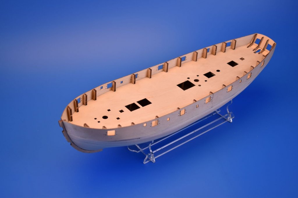
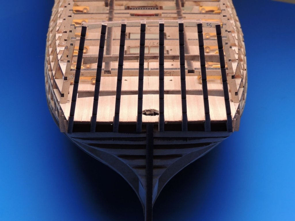
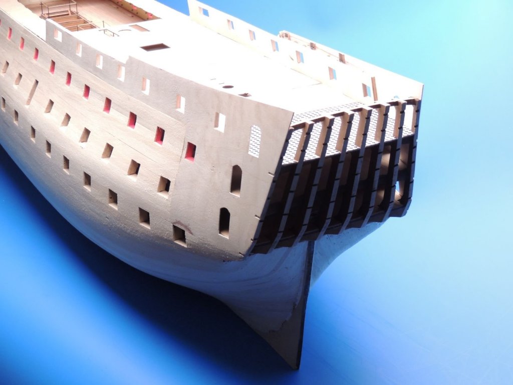
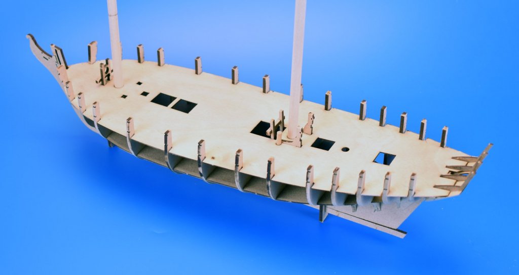
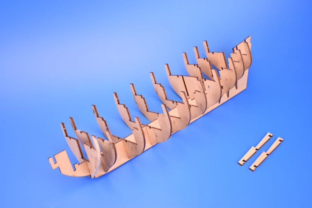
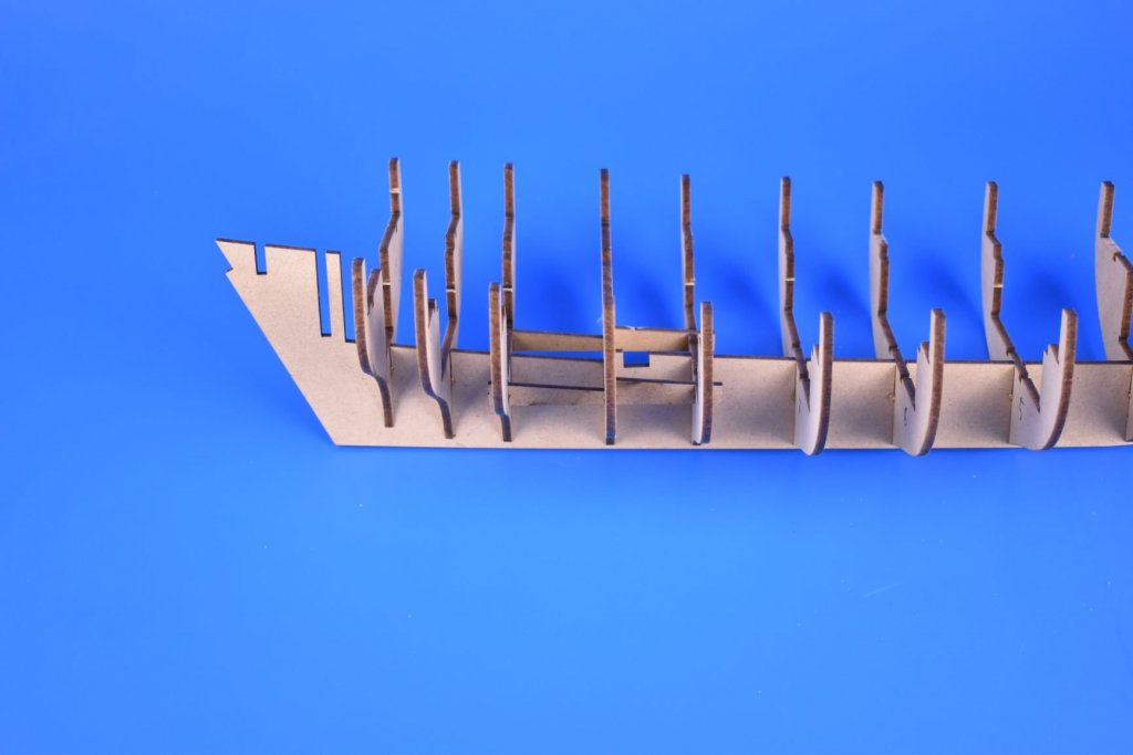
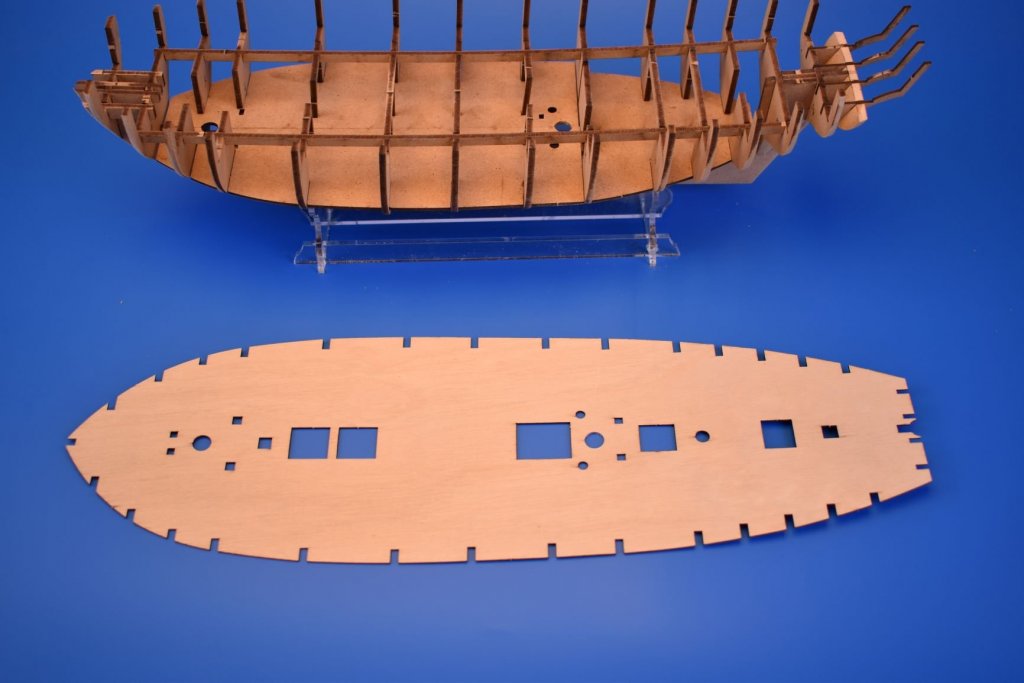
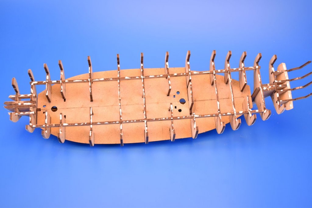
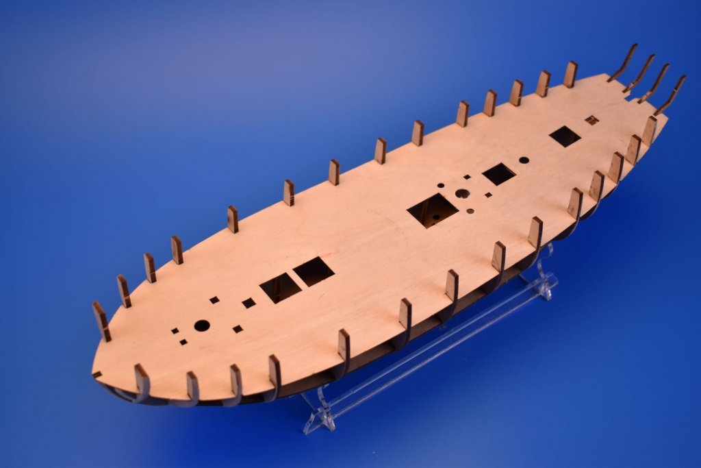
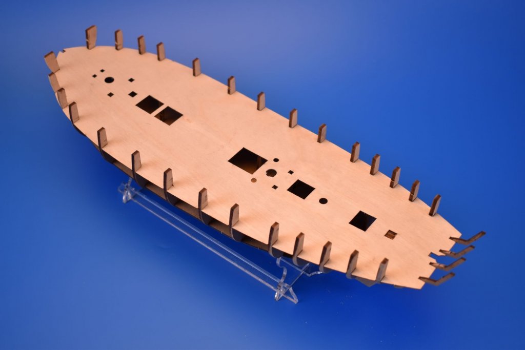
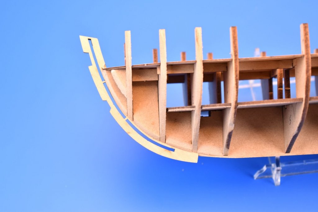
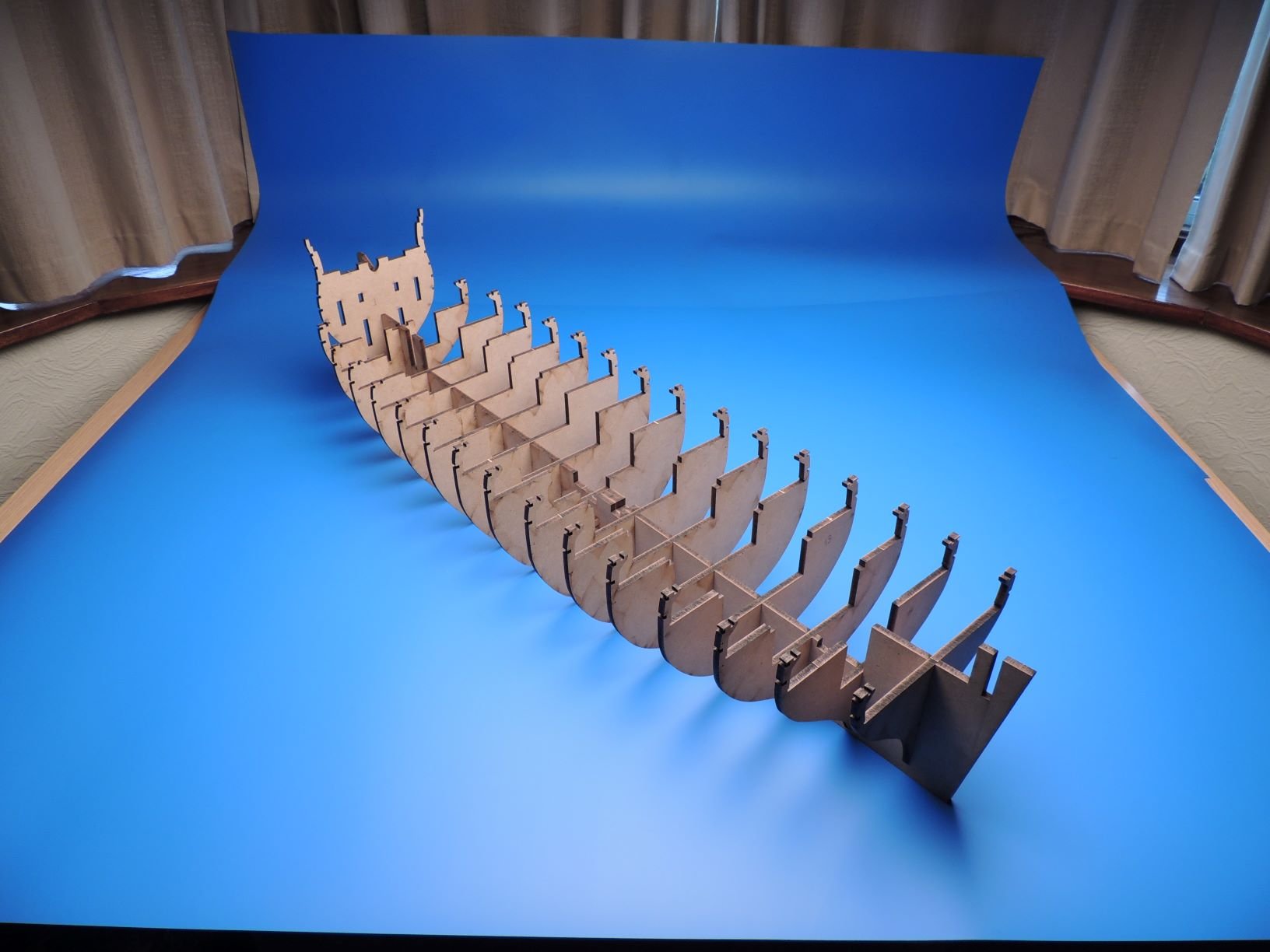
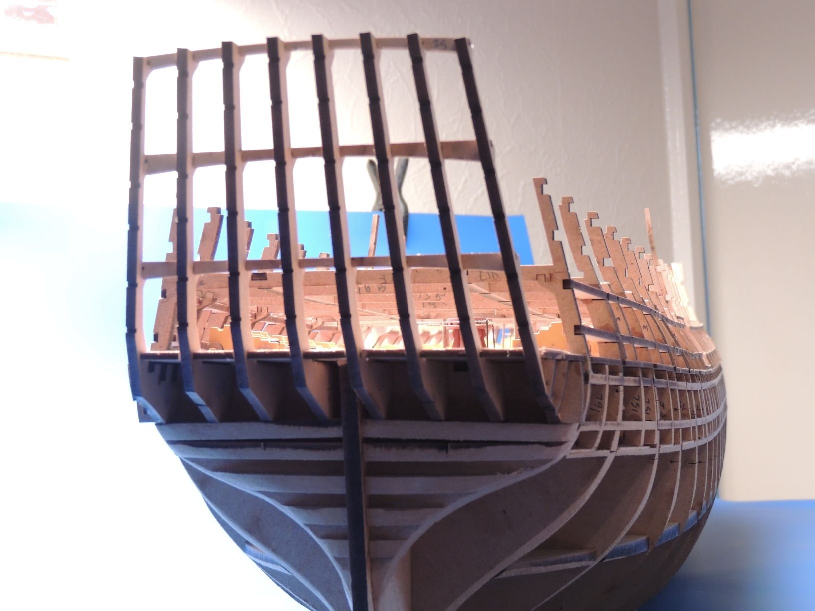
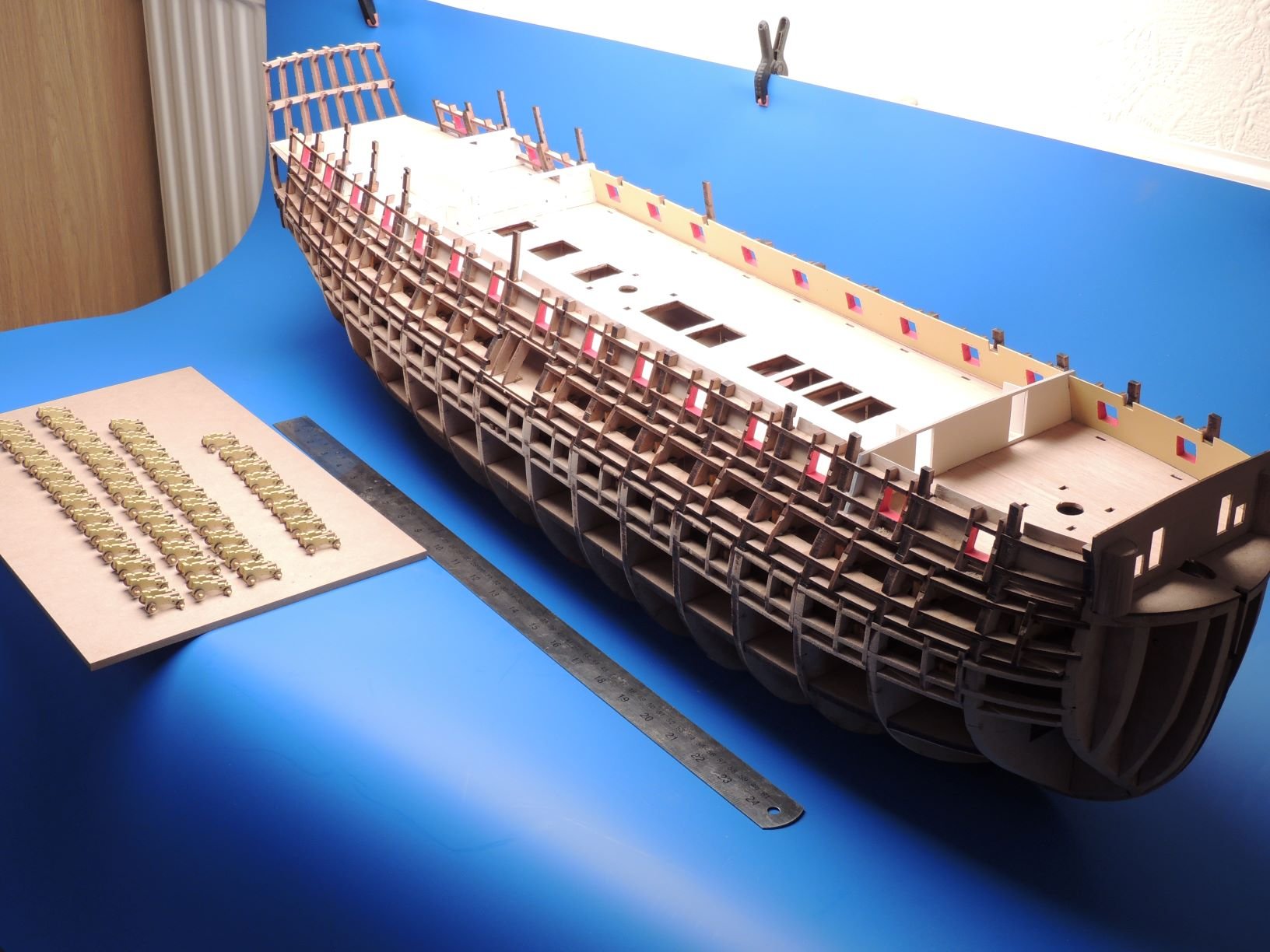
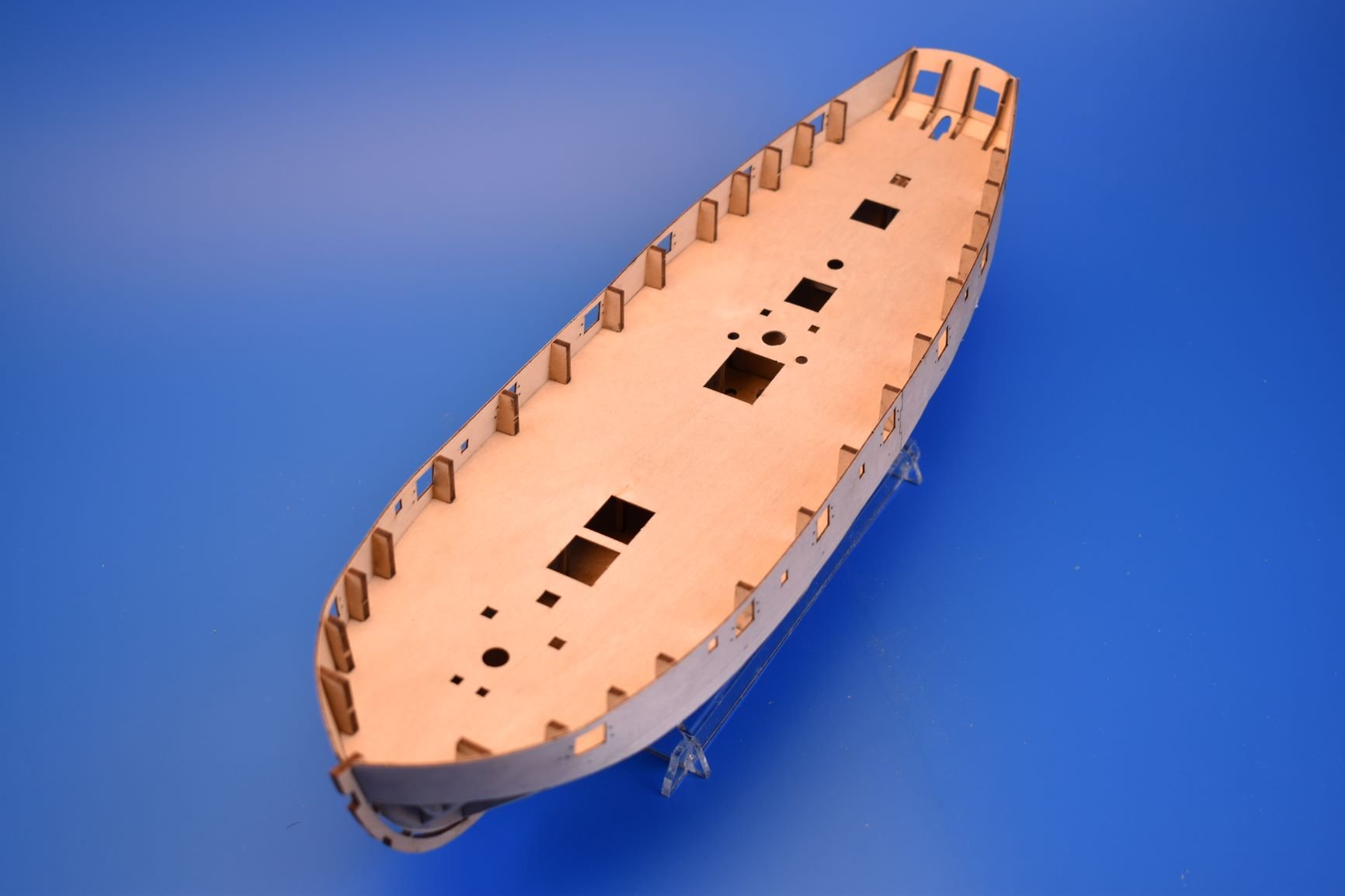
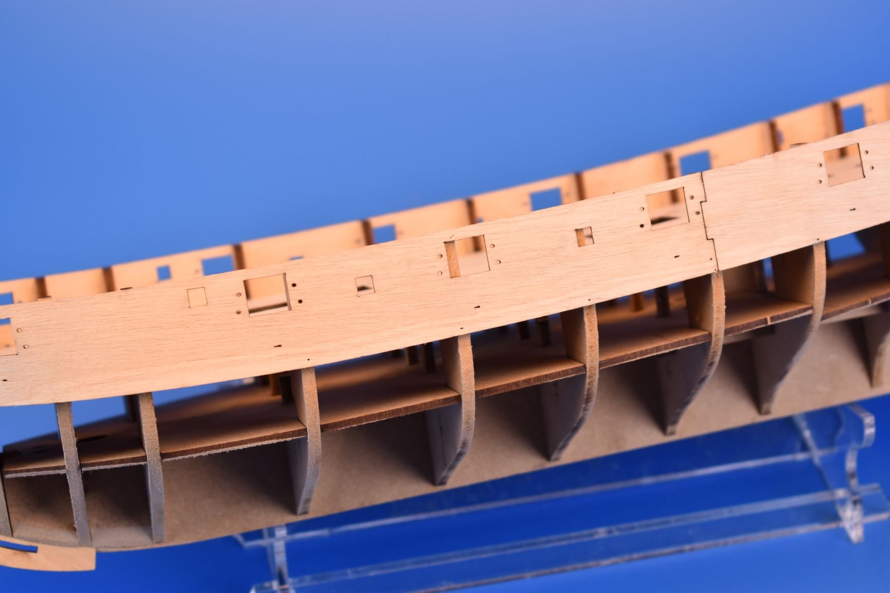
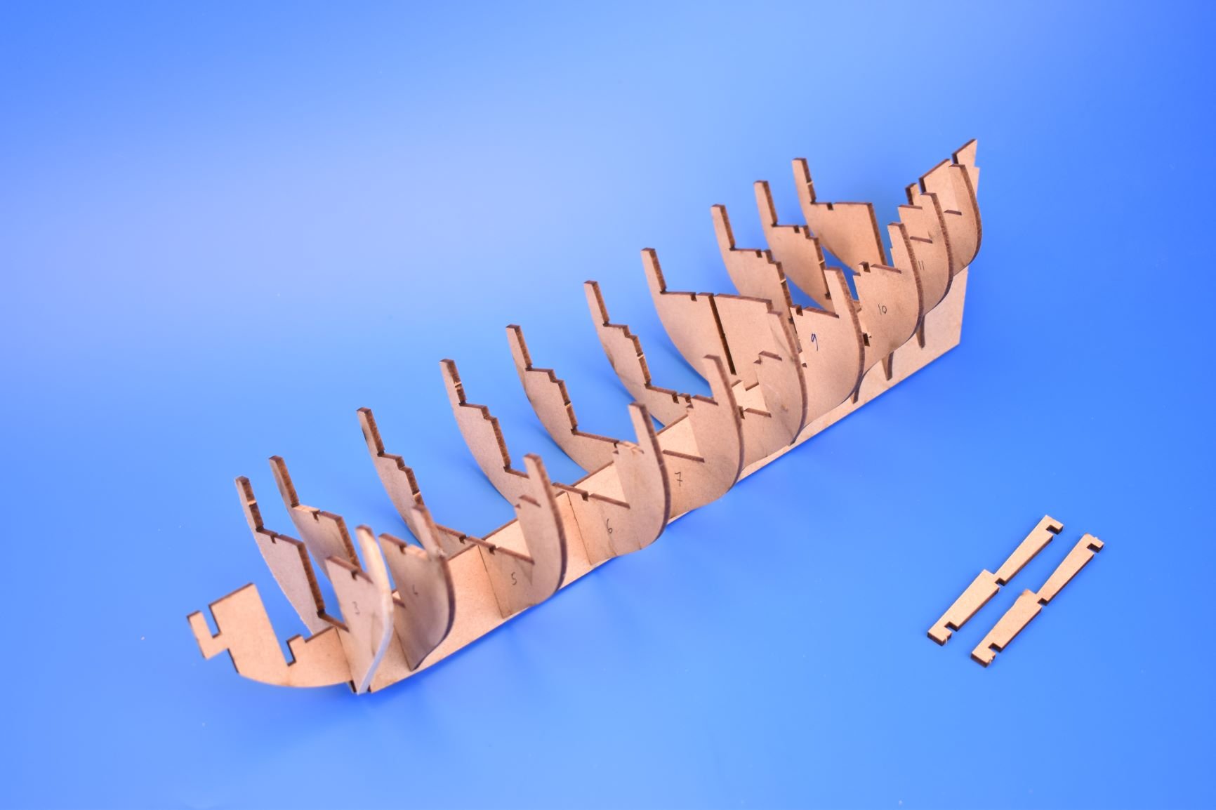
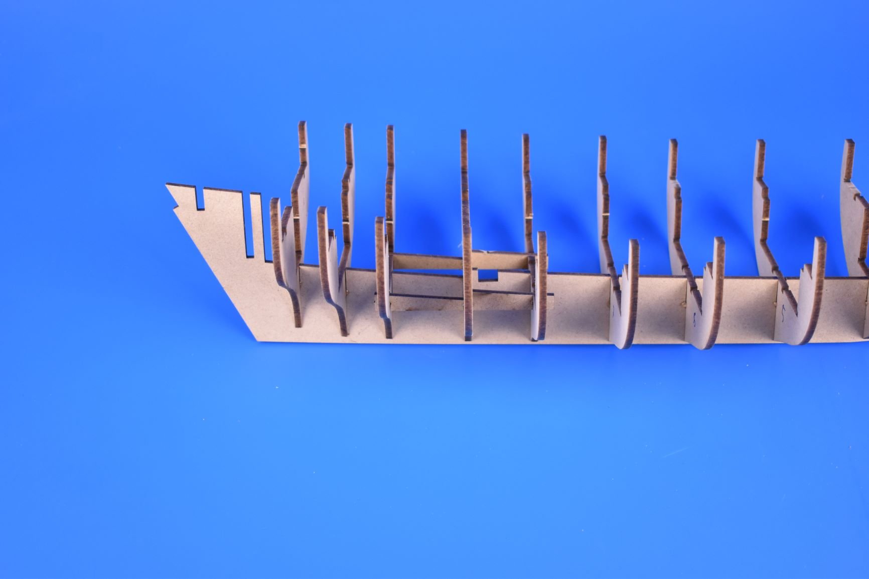
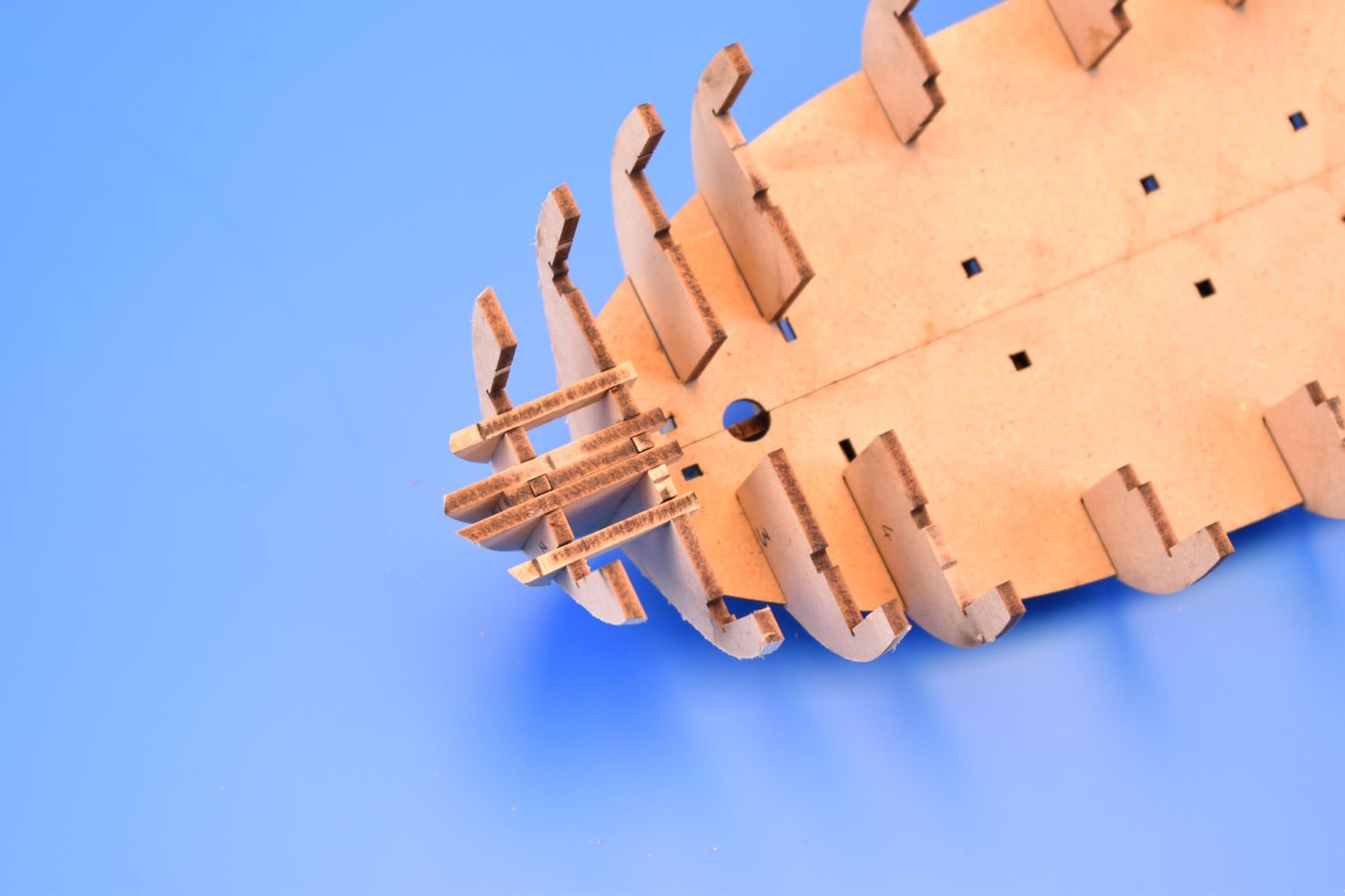
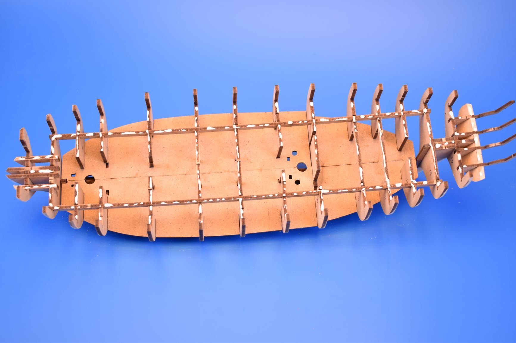
OK, I have put together the basic hull structure, and changed a couple of things since my first build. All of the MDF parts are glued together (superglue gel mostly for a 'speed build').
Everything has gone together fine, no problems. I have changed the stern lower counter and upper stern board. before, the upper pattern was to be added once planked, but I realised just how fragile those stern frames are, more so since I changed them since my first build, to be less unobtrusive. With this in mind, I now show both the stern counter and stern board glued in place as soon as possible, to give the very light and fragile stern area some rigidity. I have also moved these two parts over from the 1mm wood sheet to the 0.8mm plywood sheet, so they have extra strength. The lower decks are the correct height and also have the correct sheers.
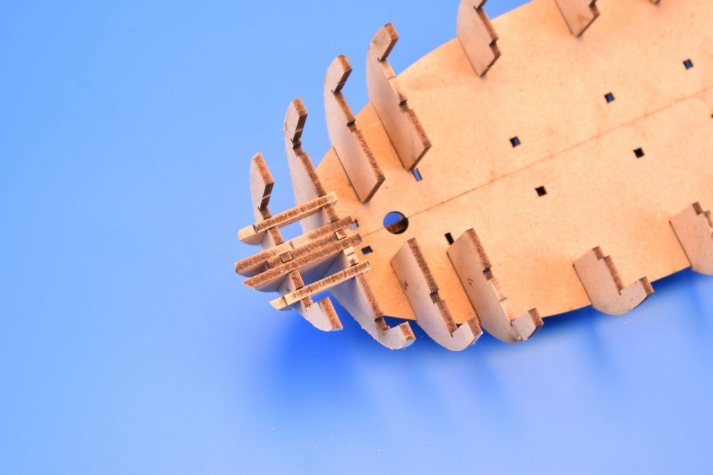
I will add another two tabs to the stem post to minimise it splitting.
I have also attached a pic of my first build, which is in pear, in the process of being sanded after second planking was complete.


- pythagoras, tlevine, Jim Rogers and 25 others
-
28
-
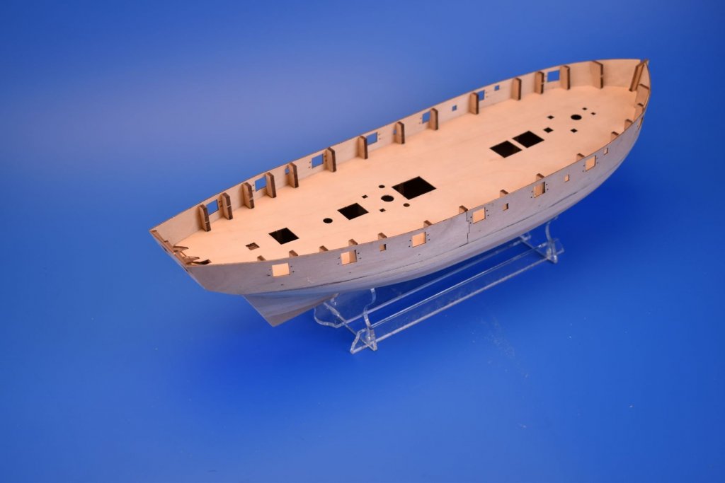
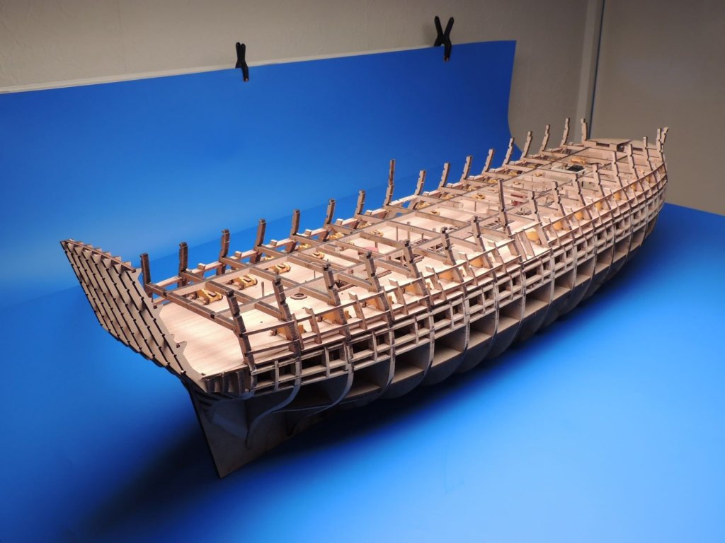
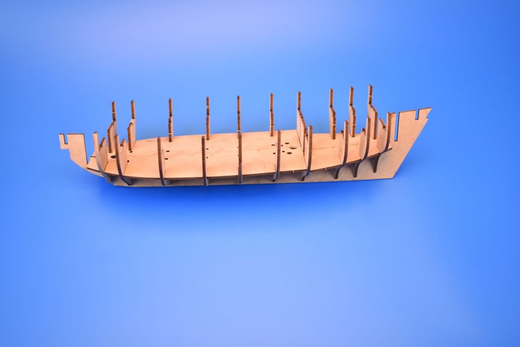
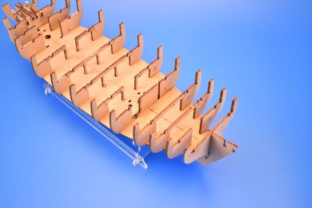
OK, have took half a night from work, to continue with Speedy. From tomorrow, I shall start adding pictures of the development, and you guys can tell me if you like the way it's going, or if there's anything I should change (within reason, don't ask for all exotic wood parts..)
I have already build up one Speedy hull up to the second planking stage, and all was fine. I will now work on this second prototype, which will (hopefully) iron out any little things I may have missed from the first build. I will build this second prototype up to adding the pre-cut gun port patterns, as once that is done, all major structural work is finished, and I shall continue with the first prototype until complete.
I may add another two spacer tabs to the stem post, where the planking slots into, based on what I have seen on the Alert build, to ensure there are no problems with this area.
- Ryland Craze, coxswain, BenD and 5 others
-
8
-
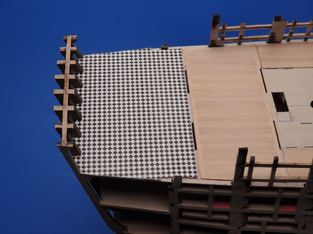
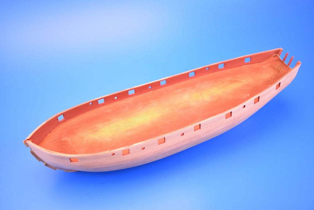
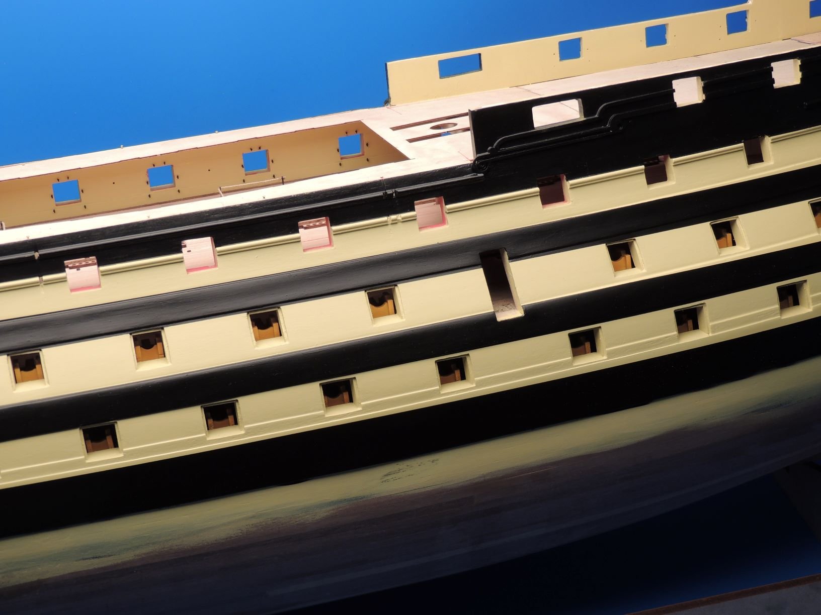
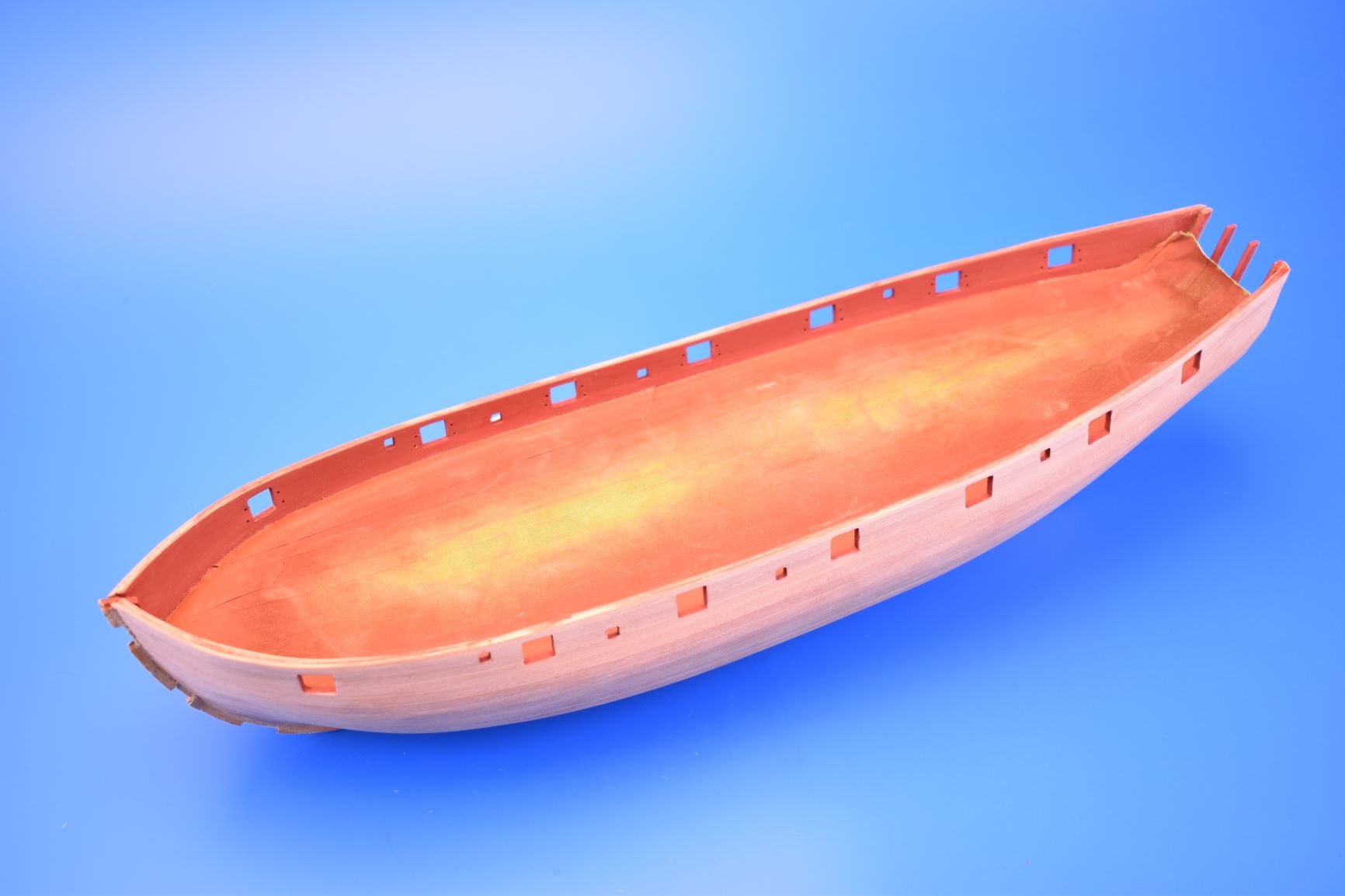
I find the most attractive style is to paint the lower wale black, varnish the hull above, and paint the area above the upper rails black or blue. Before 'Nelson's Chequers', the fashion was actually to paint most of the hulls a red ochre. But looks so much better just varnished..
-
41 minutes ago, Blue Ensign said:
Perhaps it's me then Chris, 🤔,or perhaps my particular stem piece had a grain line in just the wrong place.
As far as medium choice is concerned I do generally agree with you that mdf would restrict those who prefer to varnish rather than paint. I intend to paint this one, (I have Cheerful as an unpainted Boxwood model)
My worry was that the stem would break at a point of no return with some of the planking in place. I do have three strakes in place now and I think the further down the stem I go the less stress on it there will be.
It is clear to see even at this stage she does have very nice lines.🙂
Regards,
B.E.
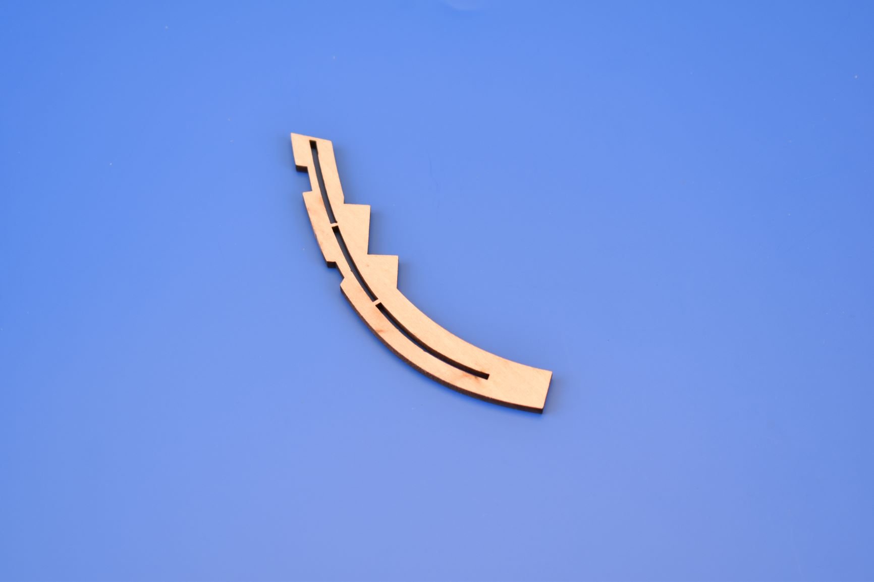
Maybe I should have added extra tabs along the slot length like Speedy's (have attached a pic to show that part). What I did do with Alert was to put the front of the planks into the 3mm MDF pattern (parts 11), leaving enough of a slot for the 1mm outer planking. By the time I got to the second planking, the slot was very secure, due to the glue from the first planking.

-
21 hours ago, Blue Ensign said:
Thank you Chris, my stern frames are now fitted, it's the stem piece (21) that's giving me some concern.
Regards,
B.E.
Sorry to read that, I guess I cannot send another stem post as it is glued in place? If you want another piece, I will happily send another.
I did actually build the hull twice, as I do with all new developments, and I was happy with the slot. I had no problems with it on both hulls I tested, and I am intentionally heavy handed when it comes to parts like this. My impression of the limewood, despite my initial reservations, was that the grain was just as good as other decent woods.
I did toy with using MDF for the stem and keel parts, but I know that more people than not would have hated that, I do not like using MDF for any parts that are shown when the model is complete.
-
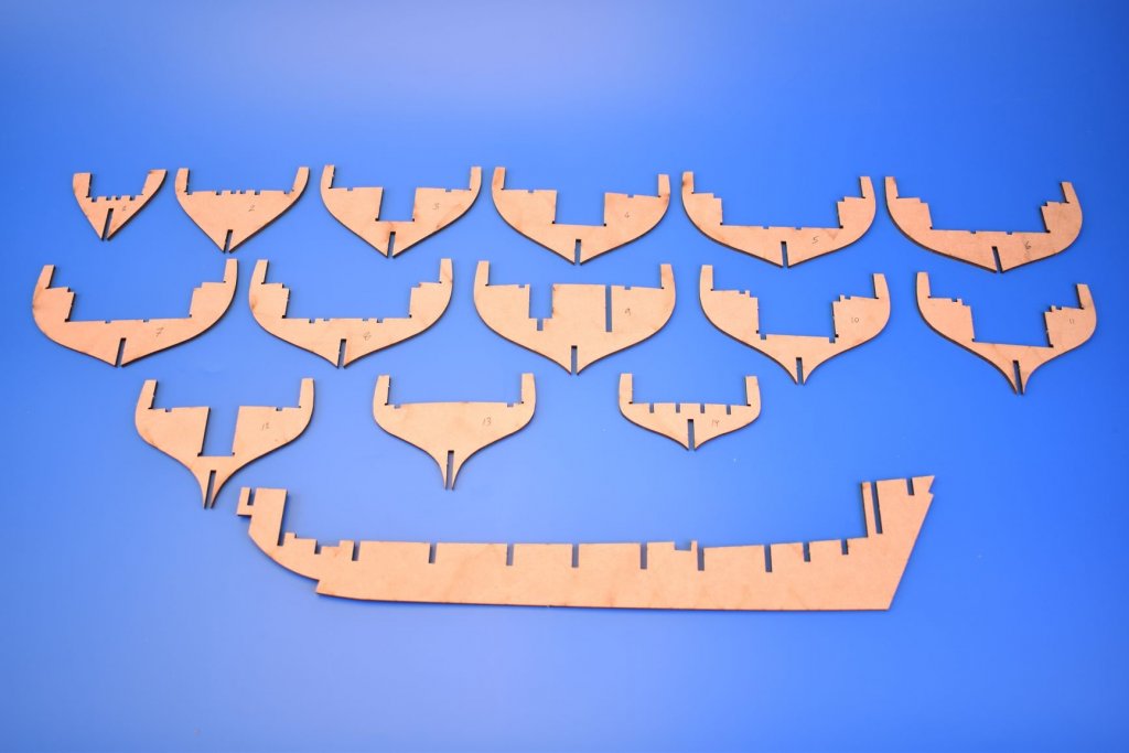
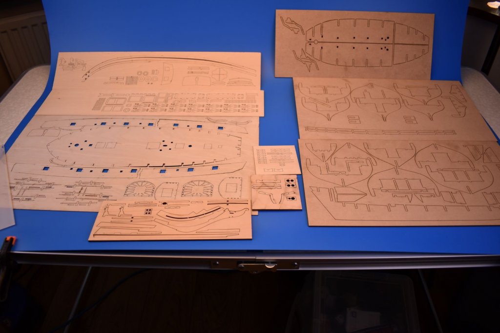
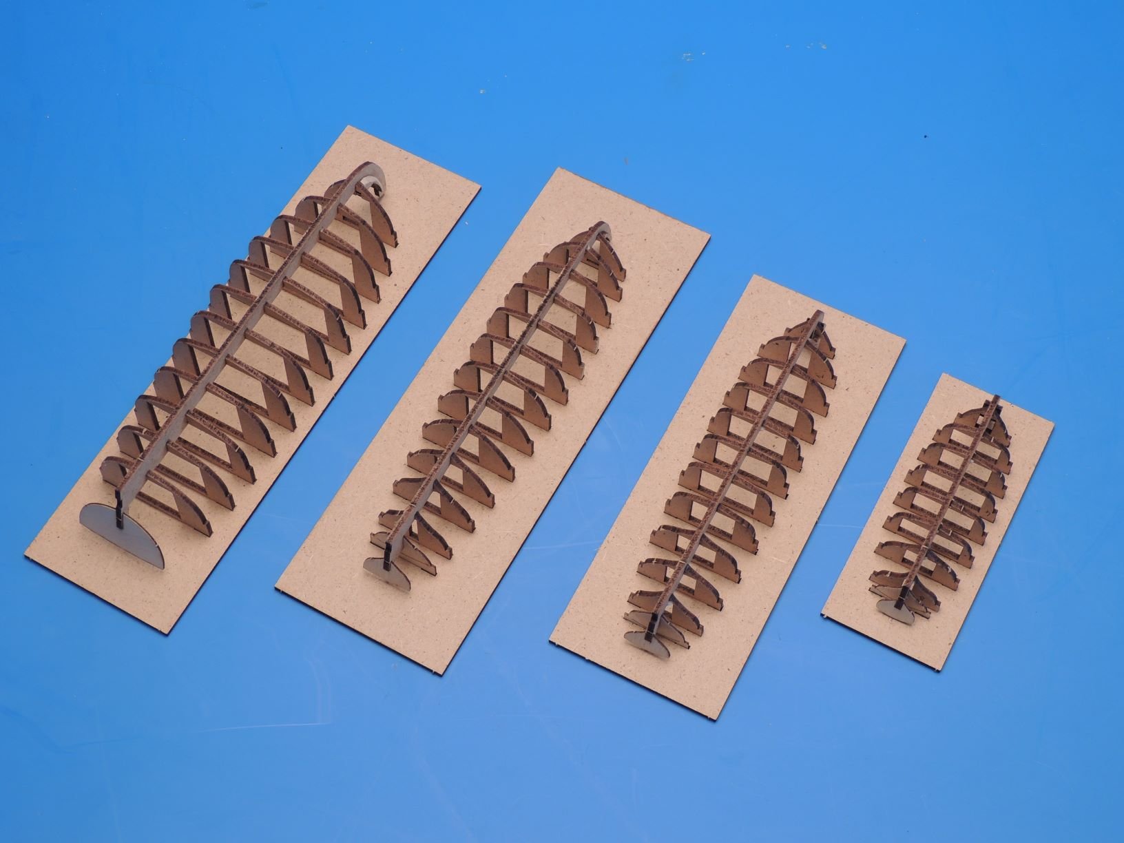
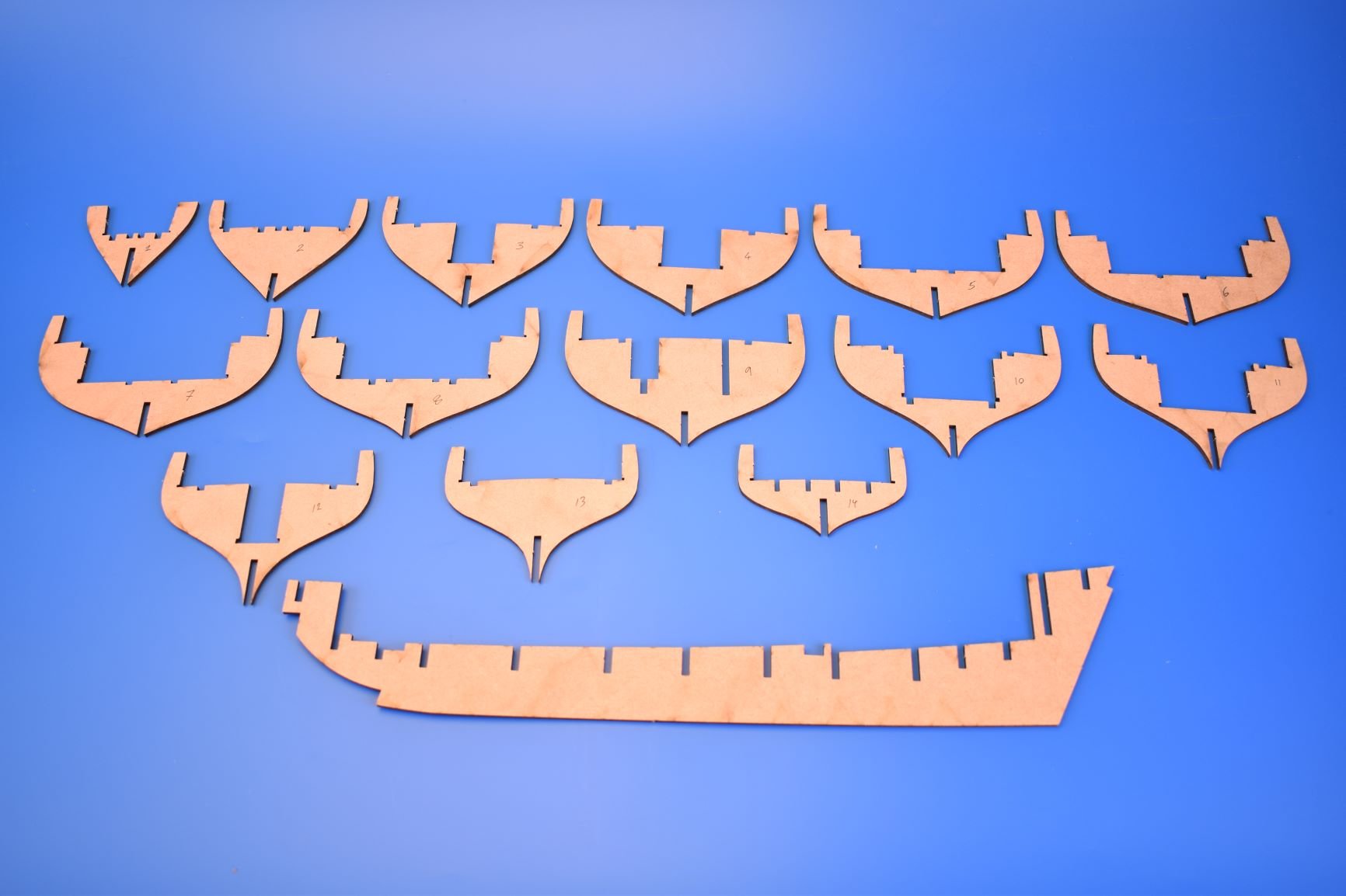
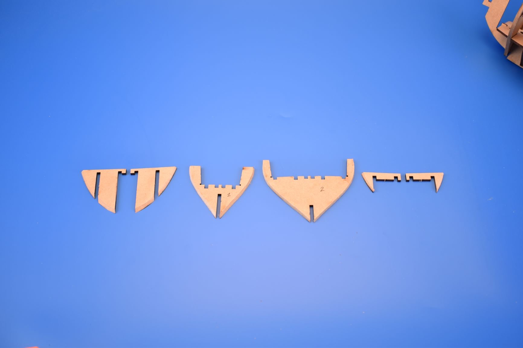
Just had some of the Speedy prototype parts arrive. A lot more parts than Alert, and 15 bulkheads..
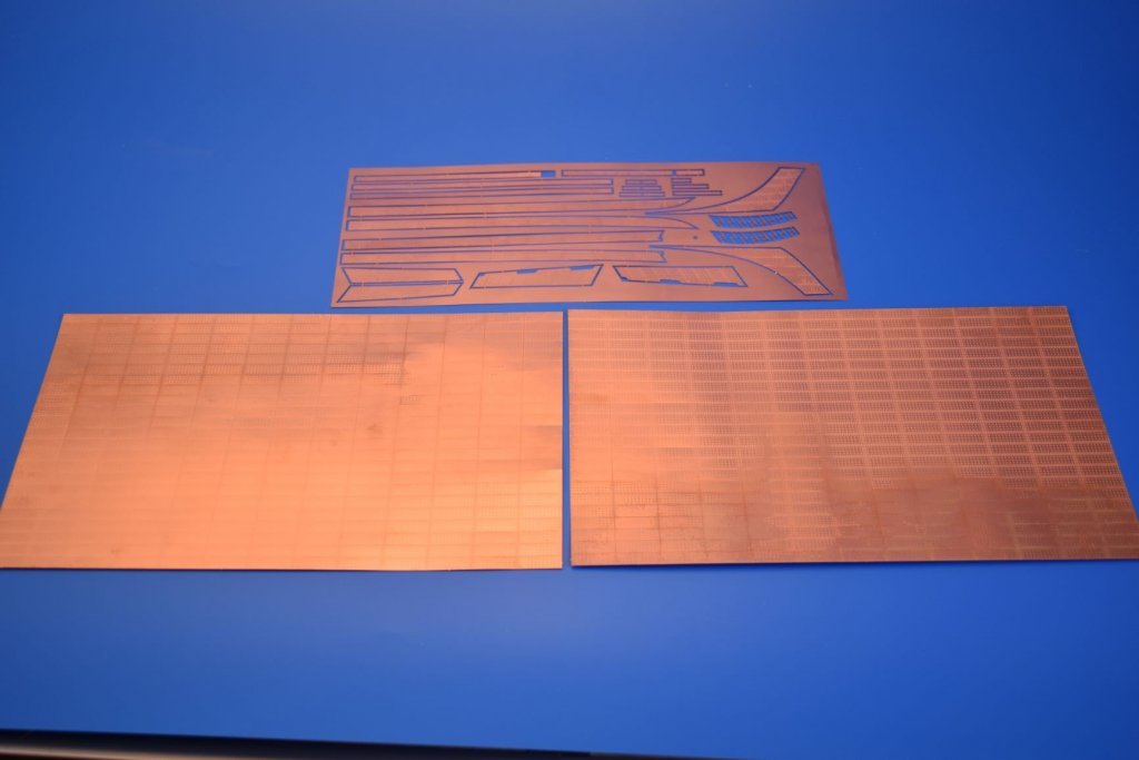
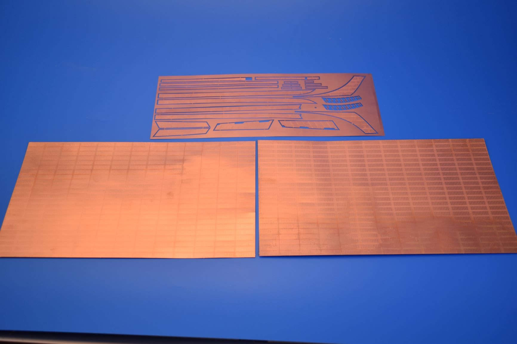
I had one PE sheet missing, so will take a pic of the brass sheets when I receive, but the copper sheets look fine. For the nail heads, I copied exactly a picture I have of an original Victory copper plate.
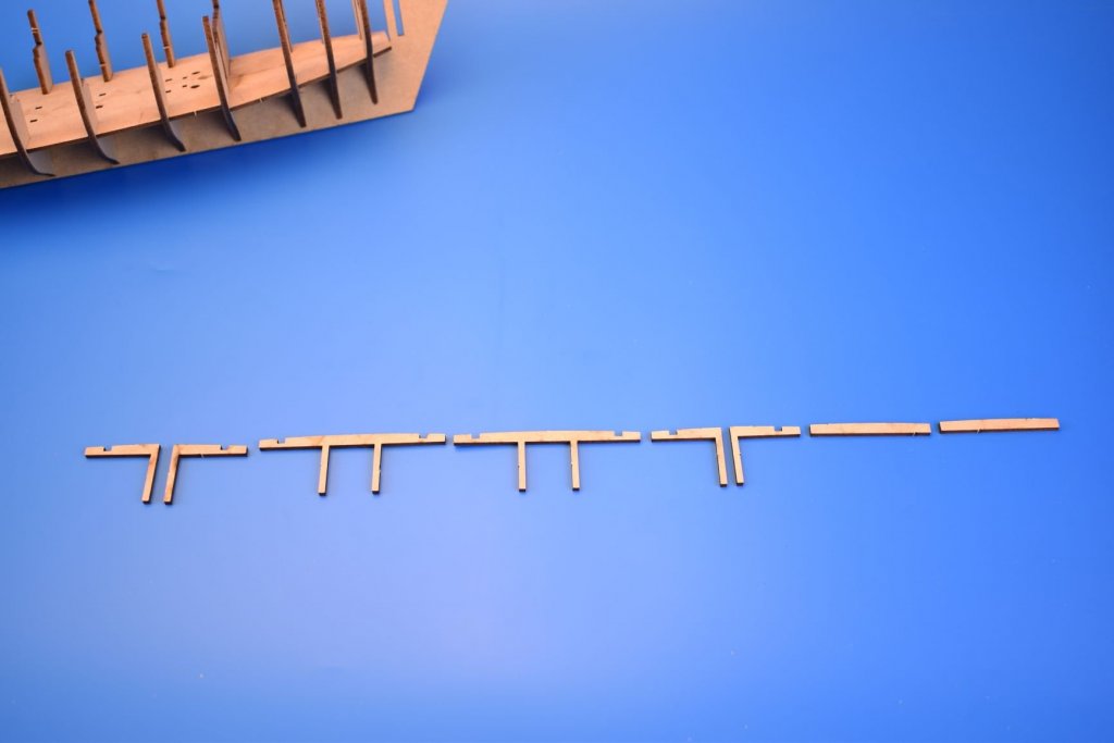
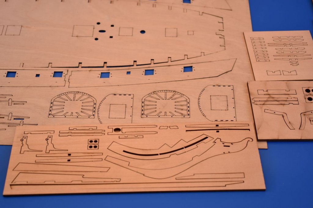
I have tried to make no compromises with this kit, and bought my own supply of 0.8mm ply for the more critical parts. below is not all of the laser sheets, I have the laser engraved deck too. I think I will separate the 1mm wood gunwale into two parts per side, to minimise the chance of it breaking.
I have since removed the holes around the rims of the lower tops, as for the period I am basing the model (1800-1802), crowsfeet would not have been rigged.
I have even included a few hatchets in the 0.4mm PE, as I know they used these to remove tangled rigging when in battle, and Speedy was in battle a lot!


Chris Watton and Vanguard Models news and updates
in Traders, Dealers, Buying or Selling anything? - Discuss New Products and Ship Model Goodies here as well!!
Posted
Cheers! I never intended to do another Speedy, but just do this one up to a certain stage, but realised I could not due to the first prototype showing the stern board glued into position after the second planking was complete. So have no choice but to carry on with this one. Perhaps I will finish the other (pear wood) version as Speedy's sister, Flirt.
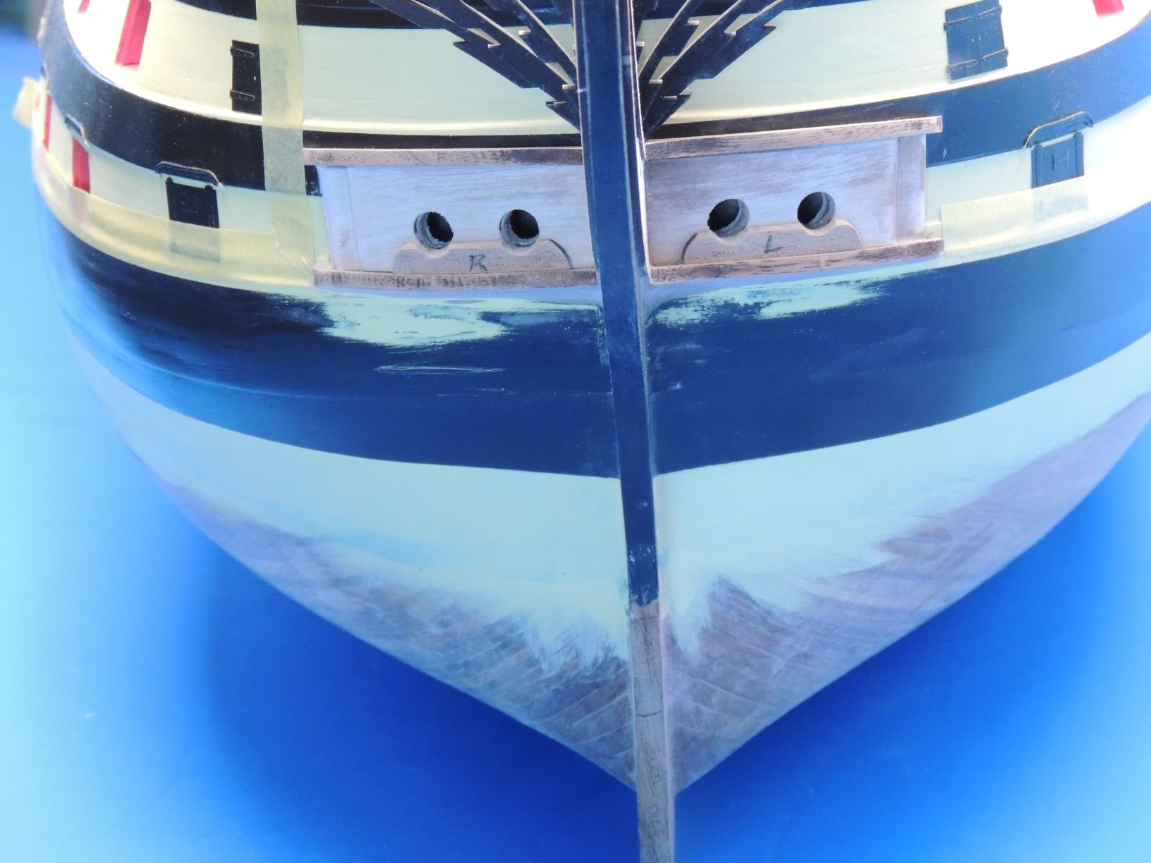
I did think it a mistake to not fix the keel, stern post and prow in place yet, but feel the prow will be vulnerable until all hull planking is finished and sanded - and I cannot add the keel and stern post until the prow is in place.
Planking the inner bulwarks next. Using single strips will be tricky, as the stern is closed off so planks need to be perfect in length. A better solution may be to cut the single planks in half and glue one at the front to half way, and measure up and glue the other half from the stern to the end of the front plank.
If I were building this for a commission, or for myself as a display model, I may take more time, but I just need to build it to look decent for box art. Plus, I know that if I can build it this quick without much trouble, slap it together, as it were, then almost anyone will be able to build it. I have seen what some of you guys can do, and it's much better than some of my efforts.