


vossiewulf
-
Posts
1,477 -
Joined
-
Last visited
Content Type
Profiles
Forums
Gallery
Events
Posts posted by vossiewulf
-
-
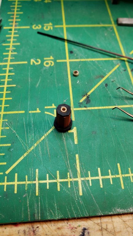
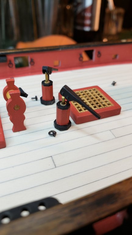
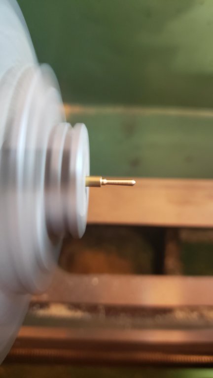
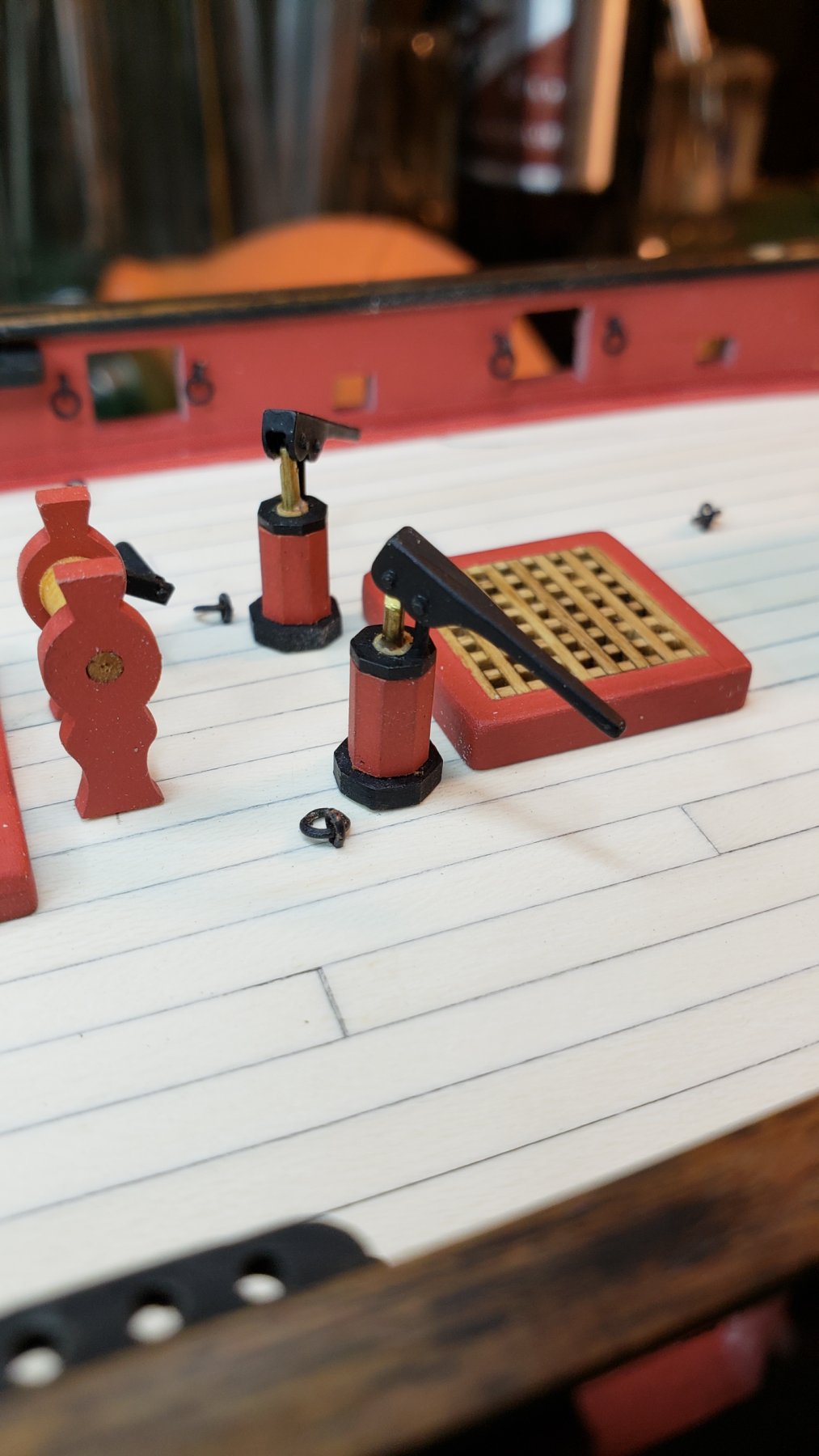
So the little wood bushings for the pumps were pretty small. But they're in place now, I left the center rod brass for no particular reason. That marks us done with deck furniture, I need to repaint the cap rails now and shoot a clear coat over everything, and then I need cannons from Chuck. According to Rick's and Chuck's charts, his 1 11/64" guns would be right for 6 pounders at 1/64. However, it's darkly amusing that the guns will end up costing more than the kit did as I recall
")
- popeye the sailor, Rick01, Ferit and 11 others
-
 14
14
-
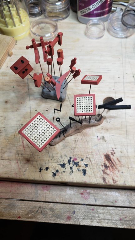
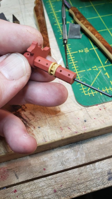
Getting ready for paint finally, using kneaded rubber eraser for my holder. It's much stiffer that plastic or polymer clay, and leaves no residue on your glue sticks or fingers.
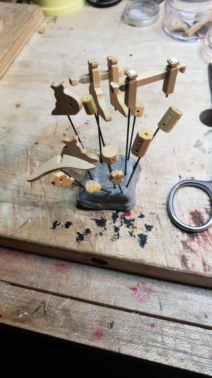
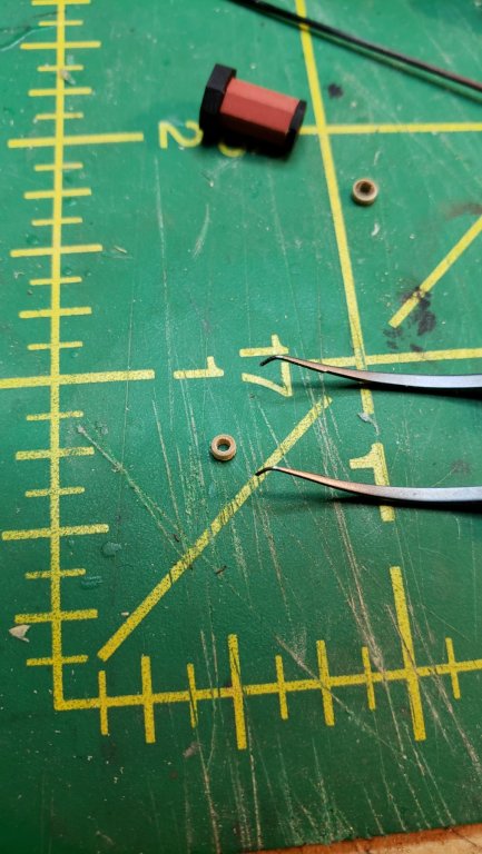
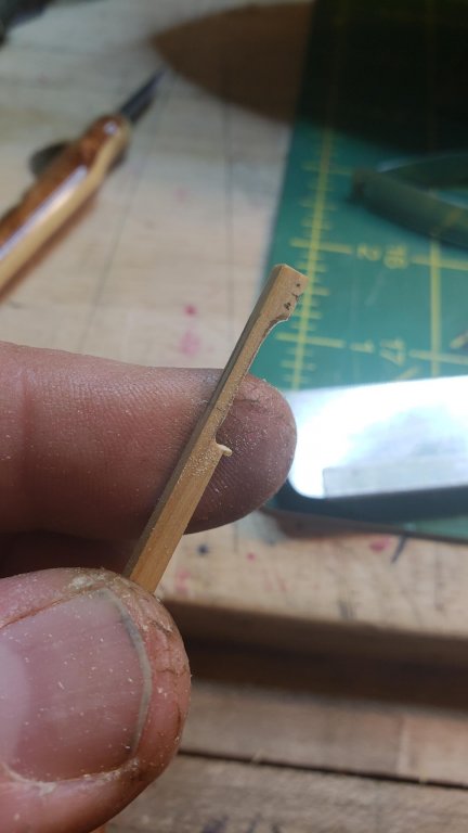
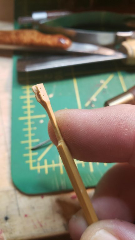
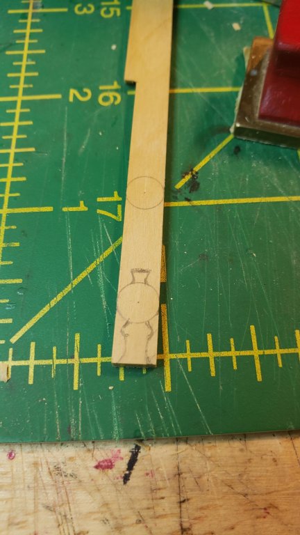
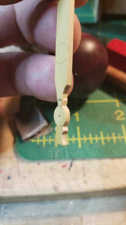
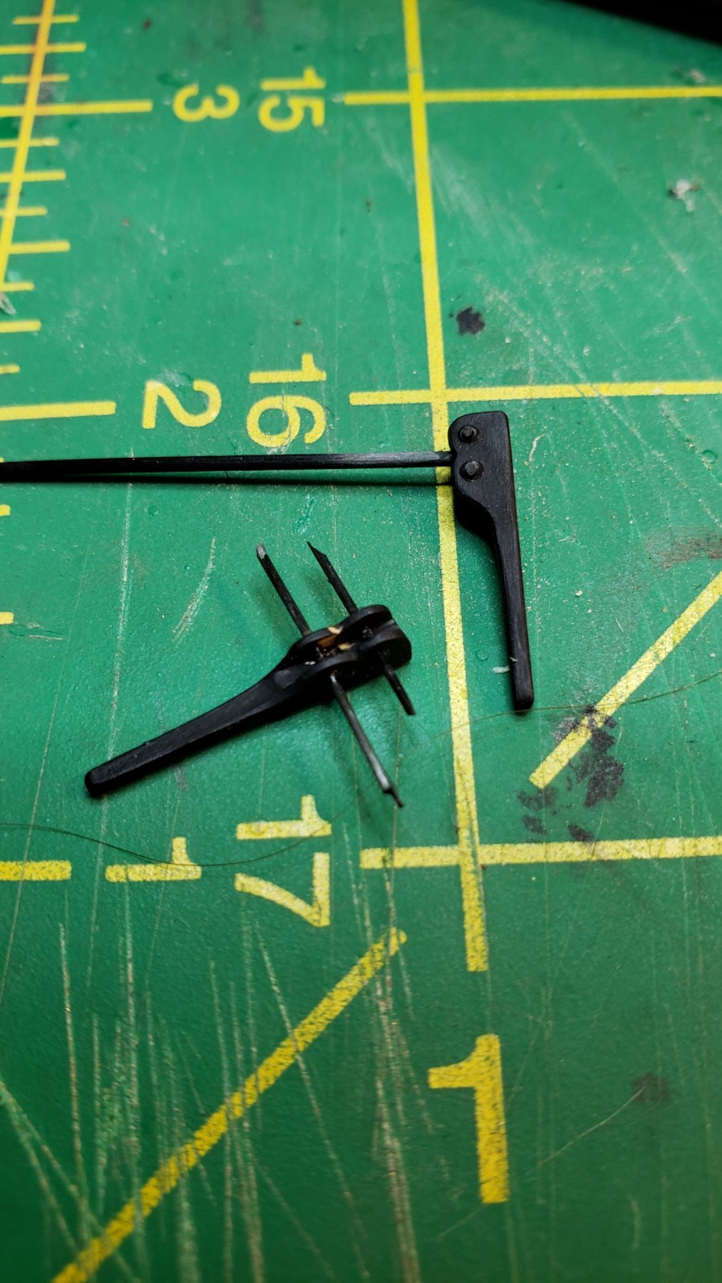
I improved the pump parts, especially the handles that were too heavy, they've been thinned out and made a bit longer. Also drilled out the top pieces to take the circular bushing that goes around the main pump rod..bar... whatever.
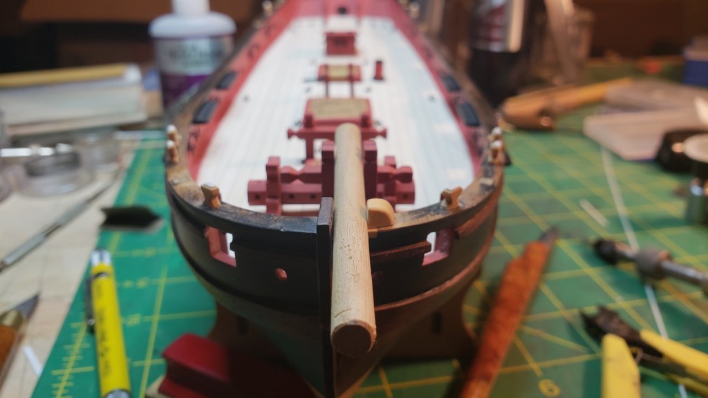
I also added this boomsprit reinforcement that's on trial, this part of the rig has always looked flimsy to me and if I were the captain I'd like a more positive groove for the boom to sit in.
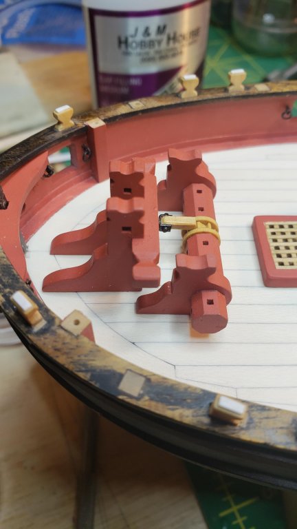
After painting all the red and black. Using some annoying polymer clay because I couldn't find another kneaded rubber eraser, need to order more.
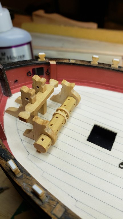
Finally able to start gluing up sub-assemblies. The non-painted wood parts got a coat of Minwax golden oak.
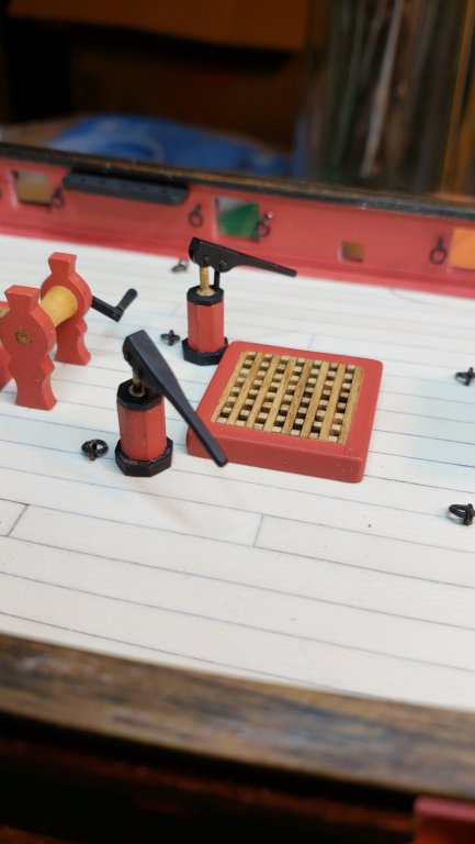
Boomsprit support and anchor windlass in place, with pawl engaged.
Grates, bitts, windlass, and companion installed, pumps being assembled.
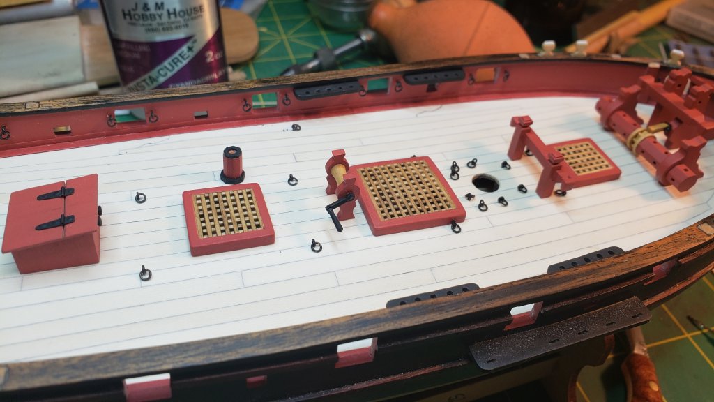
Was very careful to ensure perfectly straight alignment for the boomsprit.
- KeithAug, jwvolz, paulsutcliffe and 16 others
-
19
-
Two very detailed episodes totaling 1:20:00.
- thibaultron, mtaylor, Mike Y and 1 other
-
4
-
Welcome, being a stickler for detail is pretty much endemic in this crowd, so don't feel unusual
I will give you what I have learned working through my build: the really successful builders build the entire ship, down to every detail and process, in their heads before they start. If you start working thinking that you can figure something out when you get there, you will get bitten. For example, the Lady Nelson is a nice kit but the stern is really inaccurate for cutters of the period. If I had taken the time to research the contemporary models first, I could have corrected it, instead I worked ahead and by the time I realized that, it was too late for the major surgery required.
Starting scratchbuilding is ambitious and honestly risky, but if you have previous skills it may be ok. If you are starting totally from scratch with no experience building models of any kind, I'd suggest you try a kit. The new Master Korabel kits have every plank laser cut and seem to go together very easily compared to other kits and they produce a fine-looking output- if I'd known about them I might have started there. Regardless, good luck and have fun, that's the purpose.
-
Rick did you use the guns from the kit? They're not bad, but I think we could do better with guns from Chuck. However, when I go check his gun offerings, all are much bigger than the 11/16"/17mm of the kit guns. I thought the kit guns were supposed to be 6 pounders, but maybe they're three pounders, only thing I can think of. The only thing he offers at that size is designated a swivel gun and won't have a carriage.
-
-
I swore I had seen similar windlasses on other contemporary models, but I guess I was wrong. In this case I don't care, I made one and I like it so it's going midships near the pumps just like on Trial. Maybe on this boat they ran a line through some fairleads over the side and used it to fish for tuna
-
Very nice method, thanks.
- BETAQDAVE, Keith Black, thibaultron and 1 other
-
4
-
20 minutes ago, harlequin said:
cheers kier......I wouldn't say great .... more of a how did I manage that ? corel kit builder..
It looks to me like you've done a very good job, I've never heard anyone talk about how easy Corel kits are to build and yet your ship is very clean and straight and pretty Bristol fashion to my eye.
-
Good luck! Actually, for the first layer of planks you can "cheat" and use easier methods since the point is just to get a good substrate layer for the final planking, but like you since I'd never planked a ship, I used the first planking to figure out this whole ship planking thing in hopes I would have a reasonable grasp for the final planking.
The method you stumbled on of using hot water, a hair dryer, and leaving clamped to cool is one of the preferred planking methods and will work well. However don't assume spiling is always necessary, planks will edge-bend (within limits) just fine with the same hot water or steam methods. I in fact did not spile a single plank for the second boxwood planking of my Lady Nelson. That wouldn't be possible with anything with a fuller bow, but it does demonstrate that if a plank has a gentle edge sweep, that can be handled like any other bending.
-
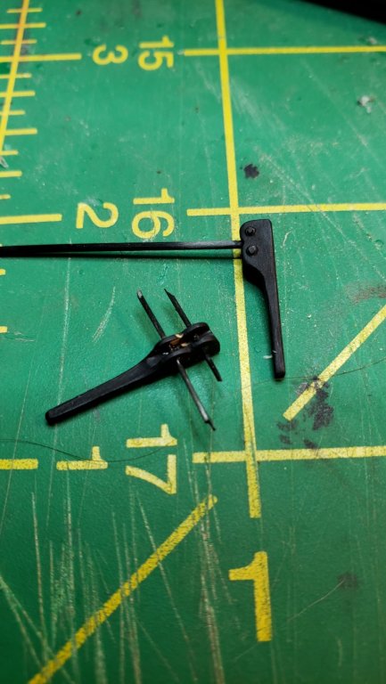
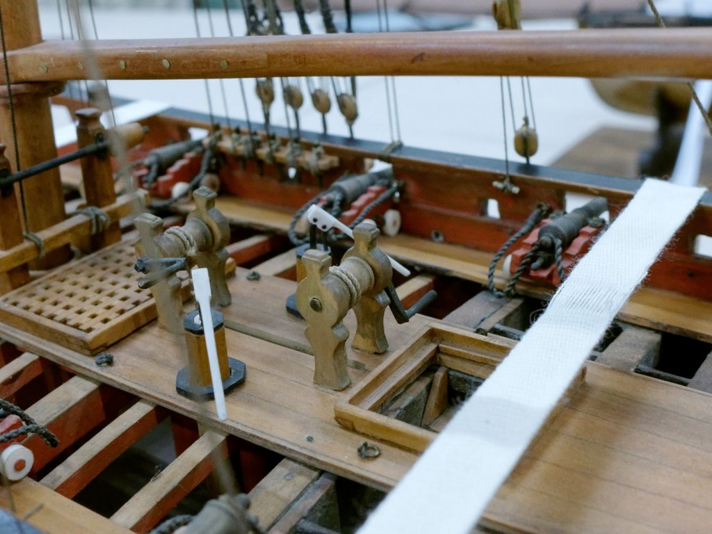
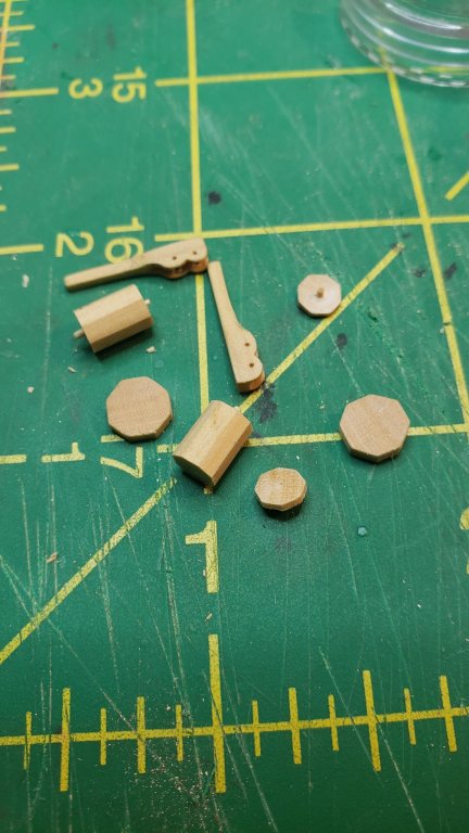
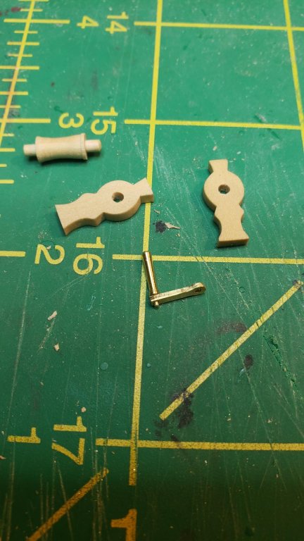
Pump handles and pump parts, and the small windlass that will go mid deck, I'm including one of Tony's pics to show what I'm trying to follow.
If the method to the madness isn't obvious, I've been making all the parts required for the deck furniture up to the point at which they need paint, and stopped there, the point being to minimize my opportunities to break things already installed. I've now made the final pieces and I will be painting most everything black or red, then each of the subassemblies will be installed bow to stern.
I've decided to not do much about the stern other than adding some thickness to the transom so it doesn't look like it will collapse at the first wave over the stern. If the transom was flatter I'd consider major surgery to cut it down and add a cap rail, but with it so curved we'd end up with a Seppings round stern on a cutter and that's just replacing one unrealistic thing with another. I wish I'd spent more time early looking at contemporary models instead of trusting to a reputable kit manufacture and kit designer for that matter, I don't think this is Chris Watton's greatest work.
One thing I've learned about ship modeling is that to be fully successful, you have to build the entire model down to every detail in your head before you build anything, including working out all the required processes and tools and materials. Assuming you will figure out something when you get there will result in the gods of ship modeling smiting you a good one.
-
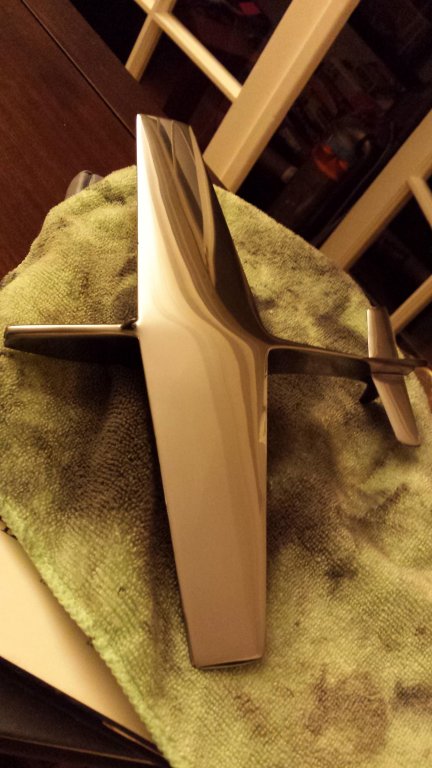
Uschi is definitely the place to go for woodgrain decals, paints, and metal finishes. The metal powder finishes are very easy to use and produce spectacular results. Below was me playing around with them, I made a balsa wood glider, filled the pores with lots of sanding sealer, painted Tamiya flat black over everything and then burnished that down (Tamiya flat black is soft and can be burnished out to a still-soft semi-gloss or gloss), and then rubbed in some of Uschi's aluminum powder. Once I was done I couldn't tell it wasn't solid highly polished aluminum.
Tragically the balsa proved much too unstable for that level of surface smoothness, after I set it aside for a month all sorts of ripples started to appear. But certainly styrene and resin and acrylic and other easily workable substrates can be made into complex parts that are indistinguishable from solid metal.
-
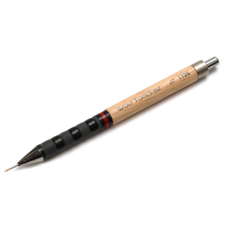
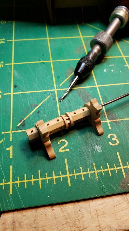
An extremely precise and handy tungsten scriber. This is now my awl for all small drill holes and I've been using it for general marking on wood also, the consistent fine line can be highlighted if necessary by running a pencil gently down it.
- mtaylor, Ryland Craze, CDW and 6 others
-
9
-
If it doesn't qualify as a masterpiece, I'm not sure what does. I have not the slightest idea how you managed to achieve some of the carving, particularly what appears to be long lengths of carved rope.
I also agree with LH that there aren't many comments because your skill level places you in a completely different league from most of us here, you are playing in the Bundesliga and in comparison, we are playing in the fourth division in Finland. It's hard to say much useful other than "wow".
-
-
It's a rusted electrified power egg, obviously.
- mtaylor, keelhauled, Piet and 2 others
-
5
-
Extremely good work. You make that joinery sequence look easy.
- mtaylor and Keith Black
-
2
-
No glue yet, but Trial has them lined up all the way across. Or at least the outboard one on the port side lines up with the inboard section on the starboard side, which are the only two I can see on Tony's pics.
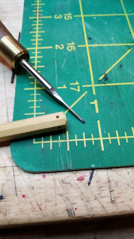
I knew about the nail trick, but wanted to play with Mikhail's chisels
It wasn't that hard, one of the chisels was exactly the right size and I matched a drill bit to it so the squaring required very little removal of wood.
-
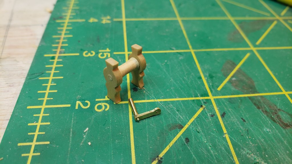
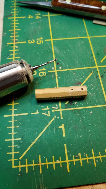
Progress has been a bit slow since work is being busy, but I've made everything at this point except the pumps and a small windlass I'm going to add below the spanker boom as seen in the model of Trial. Actually almost all of them have more than one small windlass on deck, but there isn't room between the anchor windlass and the forward grate on LN to fit the one typically seen forward.
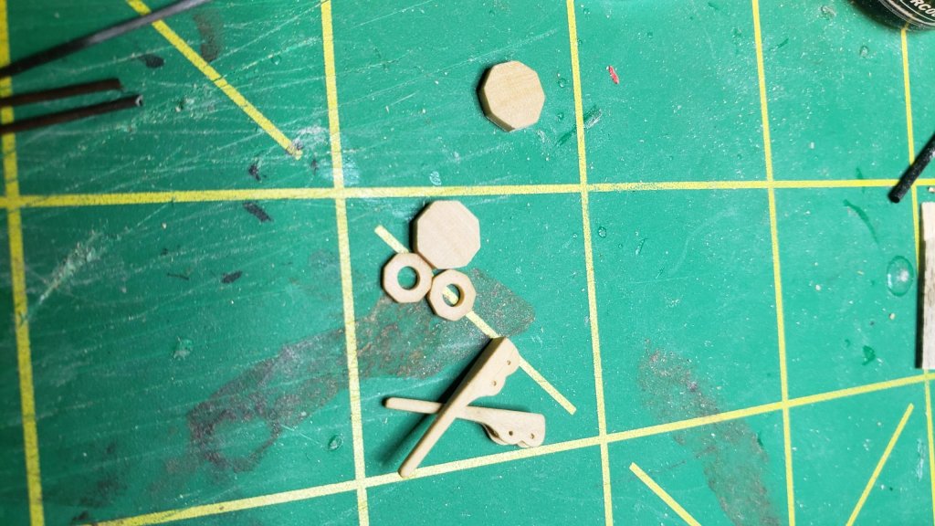
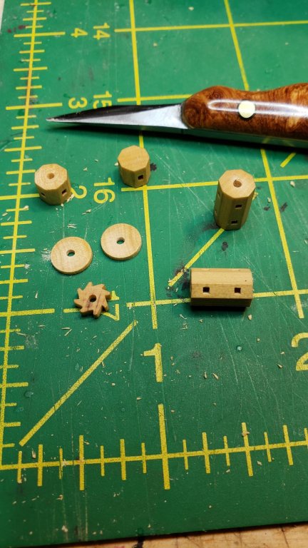
The anchor windlass started with an octagonal section of boxwood. I just marked an octagon on each end and did it by hand with one of my small planes, it wasn't hard. I then drilled holes for the windlass bars, and squared them off using one of Mikhail's small chisels. To prevent tearout, I "crosscut" the piece into the various required sections on the lathe, and also made a couple round slices from another piece of boxwood to go on each side of the ratchet gear.
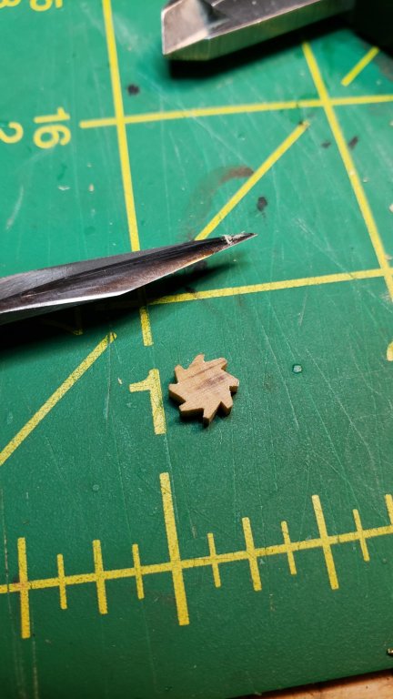
The ratchet gear itself is just a slice from the starting octagonal piece that I carved with a knife.
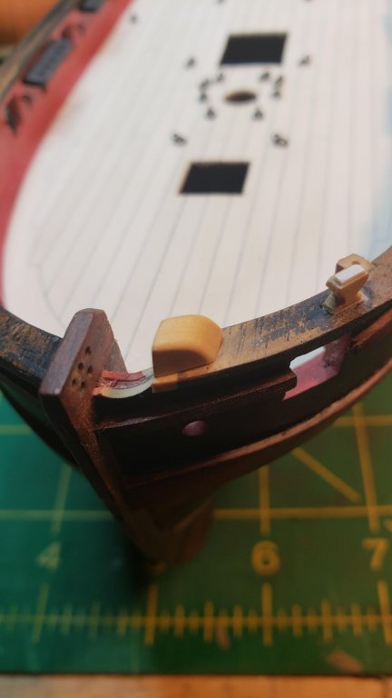
Test fitting, it's missing its starboard end piece here. Also, the cross piece on boom support of Trial is much lower than that on LN, and the pawl for the windlass ratchet attaches to that cross piece. So in my case, no pic but I've added a small piece to the centerline boom support and the pawl will attach to that. I also stuck with a single ratchet, whereas Trial has two.
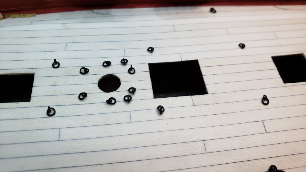
And I also took a couple evenings and made and soldered rings for all of the eyebolts on deck.
- src, MEDDO, popeye the sailor and 7 others
-
10
-
14 hours ago, BANYAN said:
Your joinery is
an inspiration!proof you are an 8-armed alien posting to Model Shipworld from the orbit of SaturnFixed that for you.
- Obormotov, mtaylor, Bluto 1790 and 1 other
-
4
-
-
Beautiful work Kortes. These are very odd boats- hull turned almost into a circle, everything on the hull is sweeping curves whether it makes sense or not, but then we come to a bowsprit that is stark square-sectioned black iron with solid iron bar stays, it's like a section of prison wall bolted to the bow
- Keith Black, mtaylor, druxey and 4 others
-
7
-
-
If you look at the real deck planking patterns of the Vasa or the Mary Rose, you'll stop worrying about it
It seems the driving concept of the period was to use whatever they had at hand, including 2 foot planks and wide planks and really narrow planks, fit together like the decks were done on All You Can Drink Free Beer day.
- pontiachedmark, mtaylor, russ and 1 other
-
4


MONTAÑES by Amalio
in - Build logs for subjects built 1751 - 1800
Posted
That much joinery, all of it completely flawless... I'm still going with Amalio being an eight-armed alien. Maybe 12 arms. And at least 16 eyes.