BobG Posted February 6, 2020 #631 Posted February 6, 2020 Unbelievably beautiful, Chuck! There is no doubt that I will have to have a go at the Winnie someday. You've set the bar so high it's a bit intimidating though! Bob FrankWouts and Chuck 2 Bob Garcia "Measure once, cuss twice!" Current Builds: Hms Brig-Sloop Flirt 1782 - Vanguard Models Pen Duick - Artesania Latina 1:28 Completed: Medway Longboat 1742 - Syren Ship Model Co. Member of the Nautical Research Guild
Chuck Posted February 6, 2020 Author #632 Posted February 6, 2020 thanks guys. Its not too tough Bob. Its about the same difficulty as my other designs like the long boat. Just bigger with more parts. no more difficult to build in my opinion...but i am probably not the best person to ask since I designed it. EricWilliamMarshall, Ryland Craze, BobG and 2 others 5 Chuck Passaro - MSW Admin Sloop Speedwell - POF scratch Block Island Boat - POF scratch HMS Winchelsea - POB scratch build HM Cutter Cheerful - POB scratch build Royal Barge - POF scratch Medway Longboat- POF Scratch SYREN SHIP MODEL COMPANY
ChrisLBren Posted February 6, 2020 #633 Posted February 6, 2020 Im really curious about the paper patterns - how do you not get glue bubbles when applying and also would it be possible to put a finish over them ( dont think that would work due to printer ink) FrankWouts 1
Chuck Posted February 6, 2020 Author #634 Posted February 6, 2020 Try not to over think it. Never got any bubbles. Not even a little bit. I just use a glue stick. Works perfectly. Make sure no lumpy glue. Stick it on. Its really that simple. For a finish I spray them with matte fixative and let them dry before cutting them out. if you are curious....print one out and glue it to some scrap as a test. It should answer all your questions. Spray mount would also work but less open time. With the glue stick you can move it around and slide it before it sets. Dowmer, Ryland Craze, Stuntflyer and 3 others 6 Chuck Passaro - MSW Admin Sloop Speedwell - POF scratch Block Island Boat - POF scratch HMS Winchelsea - POB scratch build HM Cutter Cheerful - POB scratch build Royal Barge - POF scratch Medway Longboat- POF Scratch SYREN SHIP MODEL COMPANY
BobG Posted February 6, 2020 #635 Posted February 6, 2020 5 hours ago, Chuck said: thanks guys. Its not too tough Bob. Its about the same difficulty as my other designs like the long boat. Just bigger with more parts. no more difficult to build in my opinion...but i am probably not the best person to ask since I designed it. Thanks, Chuck, for the encouragement. I've been learning a ton building the Medway Longboat but it hasn't been without some errors on my part even though I've been trying my level best. When I look at the photos of your Winnie build, it simply looks perfect. I can't imagine it could be any better and I have a hard time imagining that I could come close to that level of craftsmanship. It just looks so beautiful that I worry that I just wouldn't do it justice or, at least, wouldn't be able to do it as well as I would like. I think I'm my own worst critic, which can serve me well in striving to get better but it can get in the way of me being satisfied also. I'm working on it though! Bob FrankWouts 1 Bob Garcia "Measure once, cuss twice!" Current Builds: Hms Brig-Sloop Flirt 1782 - Vanguard Models Pen Duick - Artesania Latina 1:28 Completed: Medway Longboat 1742 - Syren Ship Model Co. Member of the Nautical Research Guild
BobG Posted February 6, 2020 #636 Posted February 6, 2020 5 hours ago, ChrisLBren said: Im really curious about the paper patterns - how do you not get glue bubbles when applying and also would it be possible to put a finish over them ( dont think that would work due to printer ink) I used the glue stick method on my Medway Longboat and it worked very well. I found it easy to remove even after I had applied it also. I didn't like how the frieze looked on the stern the first time I glued it on. I didn't have it with equal symmetry around the edges so I pulled it off and cleaned the stern up with a moistened cloth. Then I printed another set off patterns and was more careful in my application of the frieze and trimming it to get it centered nicely. I did forget to spray it with fixative before I applied it and now I'm wondering if there is a way to seal it without masking it all off and spraying fixative on it...brush it somehow with fixative...??...or just leave it be? FrankWouts 1 Bob Garcia "Measure once, cuss twice!" Current Builds: Hms Brig-Sloop Flirt 1782 - Vanguard Models Pen Duick - Artesania Latina 1:28 Completed: Medway Longboat 1742 - Syren Ship Model Co. Member of the Nautical Research Guild
Beckmann Posted February 6, 2020 #637 Posted February 6, 2020 (edited) What an excellent and beautiful design!! We are lucky to participate in this, thanks Chuck! Will you leave this black hole for the rudder like it is, or open it later? Edited February 6, 2020 by Beckmann FrankWouts 1
Chuck Posted February 6, 2020 Author #638 Posted February 6, 2020 It will be opened. But that will be done later. FrankWouts 1 Chuck Passaro - MSW Admin Sloop Speedwell - POF scratch Block Island Boat - POF scratch HMS Winchelsea - POB scratch build HM Cutter Cheerful - POB scratch build Royal Barge - POF scratch Medway Longboat- POF Scratch SYREN SHIP MODEL COMPANY
Chuck Posted February 6, 2020 Author #639 Posted February 6, 2020 Thank you all for the kind words!!!! and Likes!!! I think its time to move inboard and get some work done. Beckmann, Dowmer, FrankWouts and 8 others 11 Chuck Passaro - MSW Admin Sloop Speedwell - POF scratch Block Island Boat - POF scratch HMS Winchelsea - POB scratch build HM Cutter Cheerful - POB scratch build Royal Barge - POF scratch Medway Longboat- POF Scratch SYREN SHIP MODEL COMPANY
KirbysLunchBox Posted February 22, 2020 #640 Posted February 22, 2020 I have been away from the site for a bit. I came back and started binge reading through my favorite build logs from before I left. Went looking for your cheerful log and found this. Loving it. Came to the last page with sadness and now I can’t wait to see this come to completion! Amazing work! Thank you! Chuck and FrankWouts 2 ~Kirby
Chuck Posted February 22, 2020 Author #641 Posted February 22, 2020 Thank you very much....and welcome back. FrankWouts 1 Chuck Passaro - MSW Admin Sloop Speedwell - POF scratch Block Island Boat - POF scratch HMS Winchelsea - POB scratch build HM Cutter Cheerful - POB scratch build Royal Barge - POF scratch Medway Longboat- POF Scratch SYREN SHIP MODEL COMPANY
KenW Posted February 26, 2020 #642 Posted February 26, 2020 I saw the model last night. It looks even better in person. WOW! EricWilliamMarshall, Rustyj, FrankWouts and 3 others 6 Ken NO PIRACY 4 ME! (SUPPORTING CHUCKS' IDEA) Current Build: Washington 1776 Galley Completed Builds: Pilot Boat Mary (from Completed Gallery) (from MSW Build) Continental Boat Providence (from Completed Gallery) (from MSW Build) Continental Ship Independence (from Completed Gallery) (from MSW Build) Rattlesnake (from Completed Gallery) (from MSW Build) Armed Virginia Sloop (from Completed Gallery) Fair American (from Completed Gallery) (from MSW Build Log) Member: Ship Model Society of New Jersey Nautical Research Guild
Chuck Posted February 26, 2020 Author #643 Posted February 26, 2020 Thanks Ken!!!! FrankWouts and KenW 2 Chuck Passaro - MSW Admin Sloop Speedwell - POF scratch Block Island Boat - POF scratch HMS Winchelsea - POB scratch build HM Cutter Cheerful - POB scratch build Royal Barge - POF scratch Medway Longboat- POF Scratch SYREN SHIP MODEL COMPANY
ir3 Posted February 28, 2020 #644 Posted February 28, 2020 Hi Chuck, I just noticed that the parts for chapter 3 are already sold out. Will you have more available soon. I check the SYREN site regularly and I just must have missed it. Thanks, Iran FrankWouts 1
Chuck Posted February 28, 2020 Author #645 Posted February 28, 2020 Maybe in a week or so. I am pretty sure most you guys arent ready for them yet so there is no hurry to buy them. In fact it might be better to wait until you are nearly ready for them because by that time I may have the parts available for chapter four also. Chuck FrankWouts, Matt D and Rustyj 3 Chuck Passaro - MSW Admin Sloop Speedwell - POF scratch Block Island Boat - POF scratch HMS Winchelsea - POB scratch build HM Cutter Cheerful - POB scratch build Royal Barge - POF scratch Medway Longboat- POF Scratch SYREN SHIP MODEL COMPANY
Jim Rogers Posted February 28, 2020 #646 Posted February 28, 2020 When will chapter three be released for print? FrankWouts 1 Regards, Jim Rogers Damn the Torpedoes , Full speed ahead. Adm David Farragut.
Chuck Posted February 28, 2020 Author #647 Posted February 28, 2020 Cant say really. I am still writing it. But not too long. I am confident it will be ready sooner than anyone will need it. Matt D, Rustyj and FrankWouts 3 Chuck Passaro - MSW Admin Sloop Speedwell - POF scratch Block Island Boat - POF scratch HMS Winchelsea - POB scratch build HM Cutter Cheerful - POB scratch build Royal Barge - POF scratch Medway Longboat- POF Scratch SYREN SHIP MODEL COMPANY
Chuck Posted March 22, 2020 Author #648 Posted March 22, 2020 Just another quick note to make sure everyone checks and corrects the angle of their stern frames. If you pushed back those outside stern frames when you framed the q galleries, you will run into problems later on. In addition, be sure to fair the width of those outside stern frames properly to match the width shown on your plans. This will also have an impact on how easily you can frame your quarter galleries in chapter 3. Your transom filling piece wont fit correctly. Do a lot of checking against the plans. You will be so happy you did. Many might not realize how the smallest details will have an enormous impact later in the project. When you build a complex subject like the Winnie you must think several moves ahead like when you play chess. This is often hard to visualize but I will do my best to point these areas out as I recognize that some folks may be overlooking them. All of these details were mentioned in the instructions so please read each step several times and even highlight certain areas like these so you wont forget check them against the plans. Zarkon, egkb, Trussben and 16 others 19 Chuck Passaro - MSW Admin Sloop Speedwell - POF scratch Block Island Boat - POF scratch HMS Winchelsea - POB scratch build HM Cutter Cheerful - POB scratch build Royal Barge - POF scratch Medway Longboat- POF Scratch SYREN SHIP MODEL COMPANY
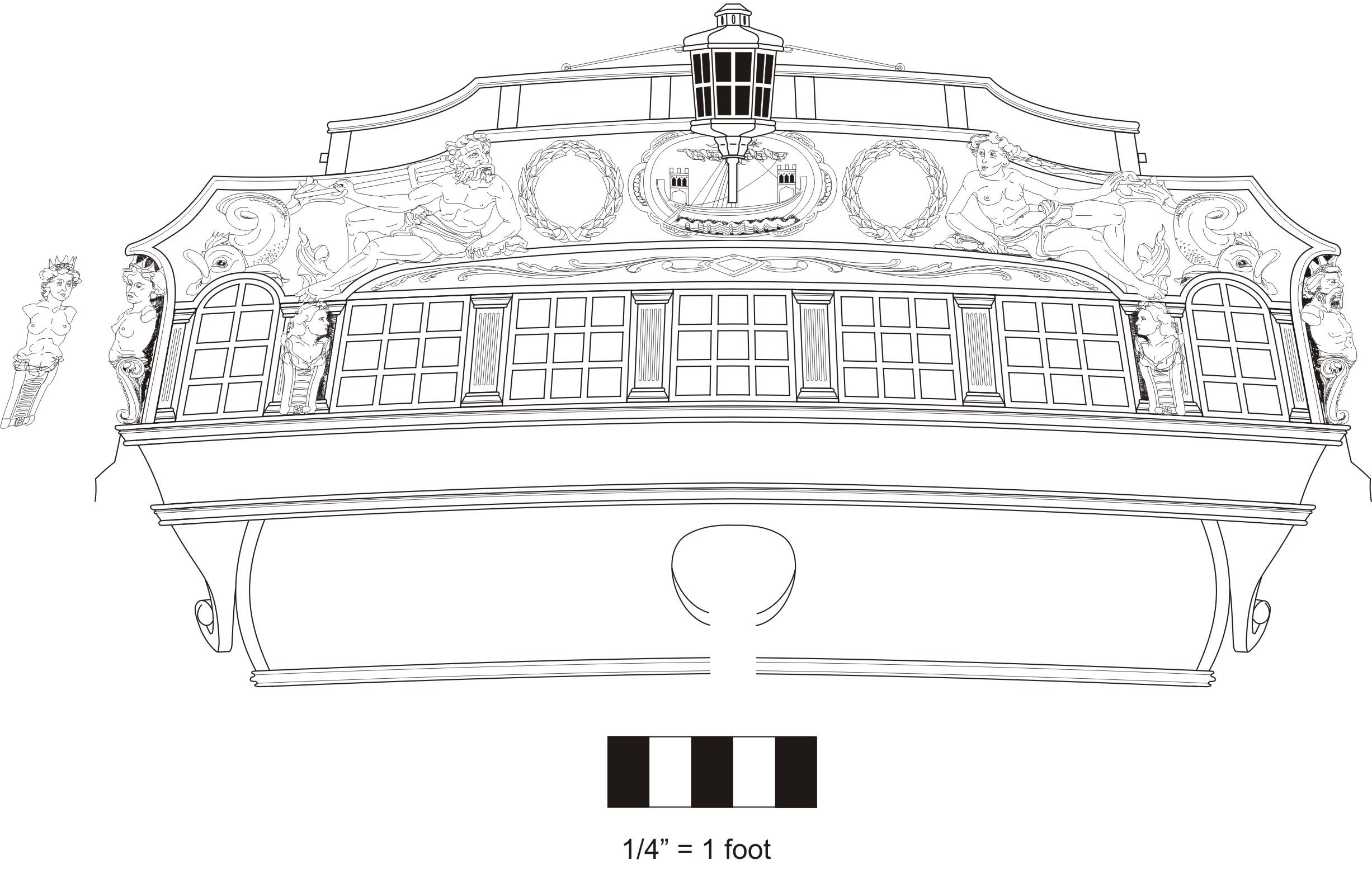
scrubbyj427 Posted March 31, 2020 #649 Posted March 31, 2020 Chuck, just out of curiosity, why were the two aft quarter galley windows blacked out? Did all vessels of the time do this? Thanks, JJ FrankWouts 1 Current Builds: HMS Winchelsea 1764 1:48 - 5th rate 32 gun frigate (on hold for now) HMS Portland 1770 Prototype 1:48 - 4th rate 50 gun ship
Chuck Posted March 31, 2020 Author #650 Posted March 31, 2020 I believe so. I believe it was the exception to have them as actual windows. Most were false. I am not entirely sure why but my guess is probably to make it stronger. I could be wrong. Chuck FrankWouts 1 Chuck Passaro - MSW Admin Sloop Speedwell - POF scratch Block Island Boat - POF scratch HMS Winchelsea - POB scratch build HM Cutter Cheerful - POB scratch build Royal Barge - POF scratch Medway Longboat- POF Scratch SYREN SHIP MODEL COMPANY
scrubbyj427 Posted March 31, 2020 #651 Posted March 31, 2020 Ahh ok. The temptation is definitely there to make them see through to show detail. JJ FrankWouts 1 Current Builds: HMS Winchelsea 1764 1:48 - 5th rate 32 gun frigate (on hold for now) HMS Portland 1770 Prototype 1:48 - 4th rate 50 gun ship
MEDDO Posted March 31, 2020 #652 Posted March 31, 2020 I just kind of figured that those windows were all blacked out mostly because glass was pretty expensive back then and basically all it would be doing is putting a window behind you when you were using the toilet it’s not like you were looking out at a nice view behind you while taking care of business. Maybe in very large for second or third rates it would be different. I don’t know I’ve never seen a definitive reason either Jorge Diaz O and FrankWouts 2 Michael Shipwrights of Ohio Current Build: ... Completed Builds: Queen Anne Barge - Syren, Pinnace - MS, Halifax 1768 - LSS, Murrelet - Pygmy, Swift 1805 - AL
Chuck Posted April 5, 2020 Author #653 Posted April 5, 2020 Feeling a little burnt out making rope and blocks....will be back at that tomorrow!!! So today was a good day to start chapter 4.... This is where we start working inboard and get the deck planked and the bulwarks planked. To start, We need to plank the sub decks. Those are those areas that wont be seen and you are just creating a platform for the ladders. Nothing will be seen down there so no need to start constructing coamings and other stuff. Just neatly plank it with 1/4" x 3/64" planking strips. Dont forget to run a pencil over one edge to simulate the caulking. I started by running one strip down the center line and then I worked my way outward. Picture is below....do this for both platforms. In that same photo you can also see a laser cut piece glued to both sides of the bulkheads. You can see numbers as reference for the bulkheads it sits between. This starts the process of framing out the box so we can build the coamings. You can also see that those pieces have laser etched mortises for the frames which will be added next. Next up, I added the beams...this is the center platform in the waist. The three partial "deck" beams were sanded free of laser char. the beams are also laser etched with mortises to accept the carlings. The carlings were cut from 1/8" x 1/8" cedar strips. Please note that these photos just show a dry fit of all of these pieces. The laser cutter does a great job of etching the deep mortises for the carlings. Although this is the case, you should still square them up a bit and clean up the corners for best results. I did this by scraping the mortises with a sharp #11 blade. You wont have to use a chisel at all. All these mortises need is a bit of scraping!!! The carlings were cut to length carefully for a nice snug fit. Dont cut them long and then force them into the mortises. This will force your beams apart and give you problems later on. Take your time with these. You can adjust those deck beams "port-to-starboard" so the carlings sit correctly in the mortises. Make sure they are parallel to the center line of the deck and to each other. Your coaming will be built over this. This is just a dry fit so I could tweak them all. You can see all the reference letters I placed on top of each piece so I dont mix them up when I disassemble it. Then it was glued in place permanently and the top sanded and faired. Here is an image of the aft platform and its beams and framing completed. This is done exactly the same way as the one in the waist. The only difference is this has a central beam which has laser etched mortises on both sides. This should give you a good idea on how I plan to create the quarter deck beams and framing. The ability to laser etch mortises for any ledges and carlings is a huge game changer. This technique will have many many applications!!! You can see how it is possible to get nice tight joints. And now you dont have to worry about measuring accurately for their placement on the beam and using a chisel to make mortises from scratch. gjdale, Nunnehi (Don), ir3 and 38 others 41 Chuck Passaro - MSW Admin Sloop Speedwell - POF scratch Block Island Boat - POF scratch HMS Winchelsea - POB scratch build HM Cutter Cheerful - POB scratch build Royal Barge - POF scratch Medway Longboat- POF Scratch SYREN SHIP MODEL COMPANY
captainscott Posted April 11, 2020 #654 Posted April 11, 2020 This has to be the most impressive tutorial I have ever read. Thank you for explaining everything in such detail. I learned plenty from just reading through. What a beautiful build. FrankWouts 1 Working on : Shrimpboat Built: Bounty Launch
Chuck Posted April 11, 2020 Author #655 Posted April 11, 2020 Thank you very much. No laser etched decking!!!!! I absolutely despise tthem with all the planks laser etched. It makes your entire model look kit-like when finished. A model this size makes it nearly impossible to do anyway. So yes we will be fully planking ours deck with wood strips. But you will lots of help and reference lines to help you out. The false decking.... The false deck is now glued in position. There are six large sheets. They are 1/32" thick. These false deck segments have many laser reference lines. So everyone must be super careful, make sure all of the reference lines match up when positioning these. Most important, make sure the center line between these is actually on the center line. This will ensure all of your fittings and coaming run down the center of the deck as they should. There is a trick that you may find helpful. But first, you should absolutely do a dry run with all six sheets in position. Because everyone will fair the inside of the hull differently, these may be loose or tight on your model. You may need to sand and trim the outside edges to get them to fit properly. Dont worry about having a small gap along the bulwarks. It is more important that you line up all of the reference lines and get the center running down the center..... A good trick is to dry fit all six in position. Then drill a few holes through the false deck sheets and into a few bulkheads. If you insert a few pins in these you can use them as registration pins when you glue each segment in position permanently. Drill all the registration pins for all six segments as you have them all in position. I hope that makes sense. You can see how there are two openings in that photo above for the two coamings which will be open companionways. I decided to go ahead and make these two coamings now. Although I didnt glue them in position. They may get damaged while I plank the bulwarks so I just skipped ahead a bit to procrastinate a bit before planking. You can see how they fit in those openings and on top of the framing you made for them. All of the coaming pieces are laser cut. They go together quickly. They have the camber build into them which is a good thing. You will also get a small right angle jig. You will actually get two of these. There use depends on which coamings you are building. These first two coamings use the 5/64" thick jig. All others will use a thinner jig. You can use the outside of the jig to get a right angle on the coamings. You dont want skewed coamings. I usually build two pieces as shown below and set them aside. Then I take the remining two sides and repeat the process. To finish the coaming I then glue these two pieces together to complete the coaming. This particular coaming is the aft one pictured on deck (J2). I show this one because it has an additional timber that separates it into two parts. There are notches for these and it was easy to just slip it right in and the coaming remains squared up. Then I finish it off by sanding all of the laser char off. I havent applied any finish yet. Once you have the initial coaming completed, you must add thin strips along the inside edges to form the rabbet. This is what the gratings will sit on. These are 1/32" x 3/16" strips. Everything is yellow cedar. Lastly....you must round off the four corners above the deck planking (which we have yet to do). That is why these two coamings (J1 and J2) use the thicker 5/64" jig. Simply use it to round off the corners down to the jig when the coaming is set against it. You can just use a #11 blade to make some straight cuts and then round it off with some sandpaper. You can see the finished corner on the left side. All four will end up looking like that. Only a small amount needs to be sliced off. Dont cut too much of the corner away!!! One last thing.....as with everything else. You can paint these coamings black like the contemporary model or leave them natural. Its up to you. I havent decided yet but am leaning towards painting them black. On such a big model like this I think it will break things up. Otherwise it will look all to similar down the middle of the deck. You guys have any preferences??? The HMS Amazon (contemp model) has a different painted look below....the qdeck is fully painted black while the gun deck only has the sides of the coamings painted black. Which is odd. Finally.....you have the Minerva contemp model....They are all natural on the gun deck and all painted black on the quarter deck. So many choices. You could also just leave them all natural. As you can see I like to really examine and study many contemporary models and that usually just leads to more difficulty in choosing which way to go!!! Tigersteve, RichardG, G.L. and 22 others 25 Chuck Passaro - MSW Admin Sloop Speedwell - POF scratch Block Island Boat - POF scratch HMS Winchelsea - POB scratch build HM Cutter Cheerful - POB scratch build Royal Barge - POF scratch Medway Longboat- POF Scratch SYREN SHIP MODEL COMPANY
druxey Posted April 11, 2020 #656 Posted April 11, 2020 On the question of dummy lights (blank windows): The outer lights of the stern galleries were usually blank. The reason for this was that just forward of these dummies in the quarter galleries were the 'seats of office', or heads. FrankWouts, MEDDO, dvm27 and 1 other 4 Be sure to sign up for an epic Nelson/Trafalgar project if you would like to see it made into a TV series http://trafalgar.tv
scrubbyj427 Posted April 12, 2020 #657 Posted April 12, 2020 I really like how the Amazon is finished, it has a nice weathered look. Not sure if this is from age or intended but I makes it look real. A lot of the models at the naval academy appear like this. I also like Minervas finish..I can’t decide either, on which direction to take mine! JJ FrankWouts 1 Current Builds: HMS Winchelsea 1764 1:48 - 5th rate 32 gun frigate (on hold for now) HMS Portland 1770 Prototype 1:48 - 4th rate 50 gun ship
Beckmann Posted April 12, 2020 #658 Posted April 12, 2020 Maybe the coamings on the quarter deck were painted black to give them a better protection, because they were more exposed to the weather. This might have not been necessary in the waist. FrankWouts and Hubac's Historian 2
Chuck Posted April 12, 2020 Author #659 Posted April 12, 2020 Here is a look at the coaming painted black with a grating in position. But these will be removed when I start planking the bulwarks. But first some pre-planking prep work. Before I can start planking the bulkwarks, I need to add some filler timbers (laser cut) where the hawse holes will be drilled. Then they were faired inboard. In addition, a 1/4" x 3/64" strip was glued down the stem so-to-speak. Shape the top round where the bowsprit hole is neatly. Keep this neat and round. The bulwark planking will abut the side of this vertical strip. And finally the bulwark planking can begin. The two lower strakes are the first layer of spirketting. The top of the spriketing should run even with the lower edge of the port openings. So you need to do some math. The distance from the false deck to the bottom edge of the ports can vary from model to model. It depends on so much....where you placed your sills....whether or not they are flat or angled inboard....etc. So you want to run two strakes for the spirketting 3/64" thick. On my model I used one 7/32" wide strake first and then the second upper strake was 1/4" wide. This combination was the perfect width in my case. Although you will inevitable find some ports that are slightly high or slightly low. You will need to adjust these should that arise....but most of mine lined up pretty good. You will be adding a second 1/32" thick layer to the spirketting later on. I did not simulate the seams with pencil because the bulwarks will be painted red. Except of course for in the captains cabin aft. There is a double line on the false deck showing where the captain cabin starts. So aft of this reference I did in fact simulate the tarred lines. So this photo shows the two strakes of the spirketting and how they run true with the bottom of the ports. I also added the inboard side of the fixed blocks. You can see one in the photo. I used some wire pushed through the sheave holes from outboard to help line them up. Let me know if you have any questions. Jack12477, Nunnehi (Don), JpR62 and 30 others 33 Chuck Passaro - MSW Admin Sloop Speedwell - POF scratch Block Island Boat - POF scratch HMS Winchelsea - POB scratch build HM Cutter Cheerful - POB scratch build Royal Barge - POF scratch Medway Longboat- POF Scratch SYREN SHIP MODEL COMPANY
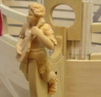
scrubbyj427 Posted April 13, 2020 #660 Posted April 13, 2020 Looks really good Chuck, looking forward to chapter 4, chapter three as well. Lol. does the 1/48 figure come with chapter 4? I could use a project manager on my Winnie. JJ FrankWouts 1 Current Builds: HMS Winchelsea 1764 1:48 - 5th rate 32 gun frigate (on hold for now) HMS Portland 1770 Prototype 1:48 - 4th rate 50 gun ship

Recommended Posts