
James H
-
Posts
5,613 -
Joined
-
Last visited
Content Type
Profiles
Forums
Gallery
Events
Posts posted by James H
-
-
Can't wait for the photos.
Those internals you added sound interesting.
-
Still a handy enough size too, at 2ft long. Looking forward to seeing you build this.
- paulsutcliffe, Elijah, bruce d and 1 other
-
 4
4
-
I'm absolutely stunned by this work. I really wish I could do this sort of thing. At least I can dream.
- KentM, mtaylor and Bluto 1790
-
3
-
Hi all,
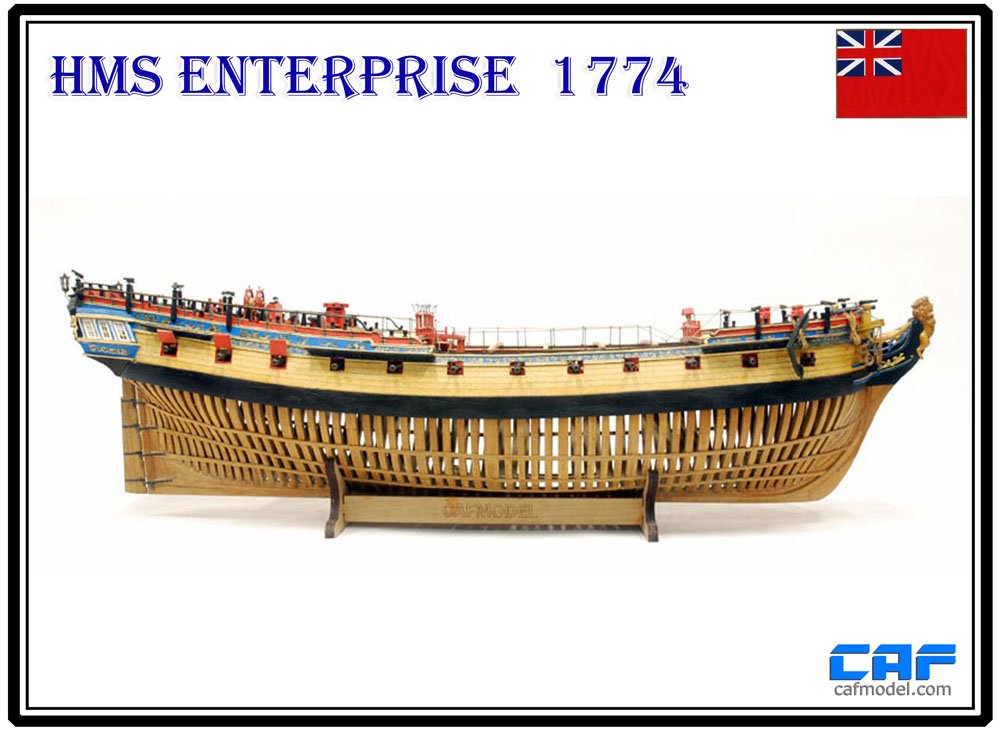
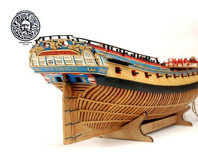
Model Ship World would very much like to announce CAFModel as a site sponsor and supporter, and also of the NRG. This has taken some real work, but it's great to see CAFModel here amongst our other sponsors, and it will be wonderful to see their creations built as logs here at MSW. We have added the CAF banner to the website, complete with a link to their own site, and included it in this post also.
I will also start to bring you a series of in-box reviews of CAF kits here too, starting very soon. Dont forget to check out the CAF website for kits of all kinds, along with fittings and carvings.Note from Admin: CAF now meets all criteria as a legitimate MFG of ship model kits. They have stopped producing all kits based on source material they did not have the rights to use, mainly from Ancre. There current kits available on their website including the Enterprise, are perfectly fine and original works not taken without consent from other authors, designers and mfg's.
We are currently helping Tom at CAF to acquire the proper rights through an agreement with Ancre to make any Ancre kits legally allowable. Until such time all CAF Ancre inspired kits are not allowed on MSW. But we are hopeful they soon will be. CAF has stopped mfg them and selling these Ancre related kits voluntarily after admitting he copied the material from Ancre without consent. Negotiations are currently underway to rectify that situation.


- mtaylor, Duanelaker, JpR62 and 24 others
-
27
-
-
2 minutes ago, VTHokiEE said:
I have no experience with this specific one but agesofsail.com has at least this one: https://www.agesofsail.com/ecommerce/hobby-tools/amati-tools/am7399-amati-new-nail-nailer.html
That's the one I have.
-
20 minutes ago, Emmet said:
Where do you get the pin pusher? I have the pin vise but it will not drill into the plywood frames.
Depends where you are. If UK, then try https://www.cornwallmodelboats.co.uk/acatalog/hammers_pin_pushers.html
Outside of UK, not sure. Maybe Ages of Sail do them?
-
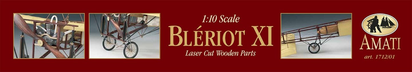
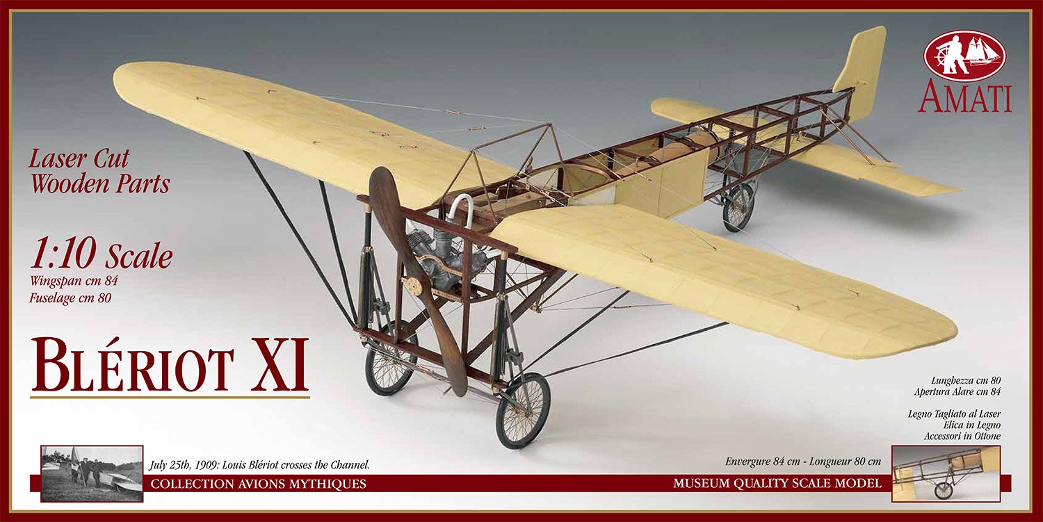
1:10 Blériot XI
Amati Model
Catalogue # 1712/01
Available from Amati for €284.43
“England’s isolation has ended once for all!”, so was written in an English newspaper, on the day after Louis Blériot flew across the English Channel from France. The French aviation pioneer, in his modified type XI monoplane, took off from Les Baraques near Calais at 4.41am on July 25th 1909, and landed at 5.17am in Northfall Meadow, near Dover. The Bleriot XI made its debut at the Paris Salon de d’ Automobile et de l’ Aeronatique in December 1908, along with two other Bleriot planes; the type IX and the type X. In October 1908 the London Daily Mail had offered a prize of £1,000 to the first aviator to cross the Channel in either direction. Bleriot’s exploit was proceeded by the unsuccessful attempt of another aviation pioneer, namely Hubert Latham.
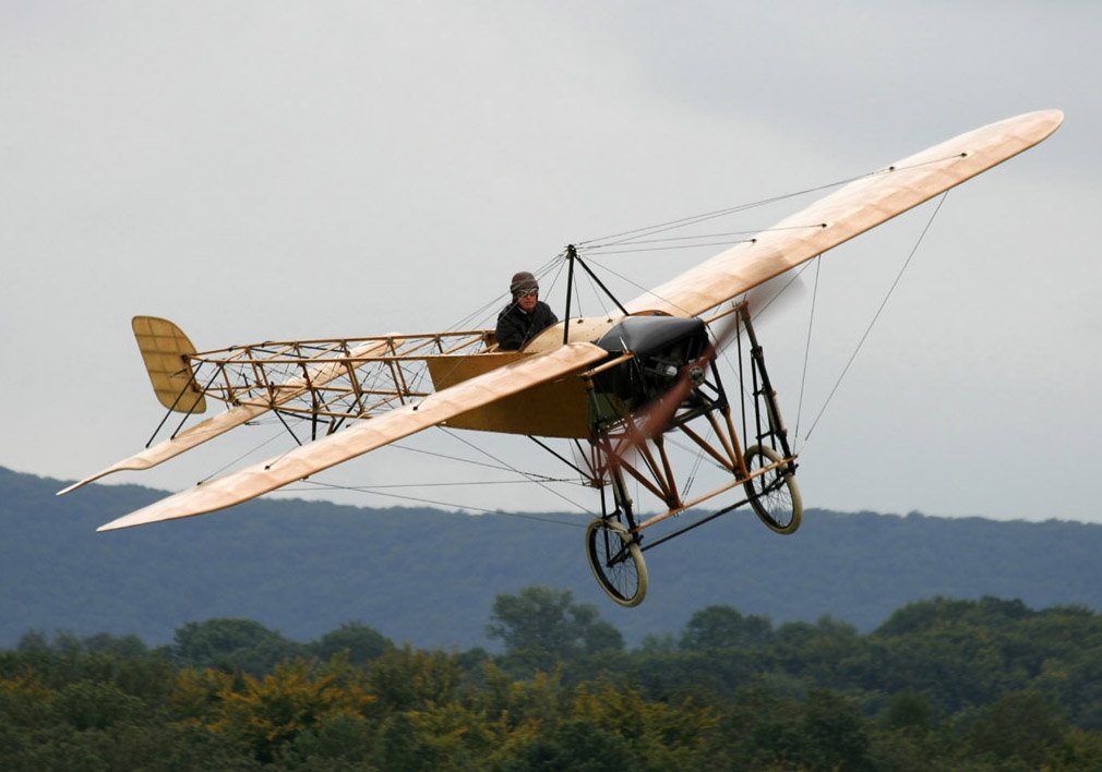
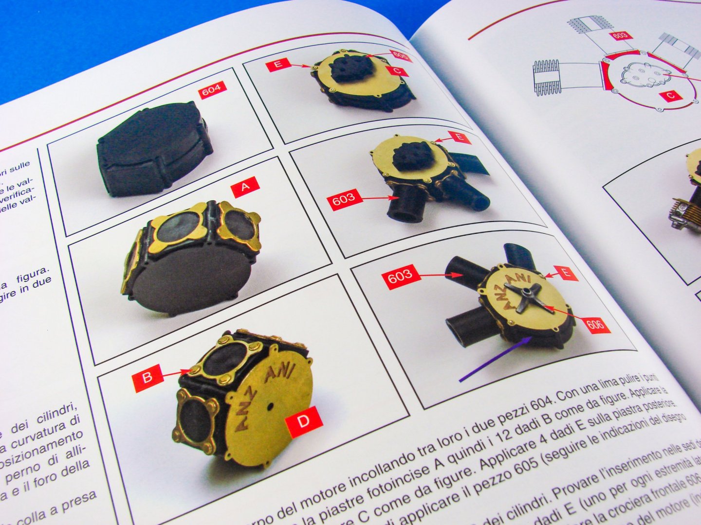
Designed by Louis Blériot and Raymond Saulnier, the Bleriot XI was a light, sleek monoplane built using oak and poplar wood with cloth-covered wings and was powered by the very reliable but simple Anzani 3-cylinder 25 HP engine. The plane's sporting achievements, robustness, functionality and piloting ease contributed greatly to its commercial success, and it was actually the first aircraft in the history of flight to be used in war, when Italian Capitano Piazza piloted a Bleriot during the Libyan campaign between 1911 and 1912.
Sourced from Amati and WikipediaThe kit
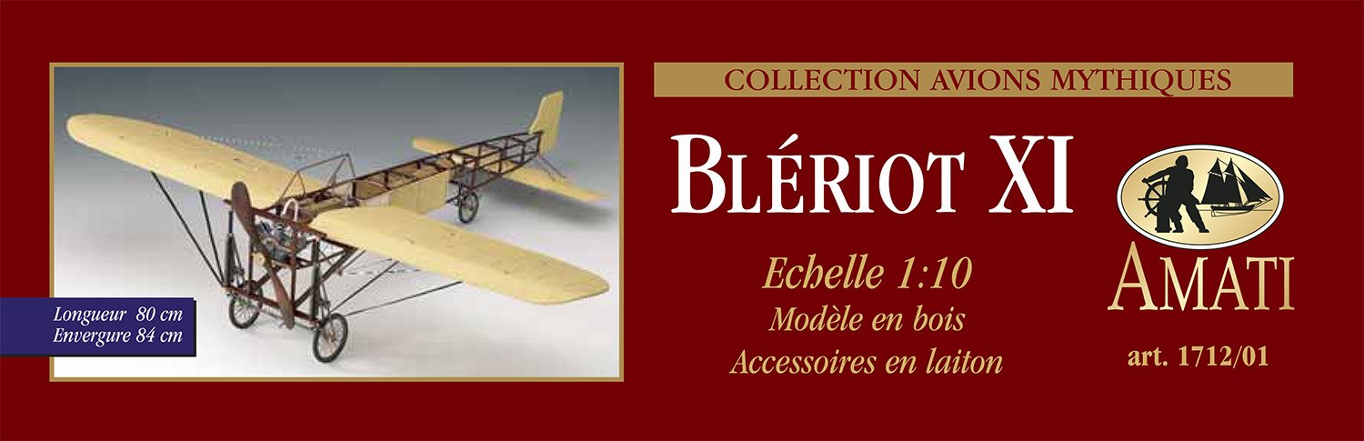
This kit is certainly not a new release, but it is one for which you can’t really find an unboxing/summary/review. After talking with Amati, we thought we’d redress that issue and bring you an article on this kit, in the style of our regular ship reviews. As you would guess from a 1:10 aeroplane, the box for the Blériot isn’t too small, with it taking up a reasonable chunk of my worktop real estate. Whilst being fairly average in weight, it’s a little top heavy with the parts packing, so careful if you prop it up against a wall like I originally did! Amati always ship in beautiful boxes, and this sturdy and glossy crate is no exception, with a very nice photo of a finished Blériot model on the lid, along with a period photo and detail image. You’ll also get a good idea of the size of this project when completed, with the given sizes being:- Wingspan: 84cm
- Fuselage length: 80cm
A note of course that the timber parts within are all laser cut, as we’ve come to expect from this and many contemporary manufacturers. The box sides contain more imagery of the finished model at various angles.


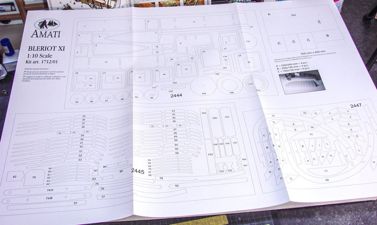
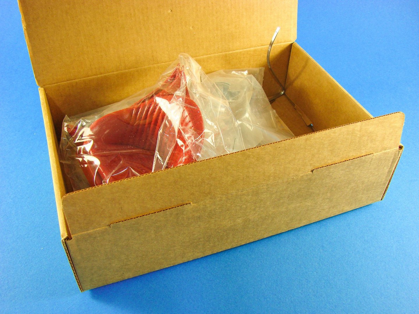
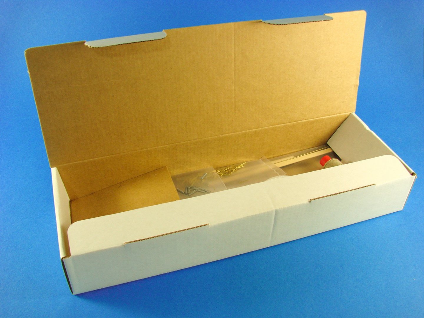
Lifting the lid, you can see why the box is top heavy. Most of the parts are sitting on a card plinth within the base of the box, designed to stop the various elements rolling around within. Right on top is a large and thick cellophane sleeve containing all of the laser-cut wooden sheets, plus the two sheets of plans. We’ll look at the latter in a short while.
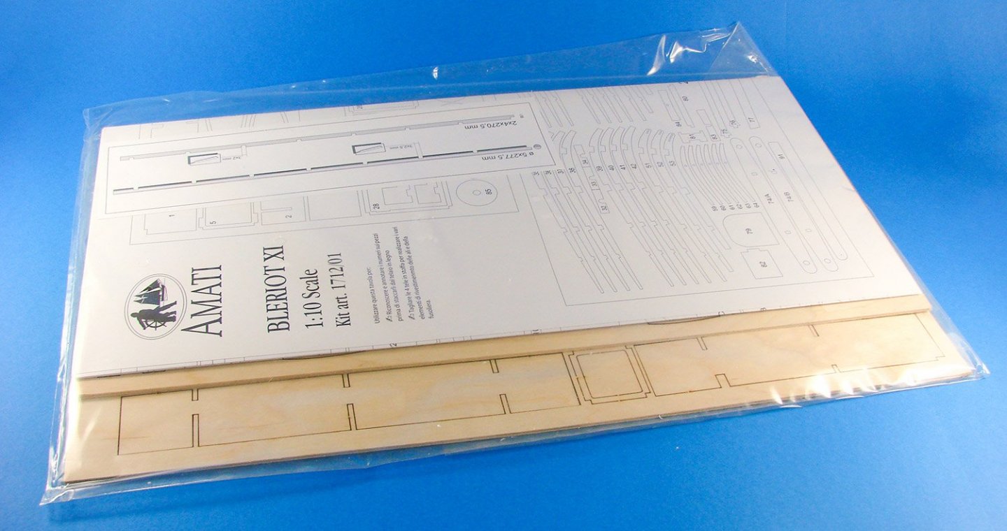
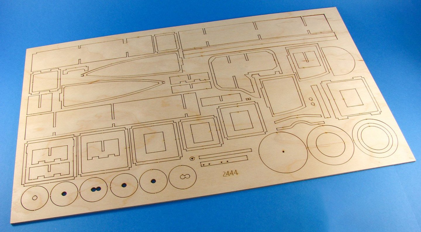
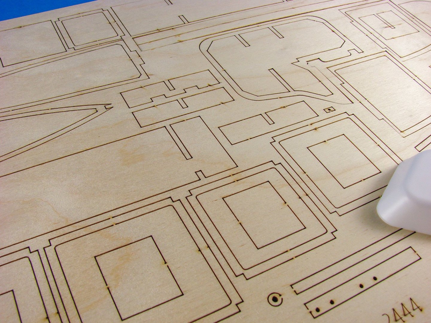
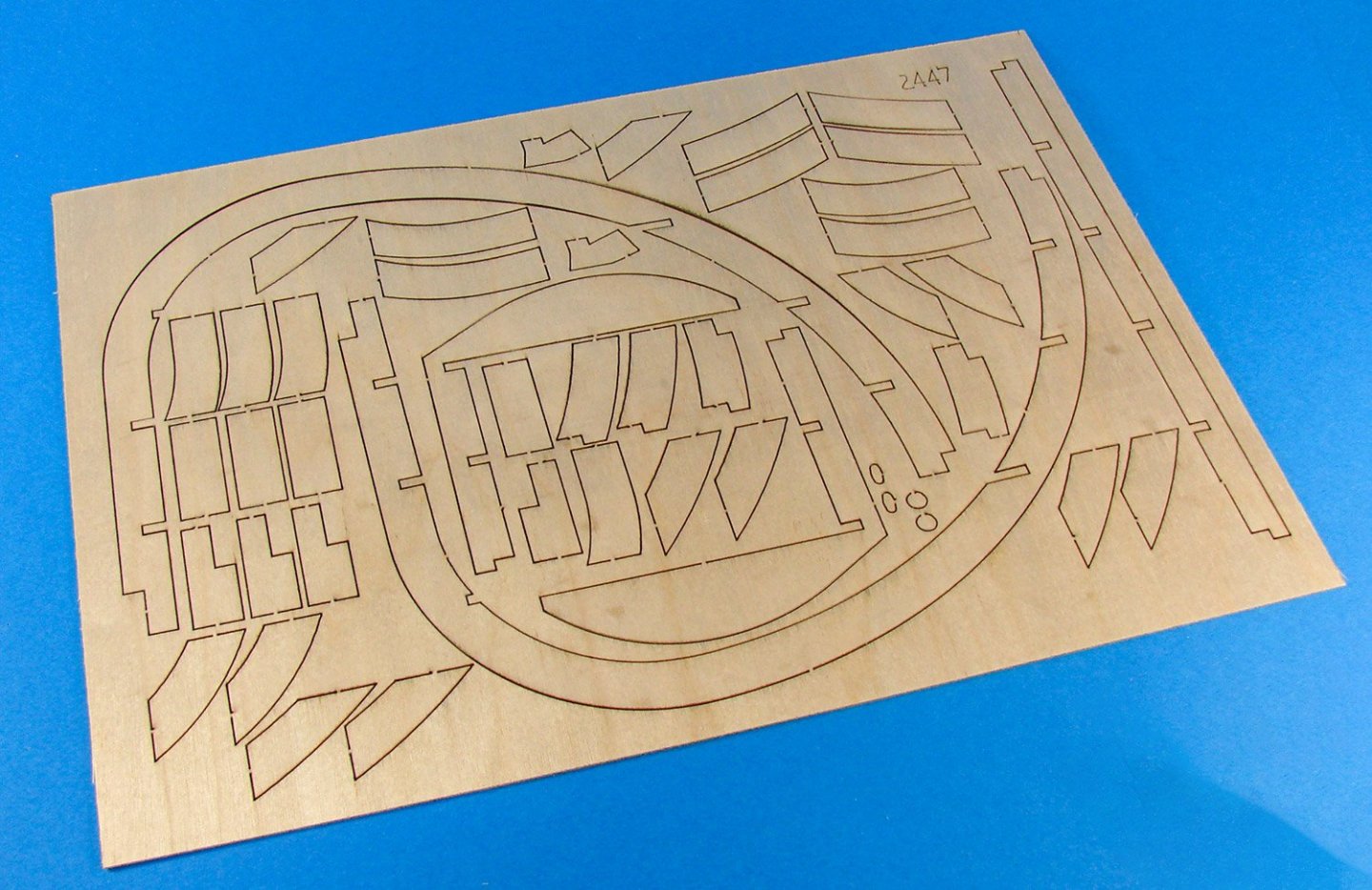
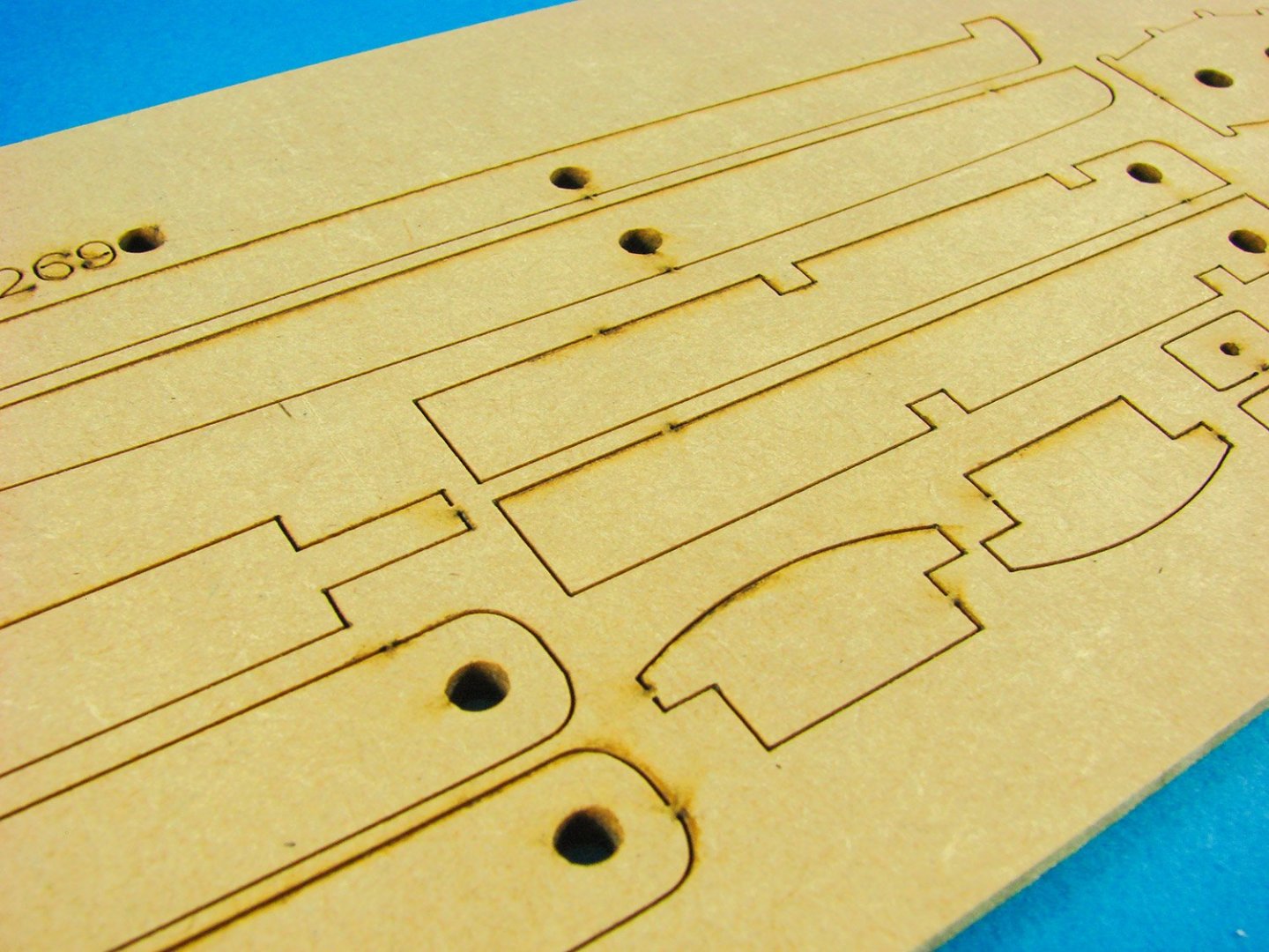
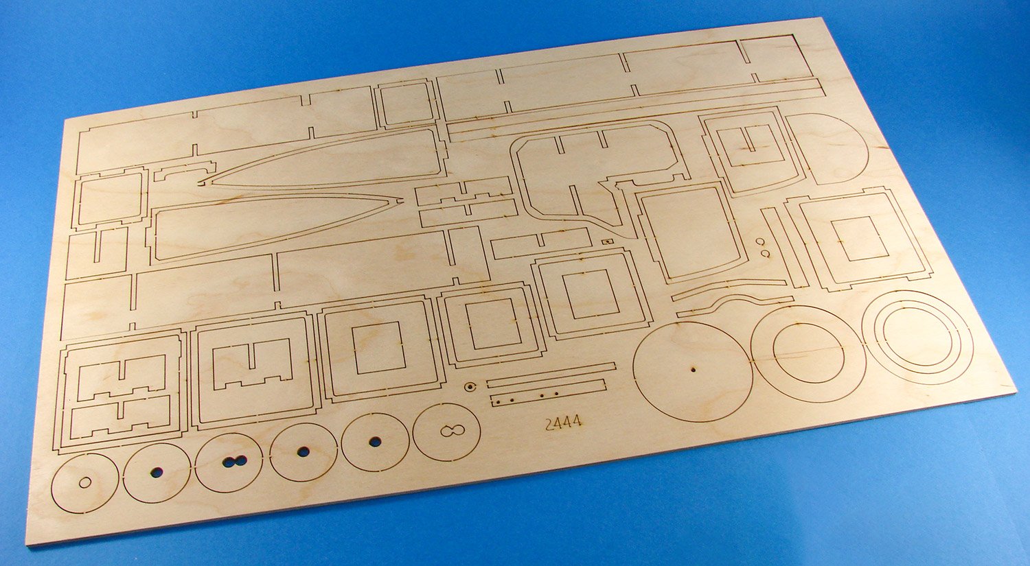
The fist 3mm thick ply sheet contains parts for the fuselage and tail frames, plus some jigs for creating those spoked wheels. Jig parts are also included for creating fuselage sections, ensuring that the various frames etc. are correctly aligned. As you can see from the sheet, none of the parts are numbered, as you wouldn’t want that with a model whose frames are very visible timber. These can be checked off against the supplied parts sheet. Laser cutting is also excellent with very minimal scorching. Being quite light, you will be advised to stain the frames when the time is appropriate.
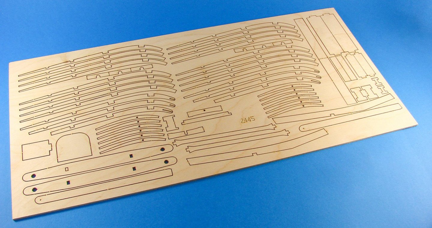
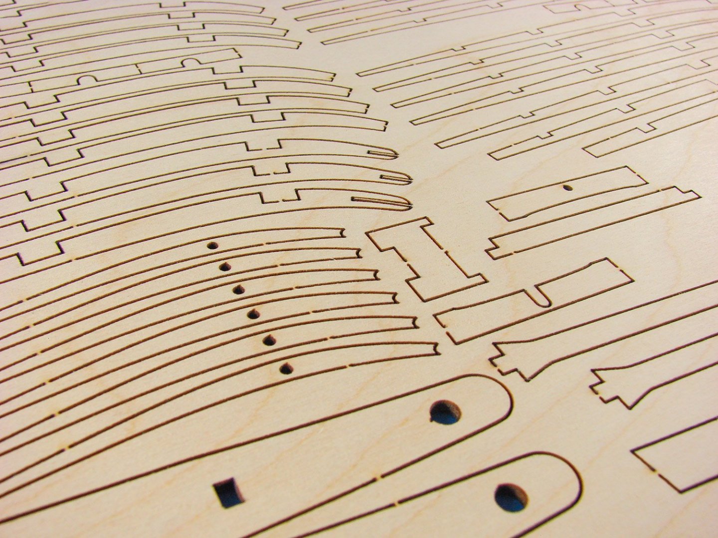
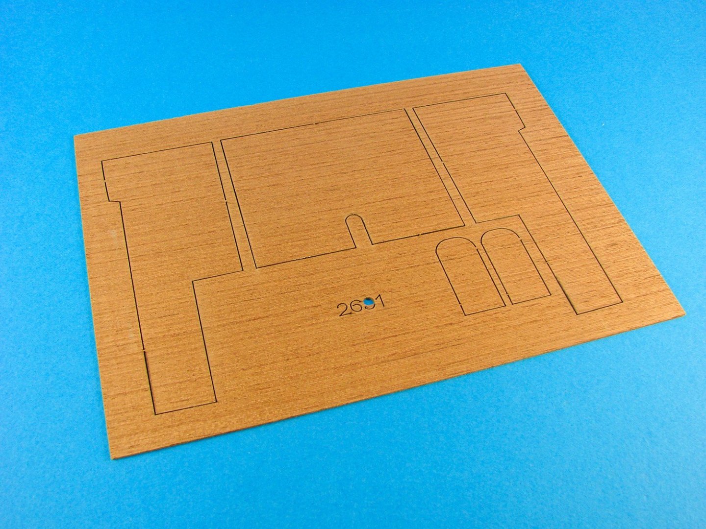
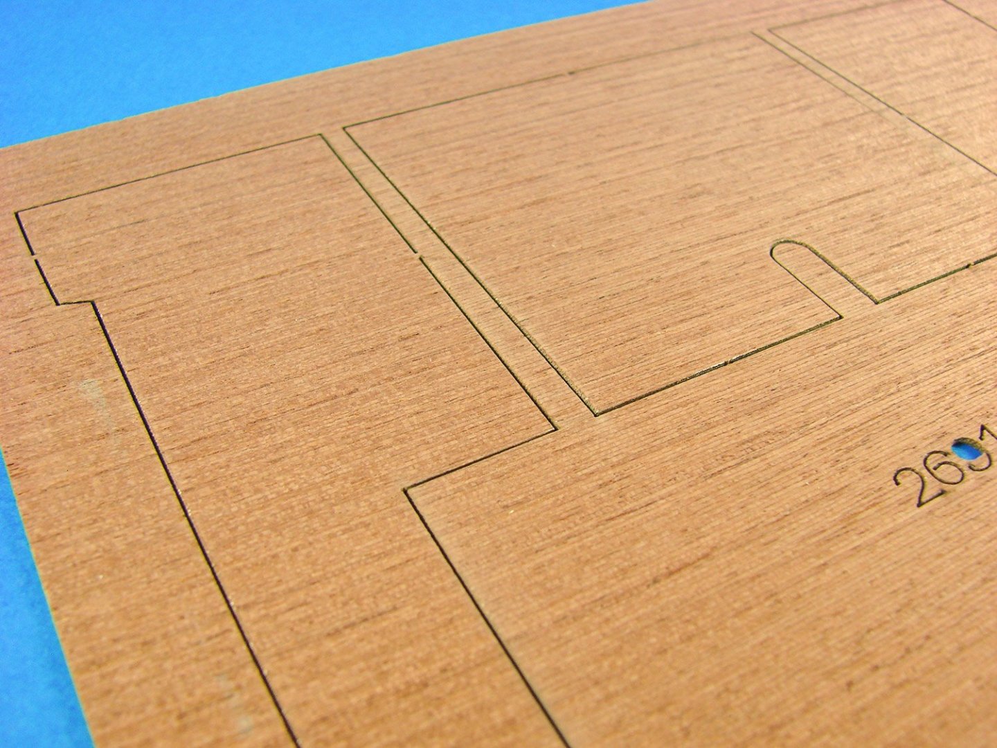
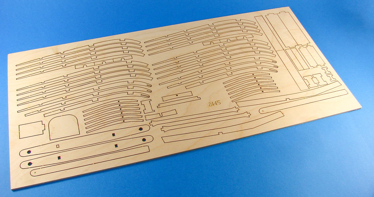
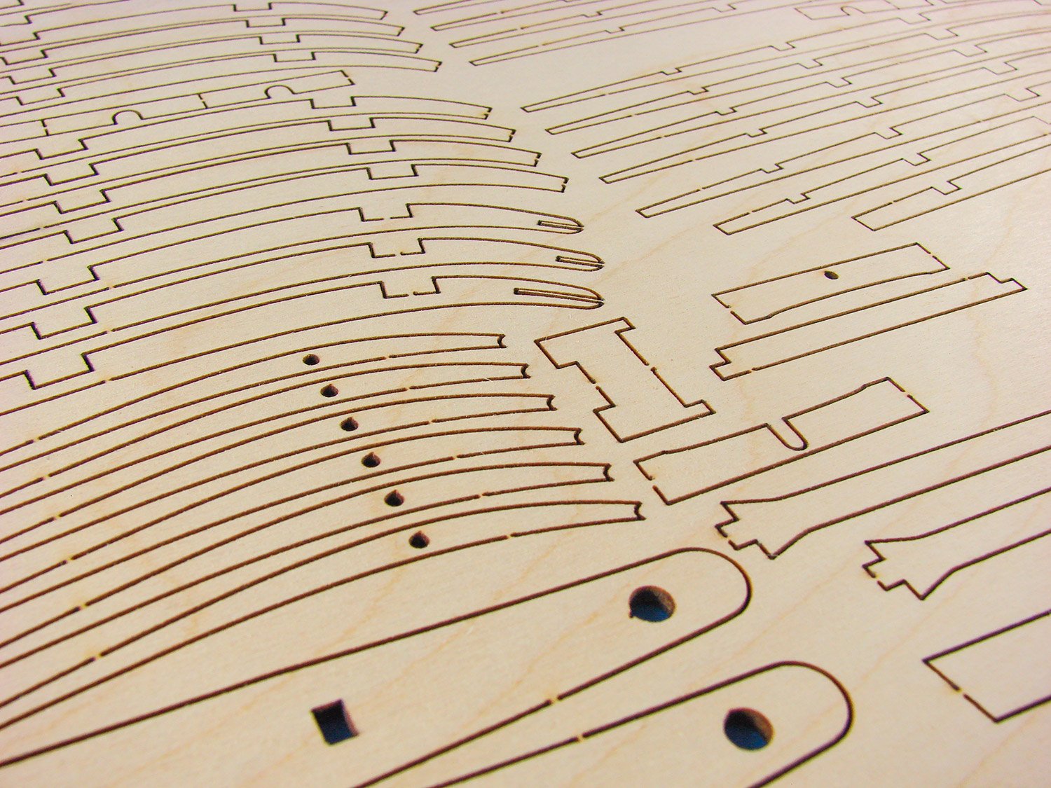
This second sheet, again in 3mm ply, contains mostly parts for creating the wings and horizontal tailplane. Here you can see the various ribs with their notches for wing spars etc.
We have another ply sheet here, but this time in a much thinner 1mm material. The larger curved parts here are the enormous wingtips, with the thin material designed to be able to create the curved underside of the thin wing. The smaller parts are mostly infills, which will then sit on top of the moulded wingtip and pack its thickness up to a more realistic 2mm.
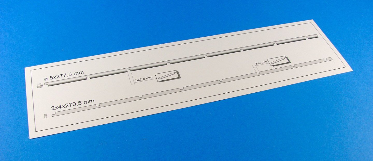
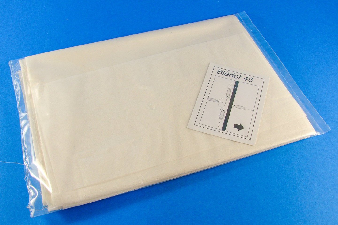
This small slip was packed into the sleeve, and it depicts the cut-outs needed in both dowel and strip for the main fixed tailplane section. This is supplied at full size for easy reference.
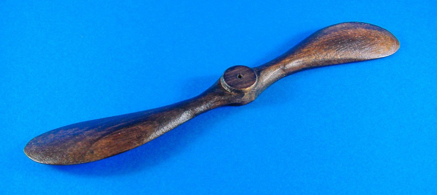
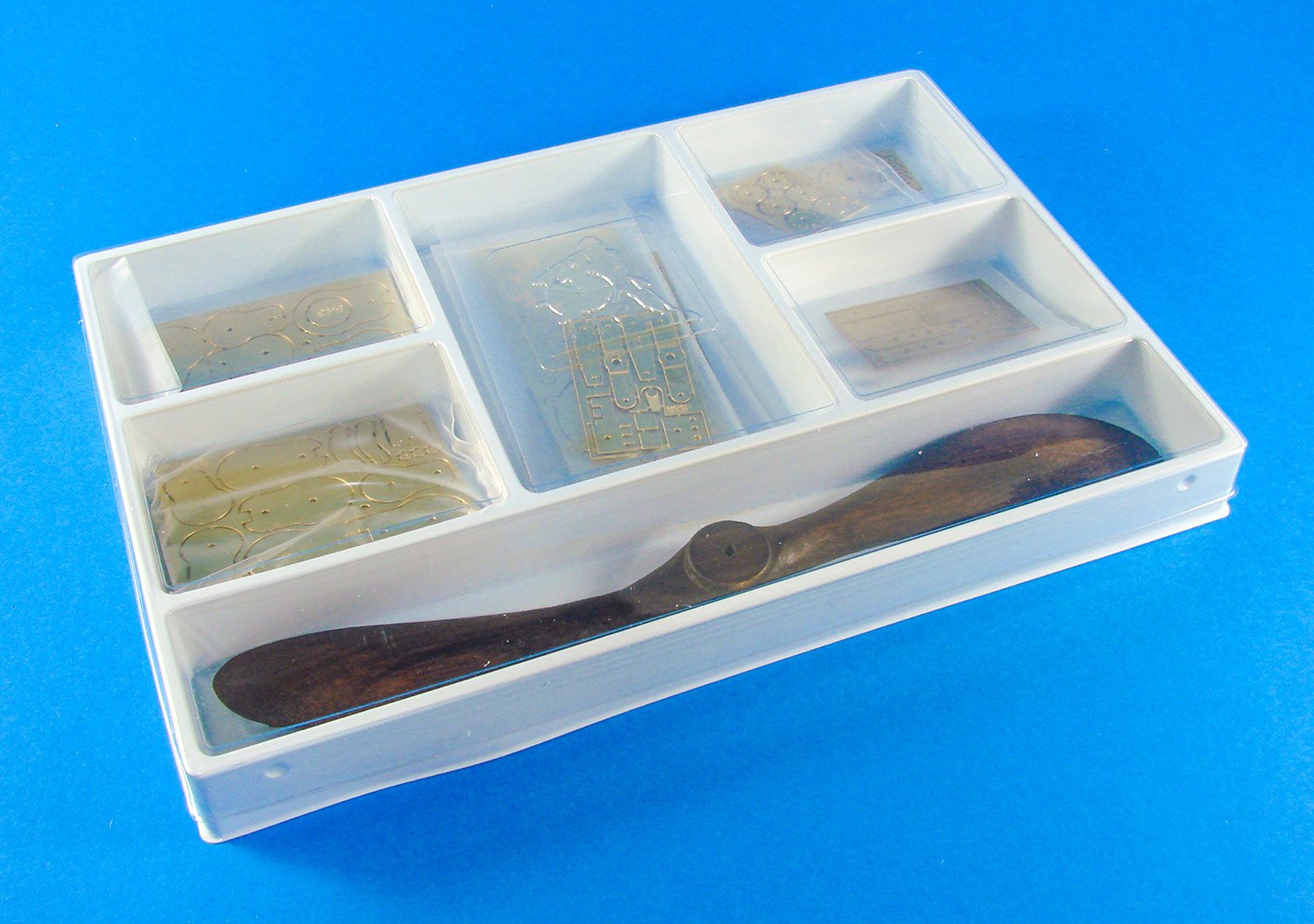
There are three trays of components in this release. This first tray is the most obvious as it contains the large propeller/airscrew. These are standard Amati trays and the packets and parts inside are held in situ by a clear plastic lid.

The prop/airscrew is finished in a dark varnish. Not sure how accurate this is, and I may consider stripping this and making it look laminated, along with a lighter varnish. The prop hub is a series of PE parts which need to be fitted.
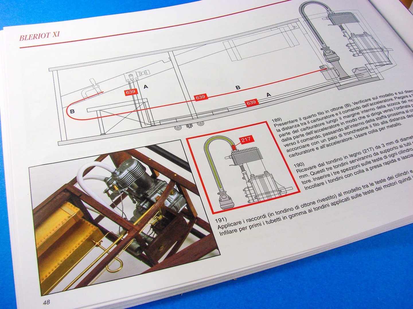
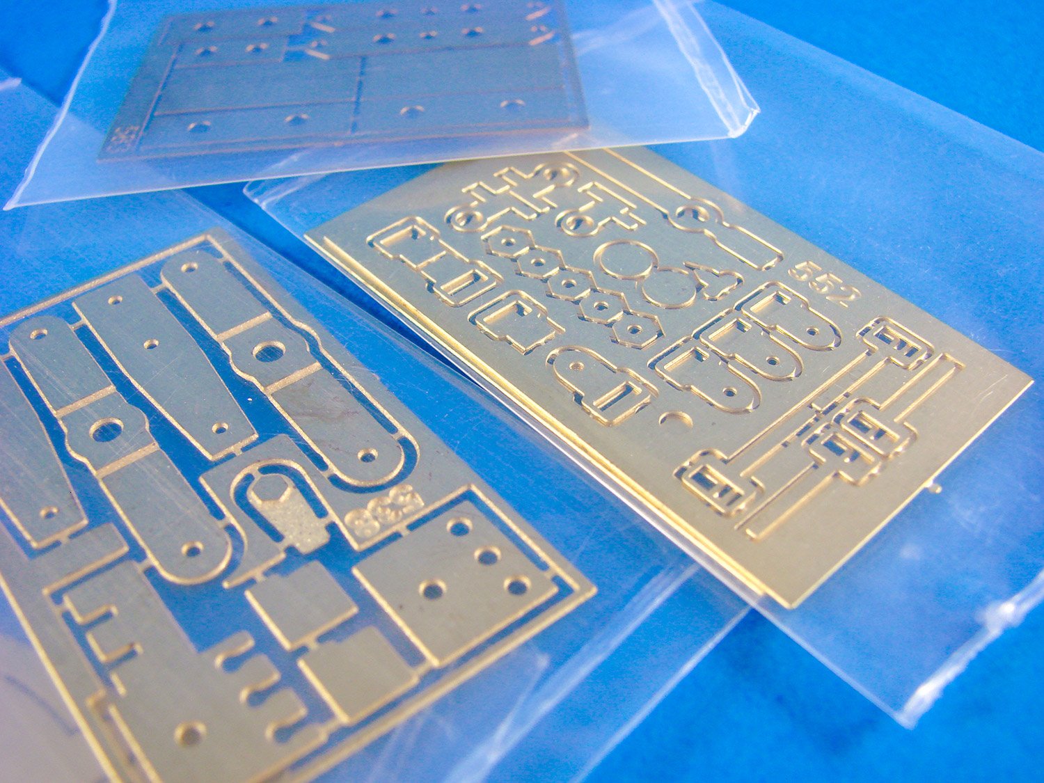
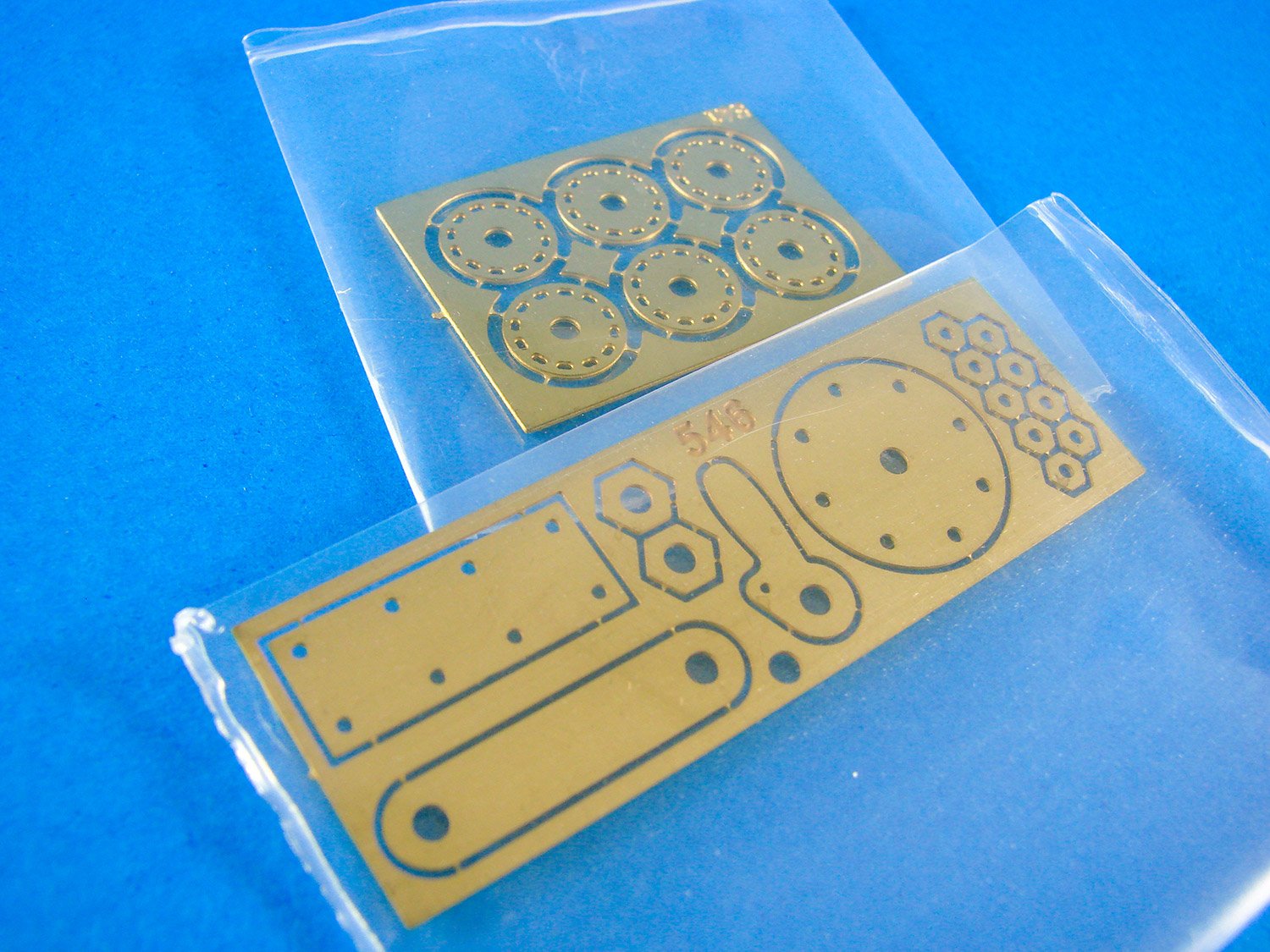
We now have several frets of photo-etch, all individually packed in thick plastic sleeves. All PE is of different gauges, but the connection tabs are quite small, so it won’t take long to remove them from the frets. A small file can then we used to smooth off the connection points. You will note parts here for the engine and engine framework etc.
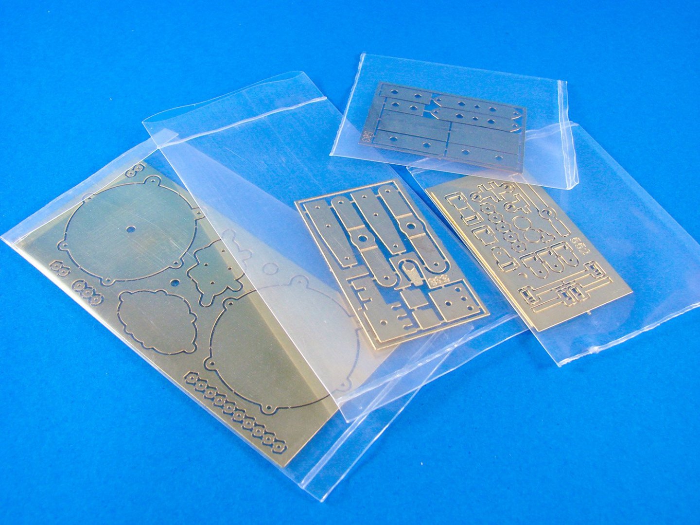


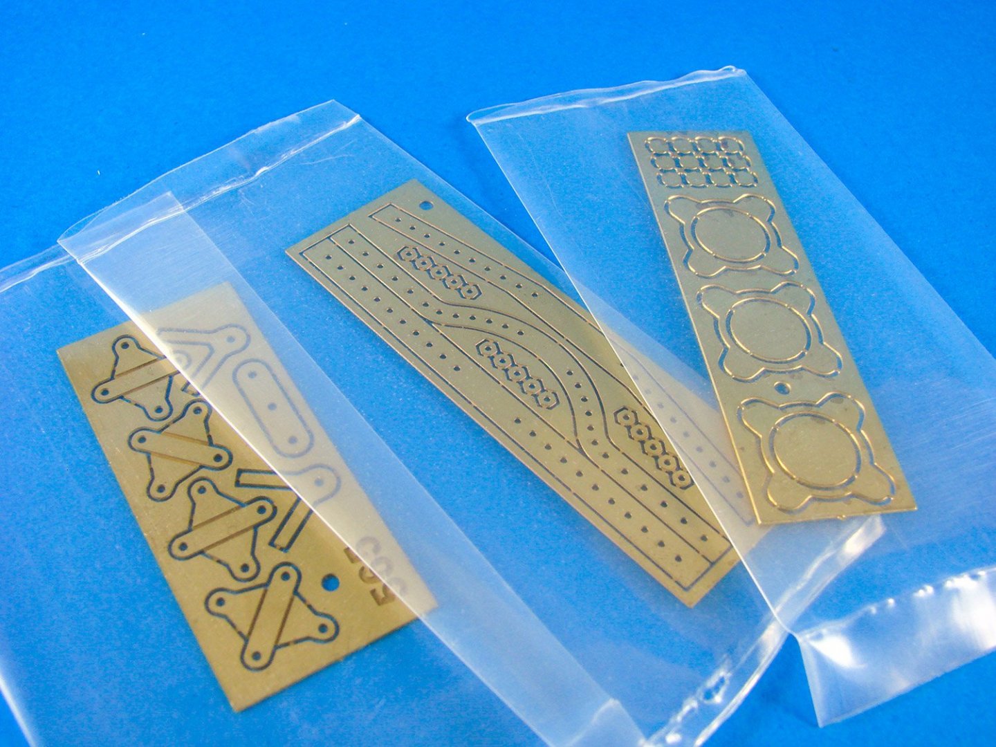
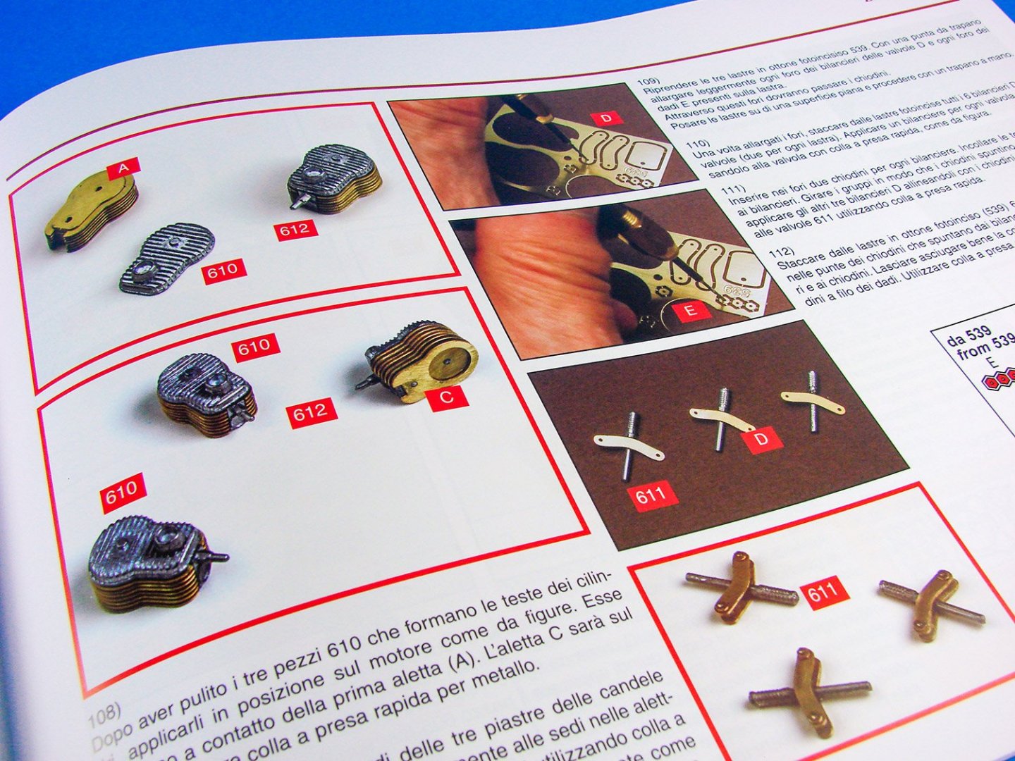
These are the cylinders, comprised of parts which stack upon one another, creating a cooling-fin effect. That should look quite nice when done, and beats using plastic where you’d need to remove an awkward seam.
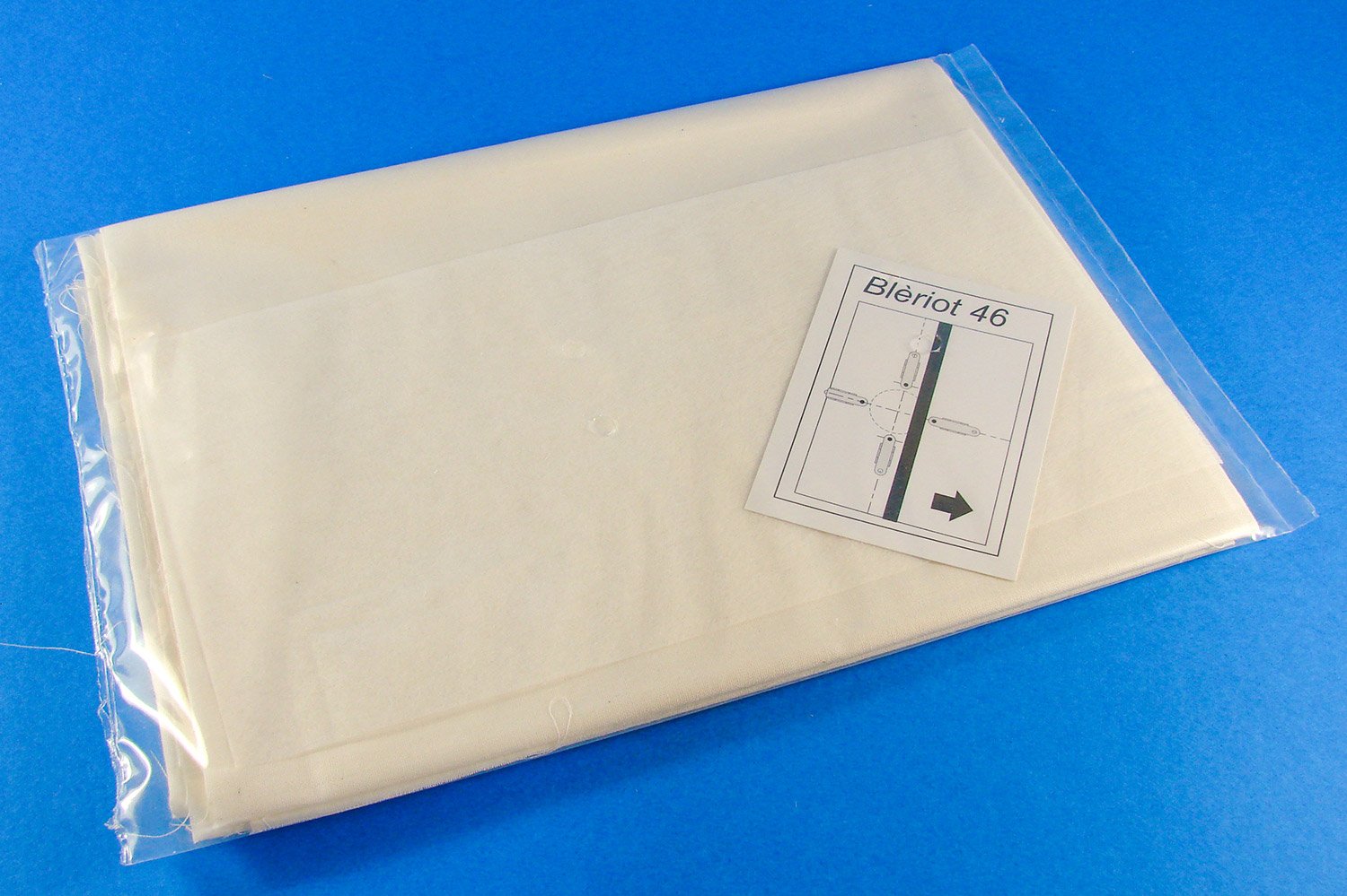
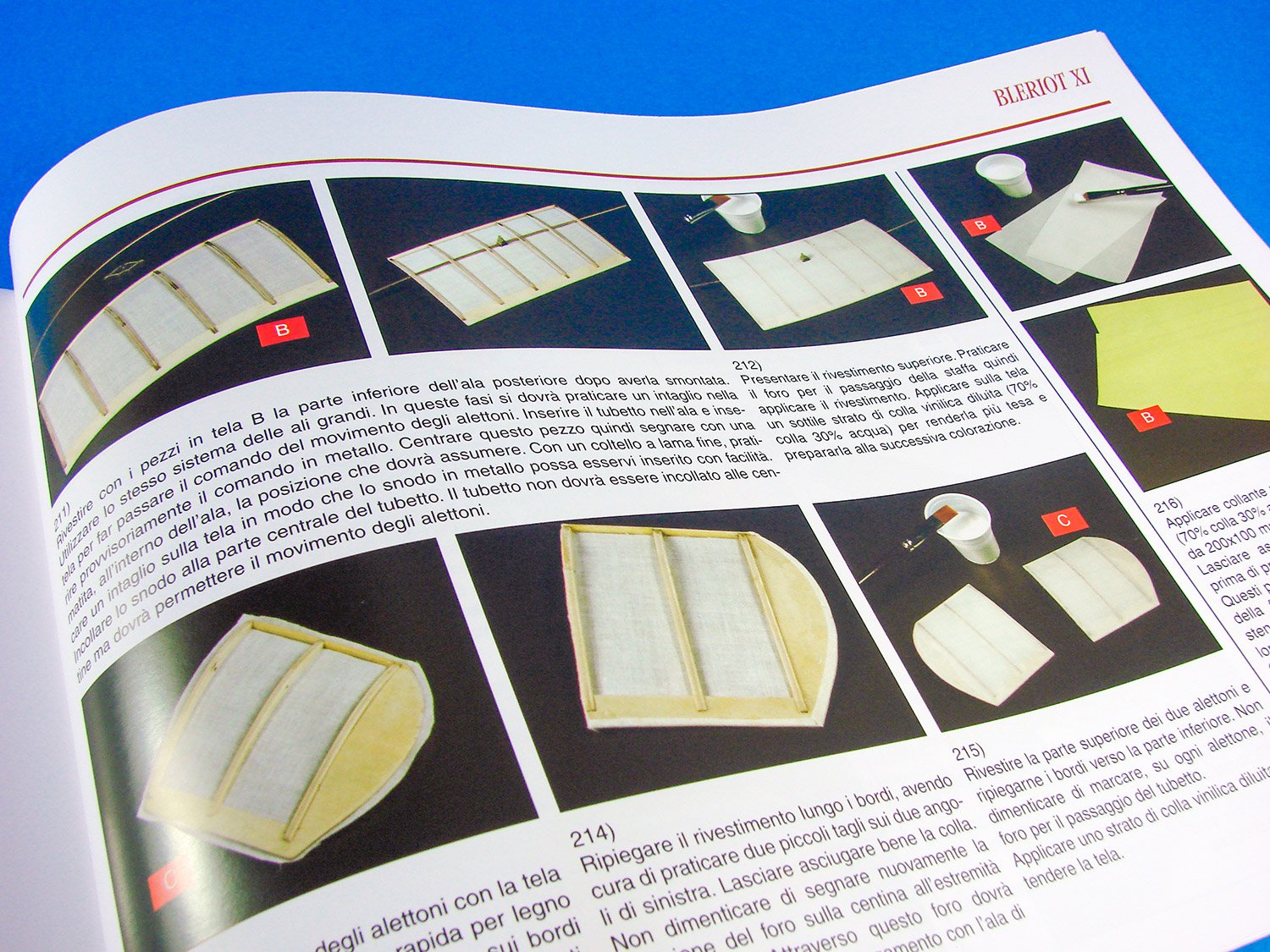
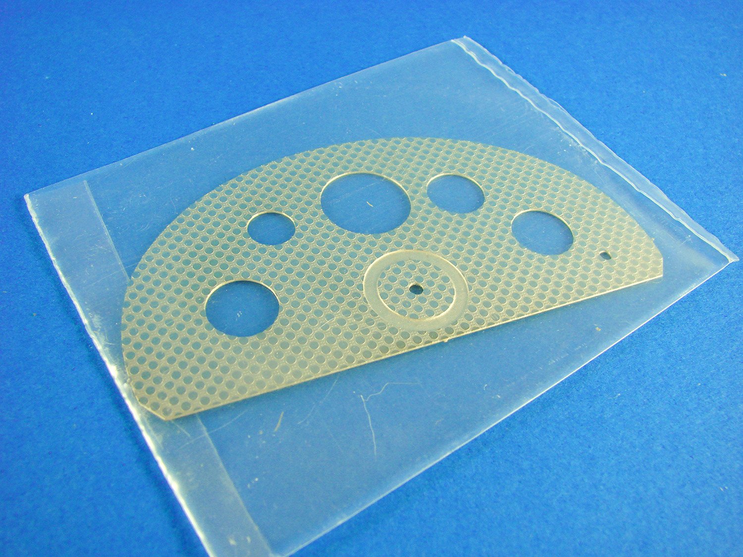
This is the material for covering the wings, tail and part of the fuselage. After being cut to size, this is applied with PVA and CA before being painted all over in dilute PVA. This will give it a smoother and more drum-like surface and of course, pull it taught.
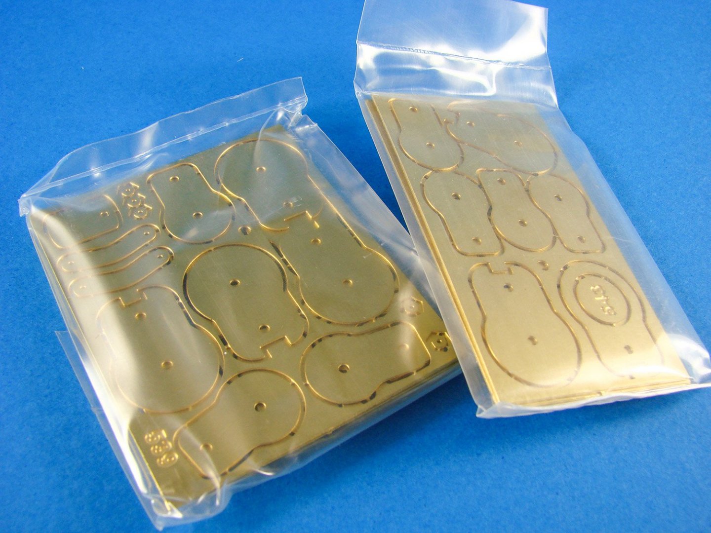
For a model which at first glance, appears to be mostly stick and string, there’s a surprising amount of photo-etch.

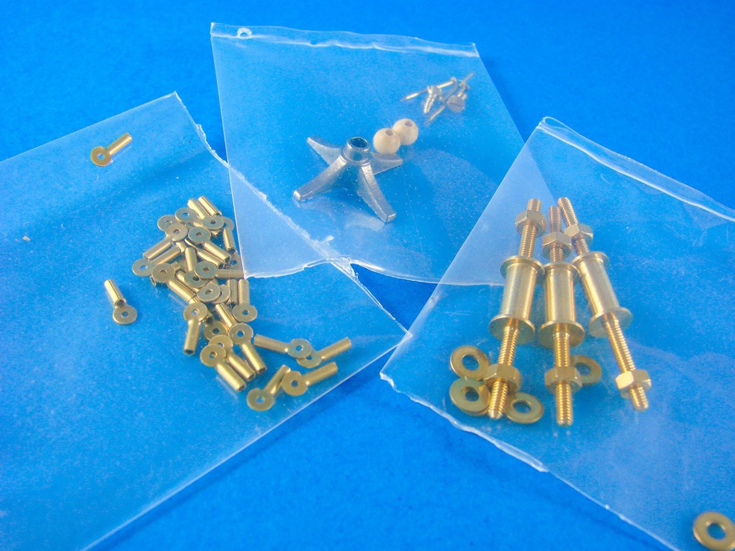
The second fittings tray. Let’s take a look…
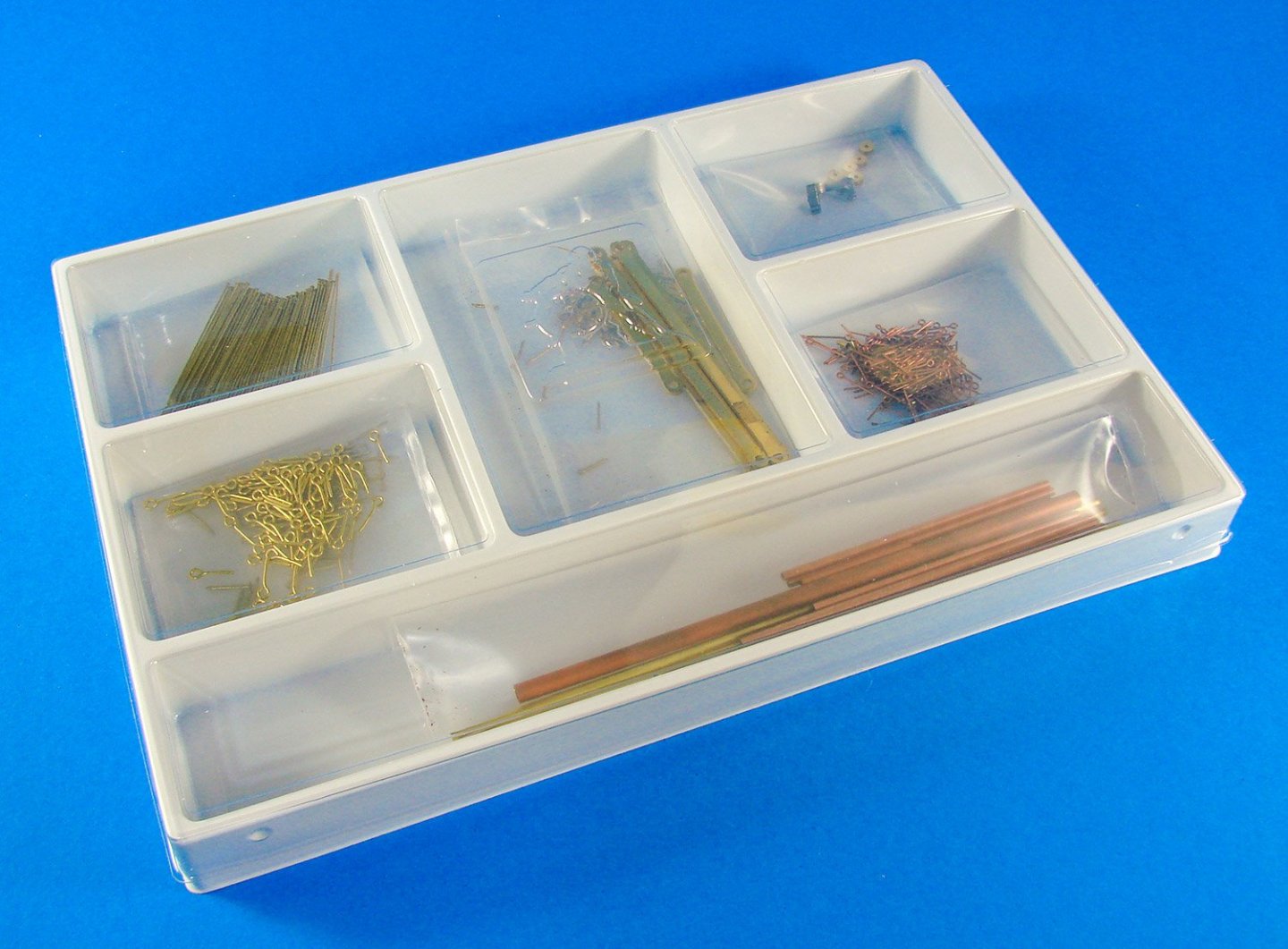
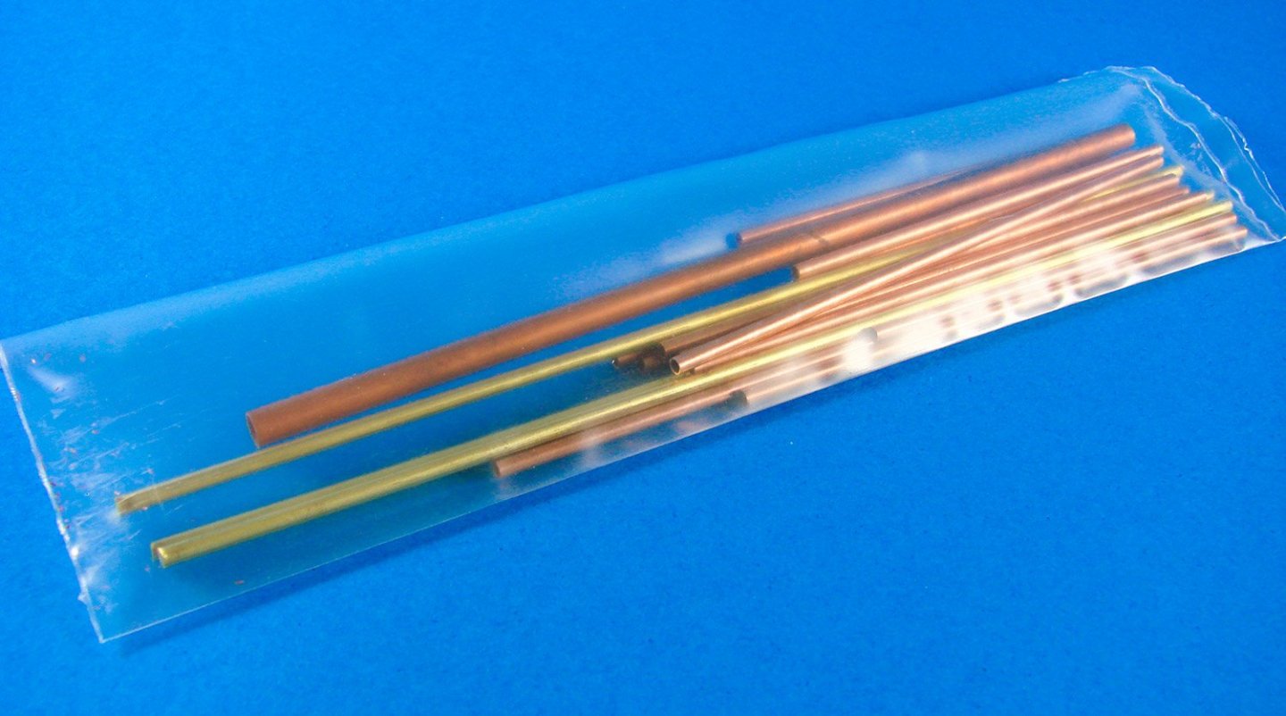
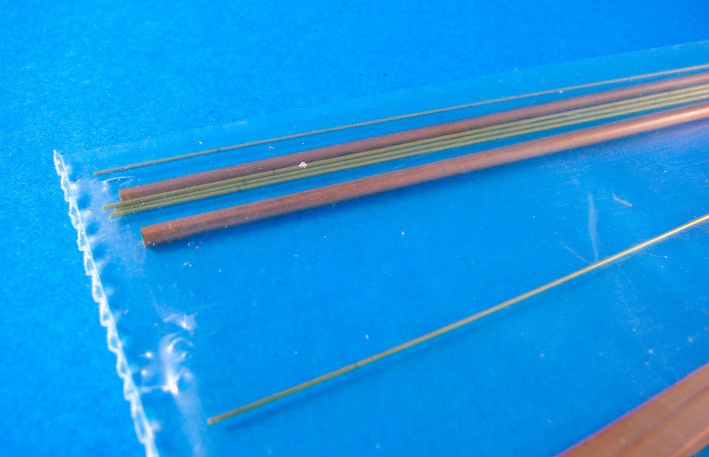
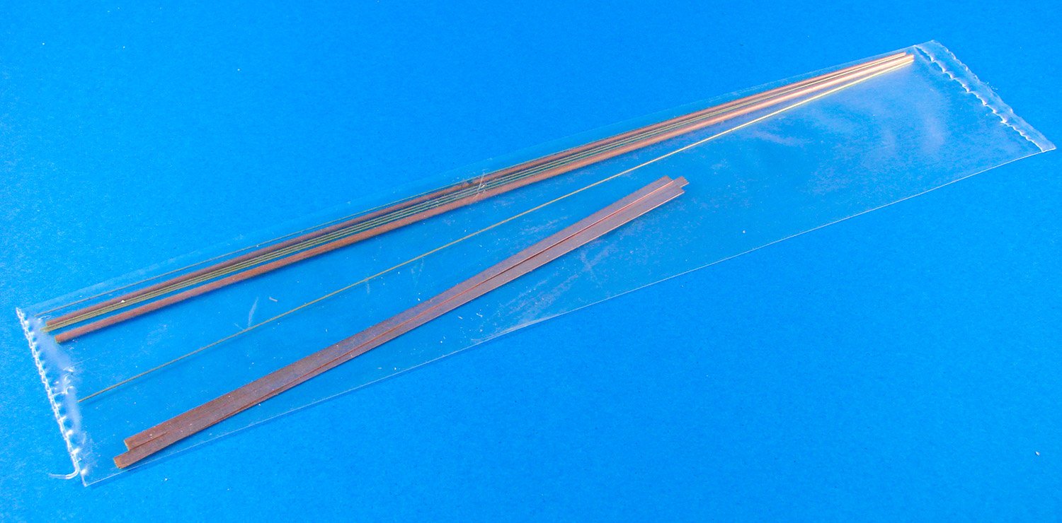
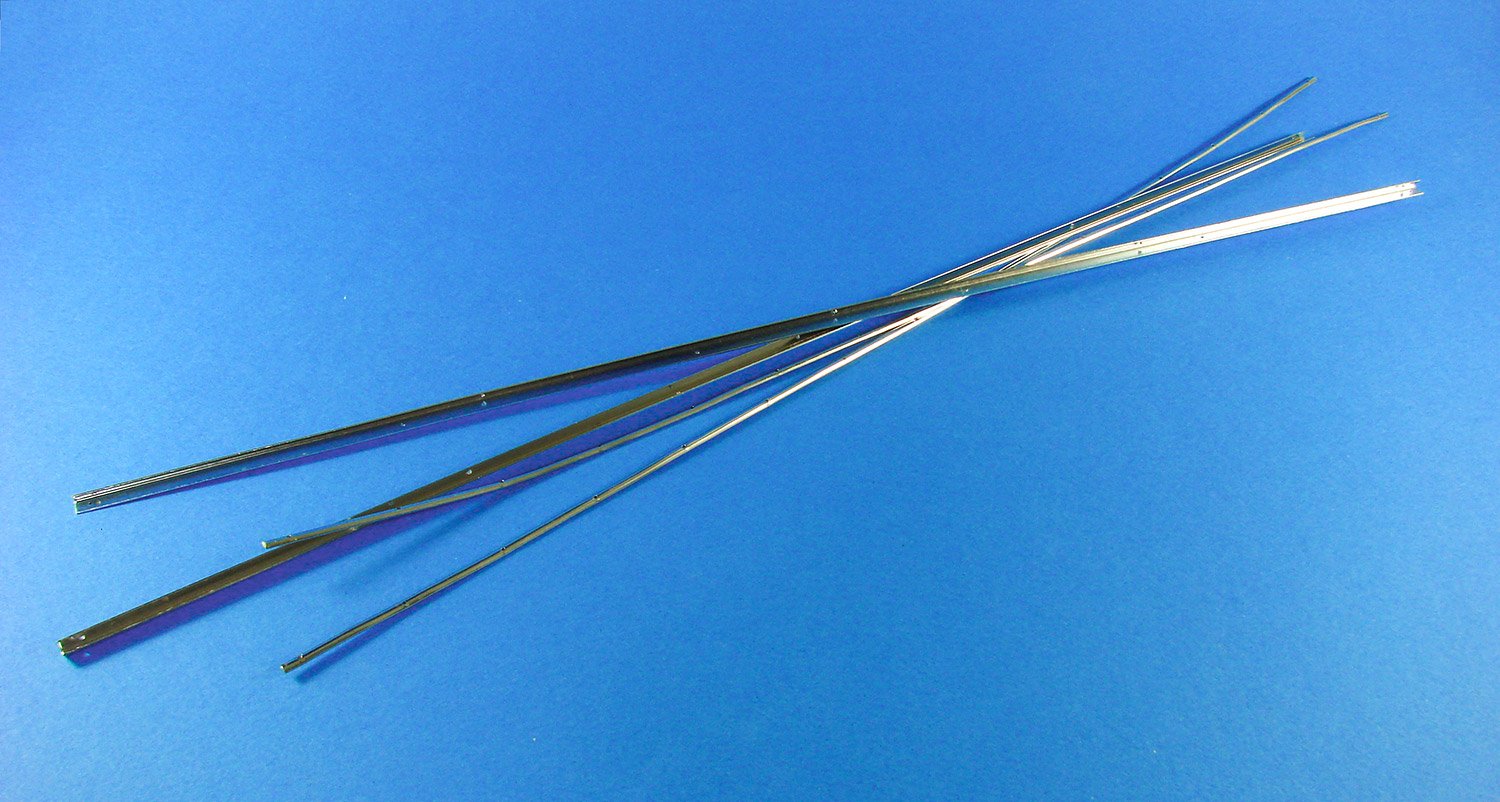
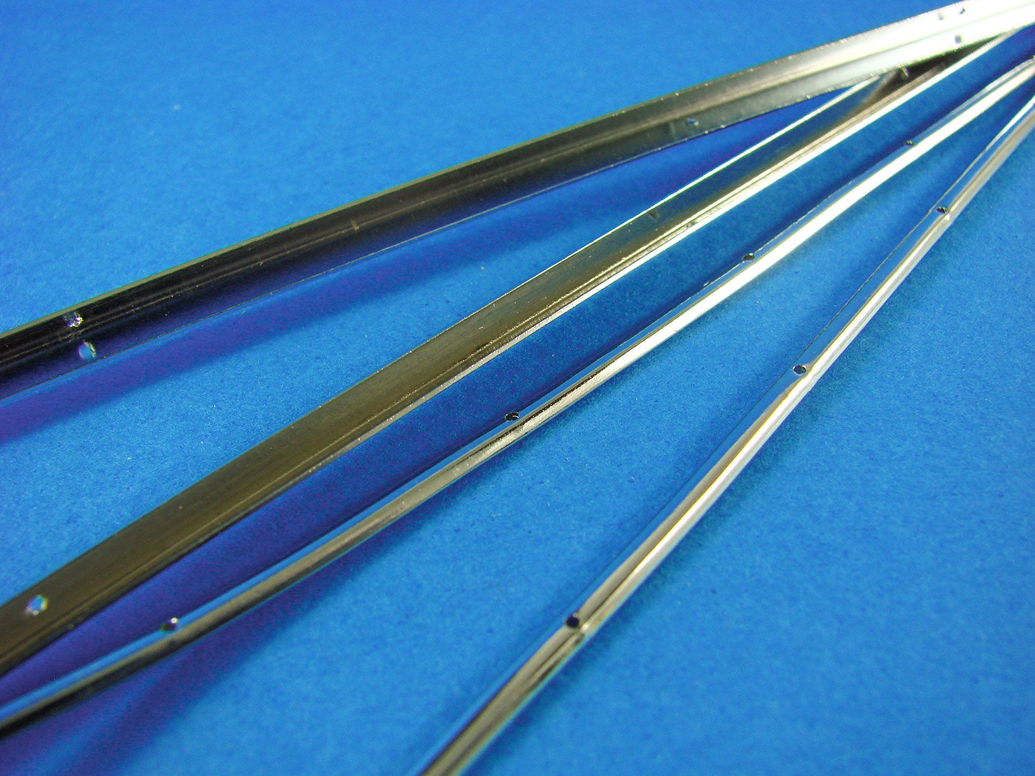
As the aircraft has numerous pivoting surfaces and pipework, we are supplied with a range of both brass and copper tubes of various lengths and gauges.
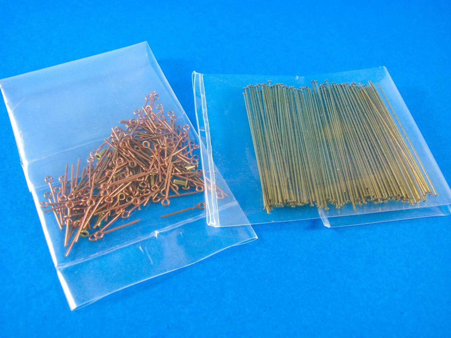
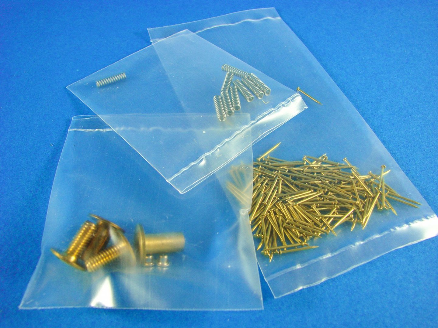
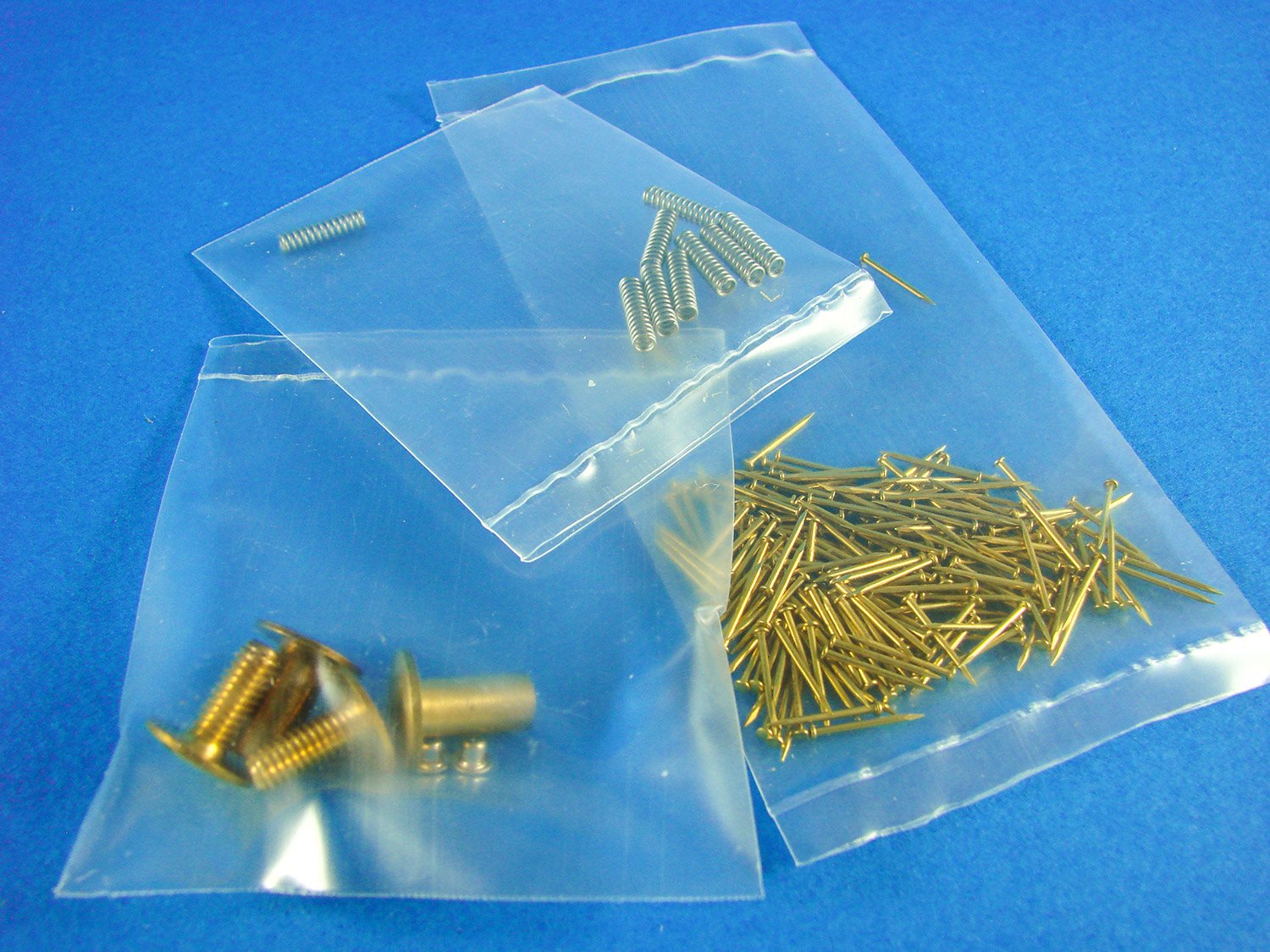
You will of course need some nails too, and some eyelets for things such as rigging.

As well as brass eyelets, a bag of copper eyelets are also supplied. The bag of copper rods you see here are actually the wheel spokes, and they have a flat end on them to secure them in the jig whilst you assemble the wheels.
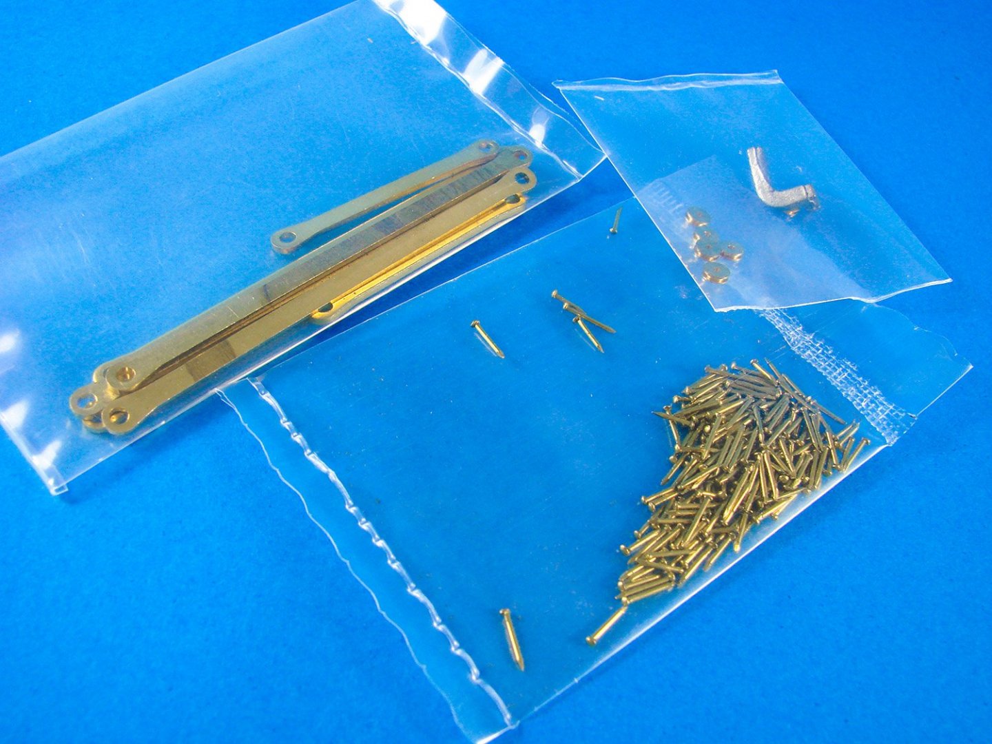
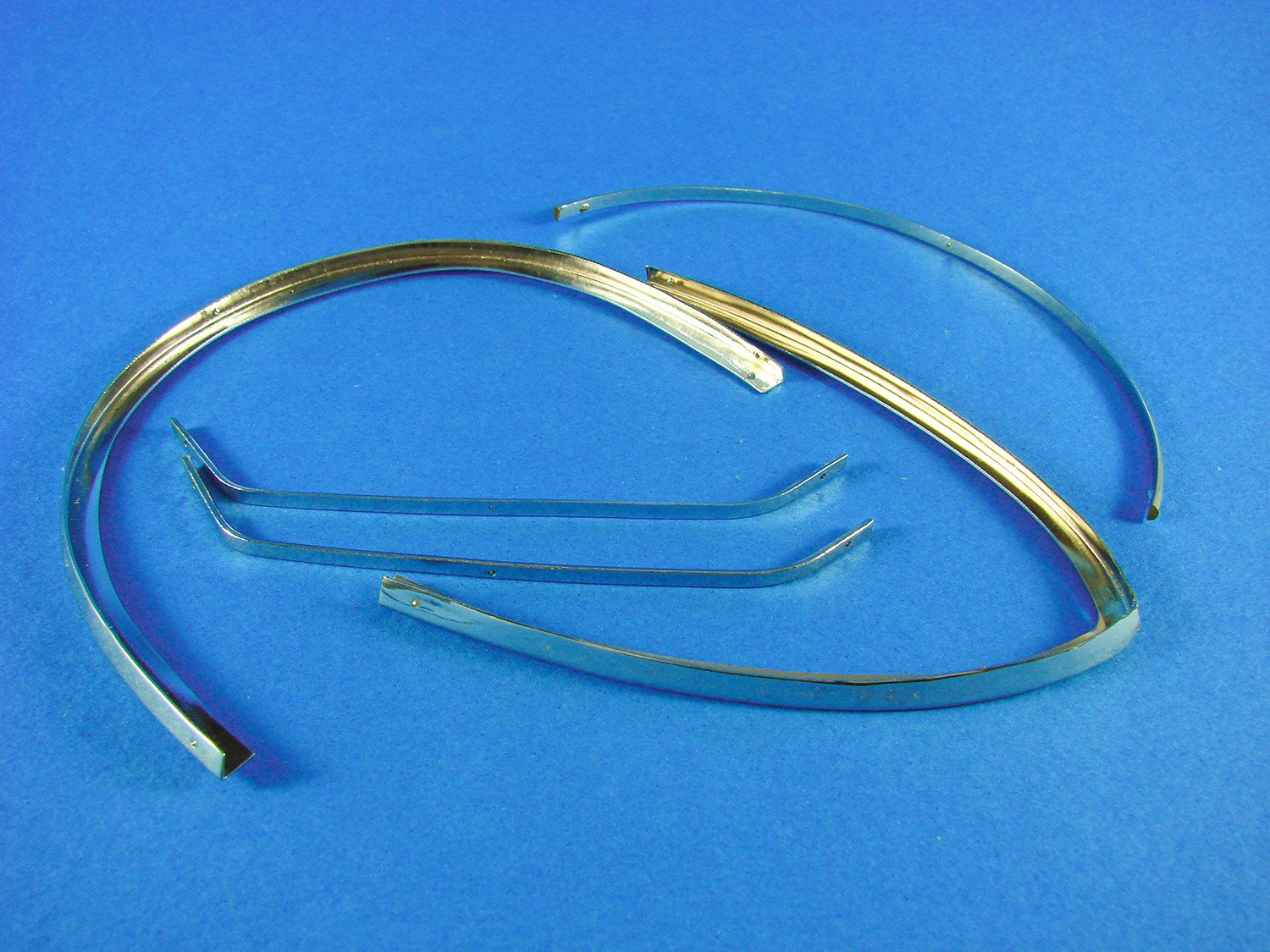
Yet more brass nails and also brass strip parts which appear to be undercarriage related.
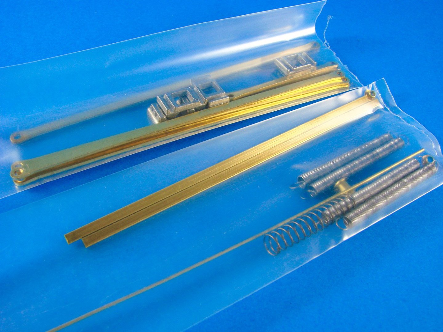
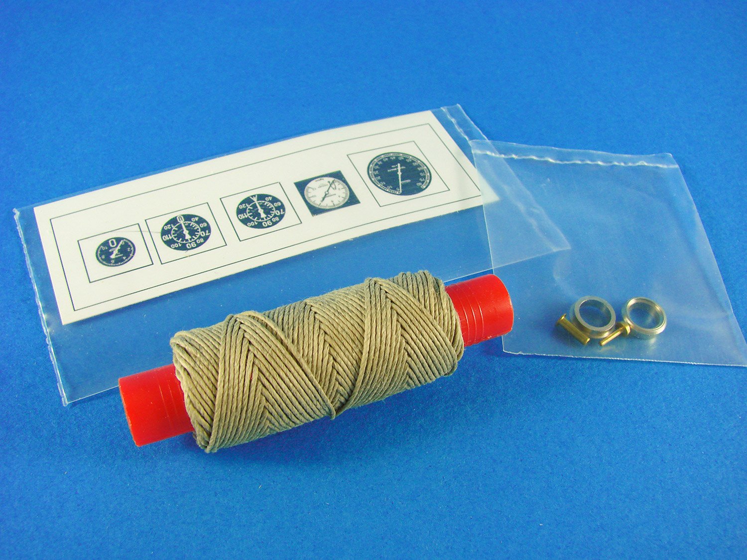
Our last components tray.
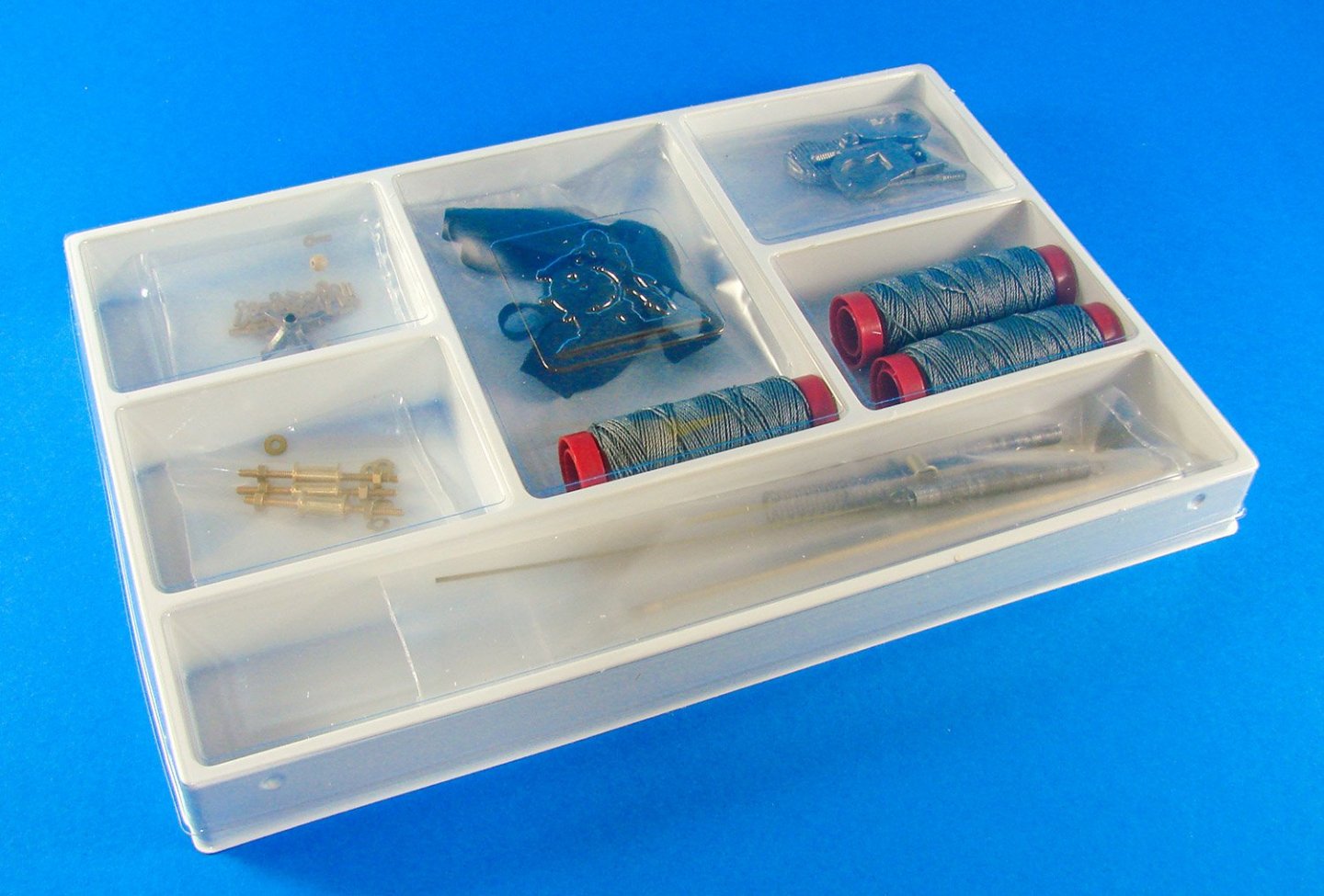
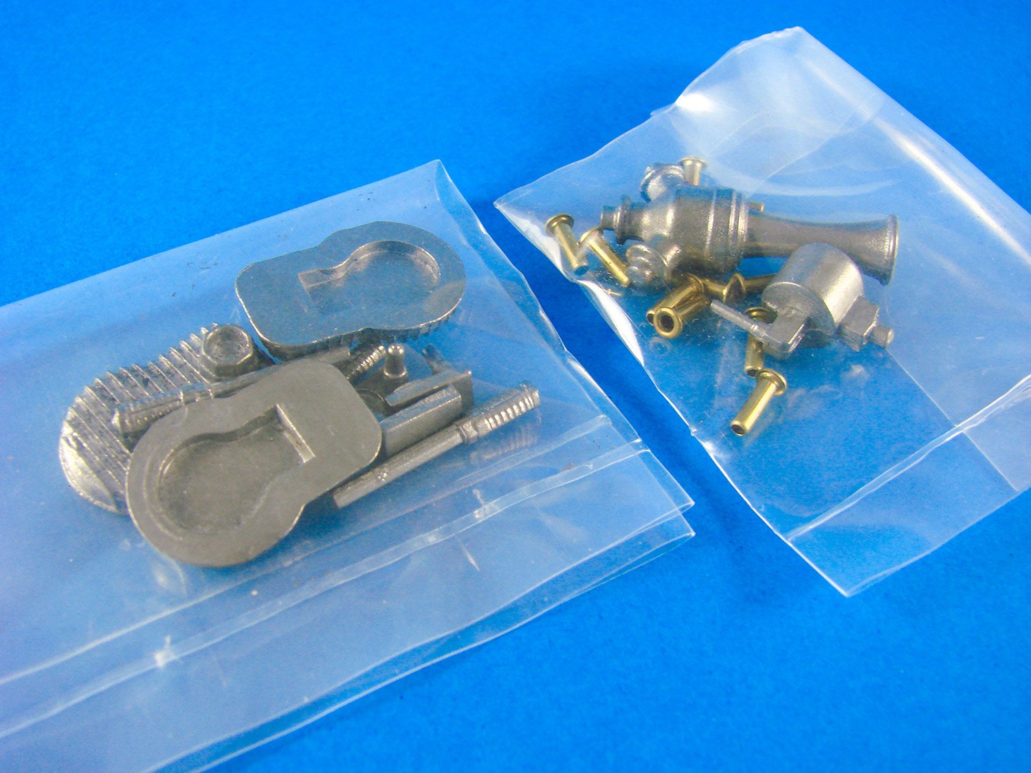
In here, we have various brass eyelets, engine components such as cylinder heads, large turnbuckles, undercarriage suspension springs, brass rod, riggings cord, plumbing parts etc. Quite a few parts here are cast in zinc alloy as they are stronger and hold detail far better than white metal or Britannia metal fittings.


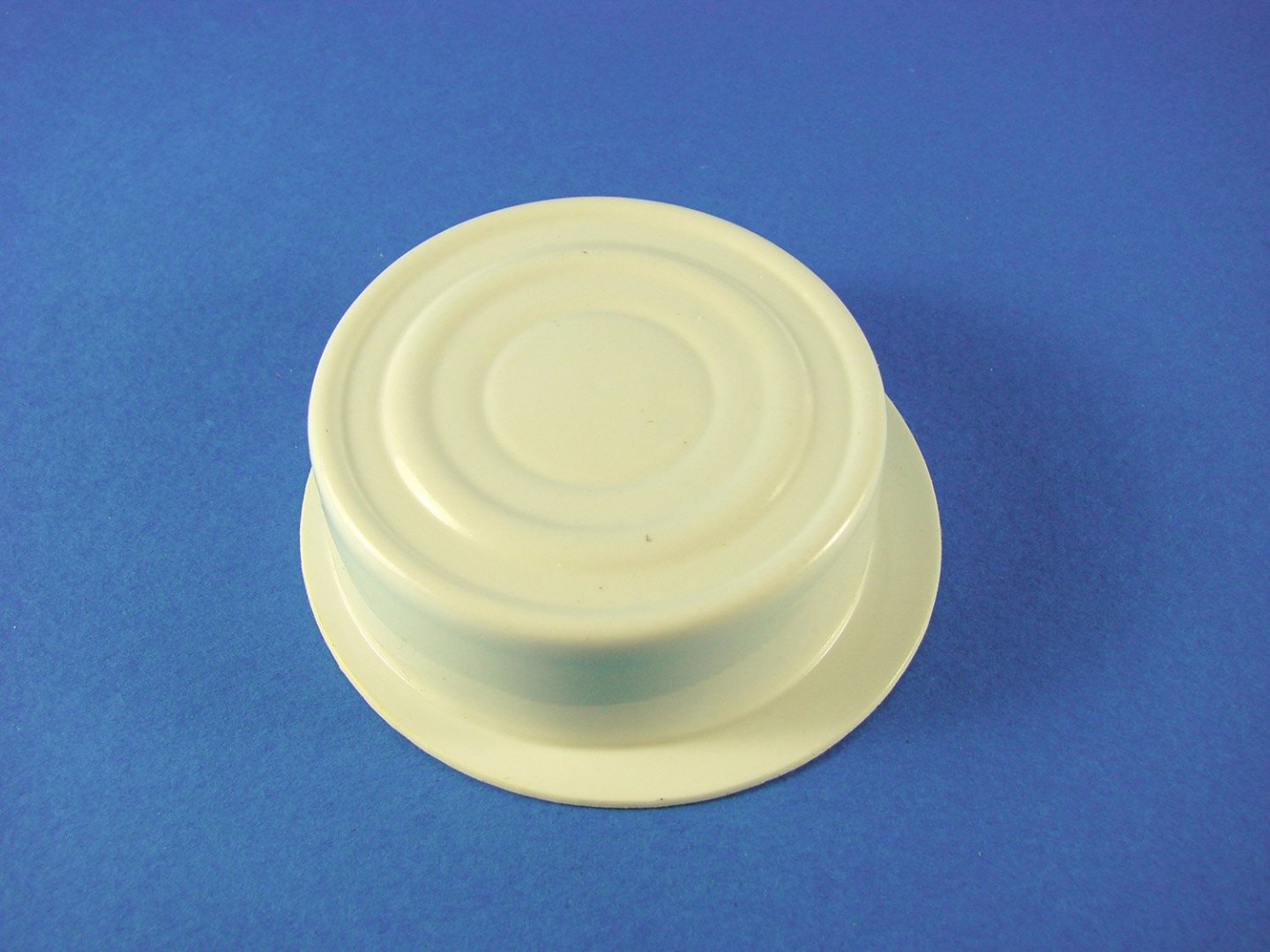
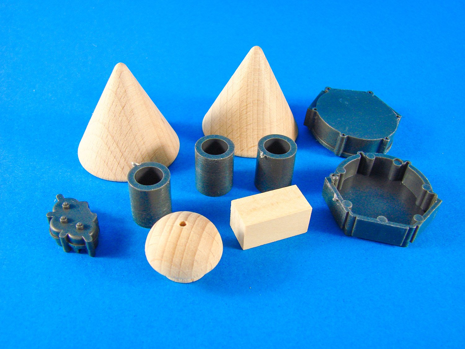
This little pack of curios contains parts in both timber of plastic. The cones form the ends of the large fuel tank for which you’ll need to construct a planked drum. Parts here exist for the control stick base, cylinder bases and the engine crankcase etc. Some minor clean-up of the plastic parts will be needed.

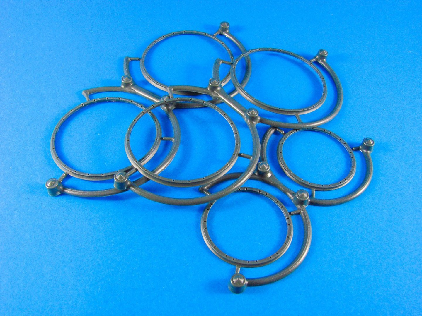
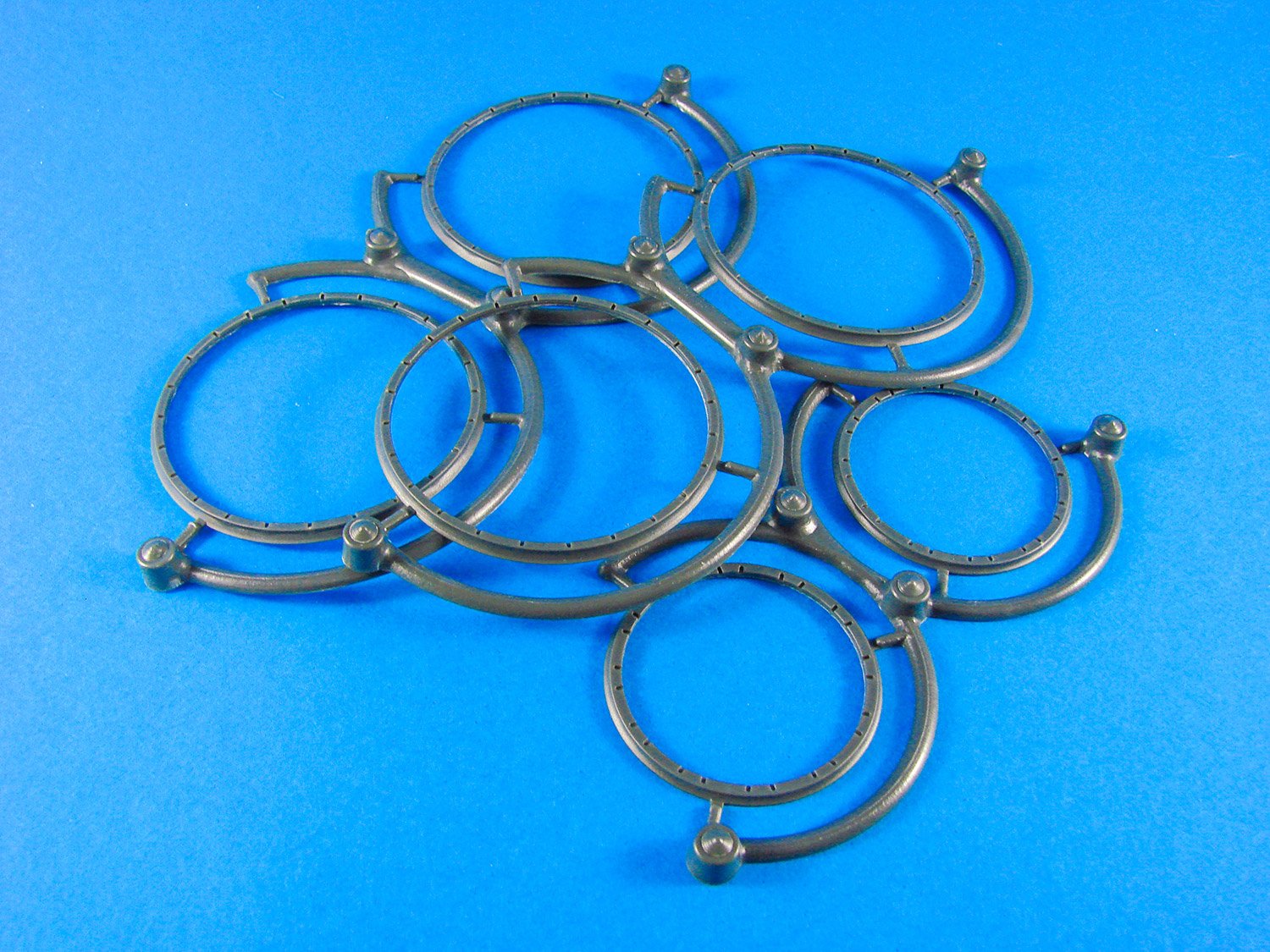
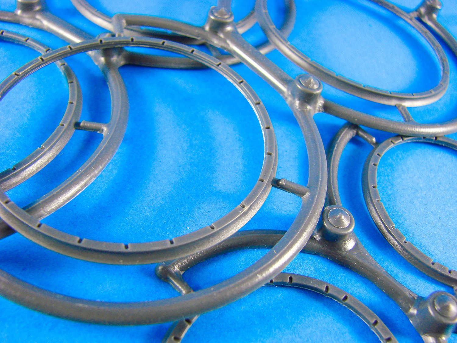
Injection moulded rims are supplied for the wheels, with two per wheel. These will be assembled on the jig, and along with the brass hubs, they will be spoked just like the real thing. Minor clean-up will be needed to remove the sprue attachment gates.
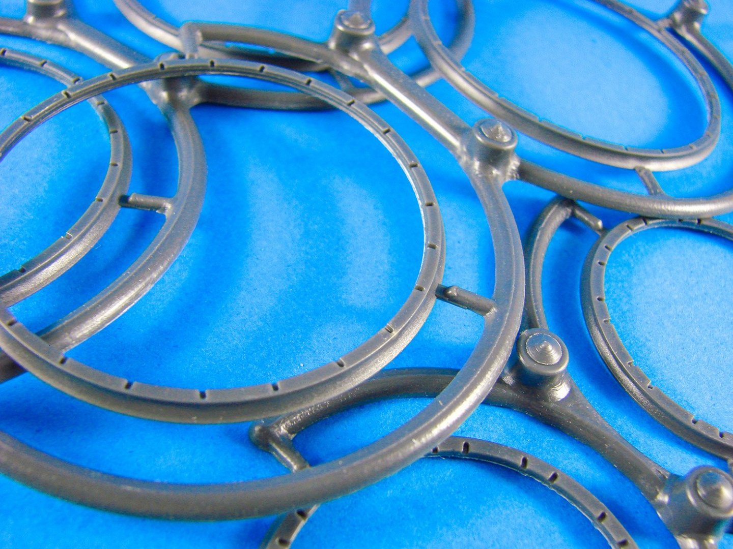
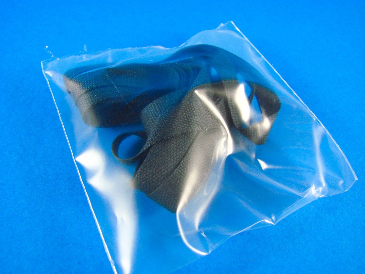
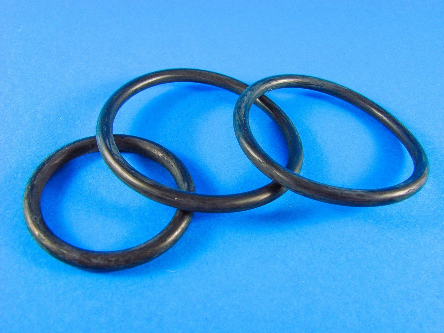
Large rubber rings are supplied for the tyres, and these will sit neatly into the recess between the two rings that make up each wheel.
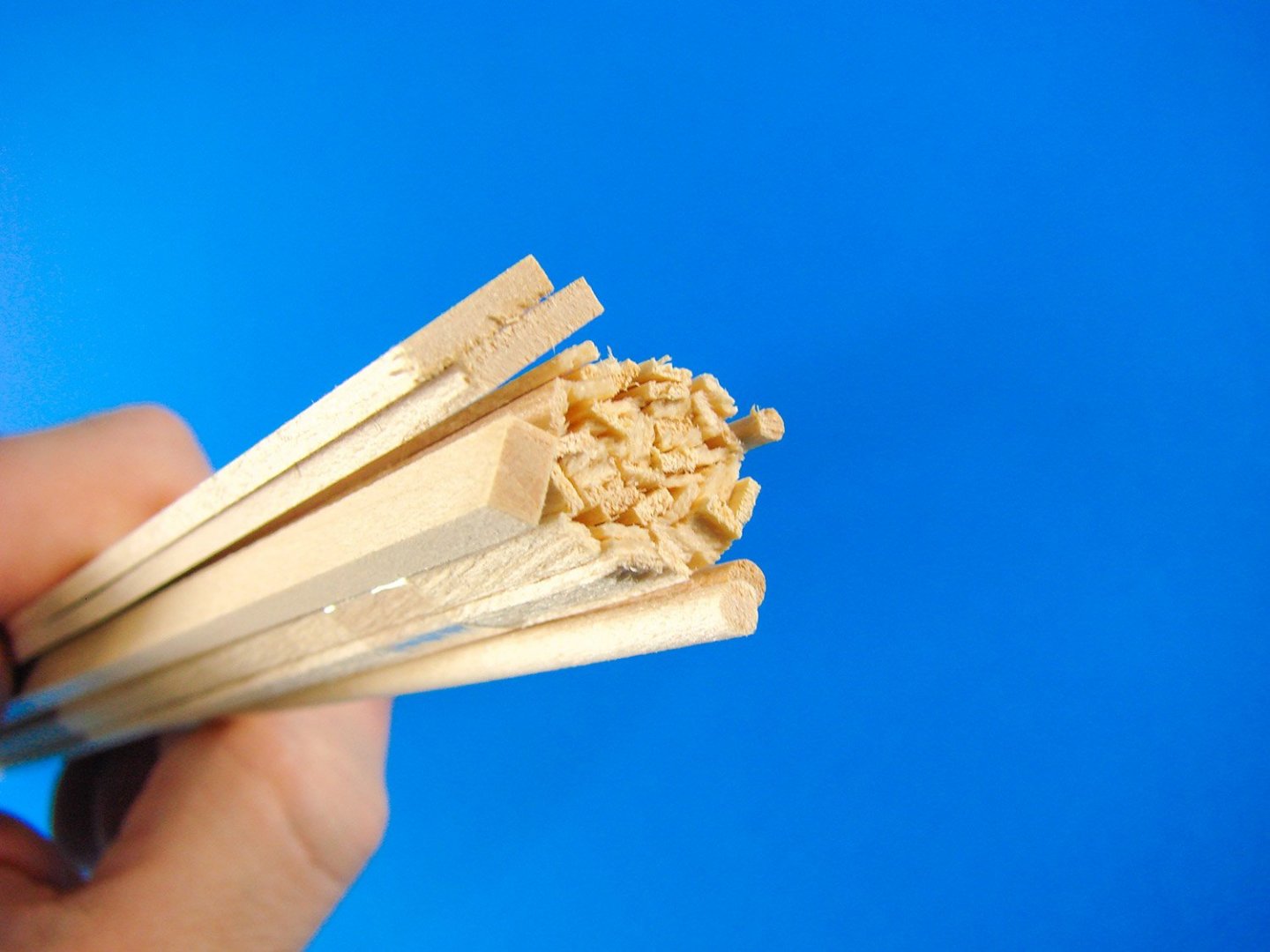
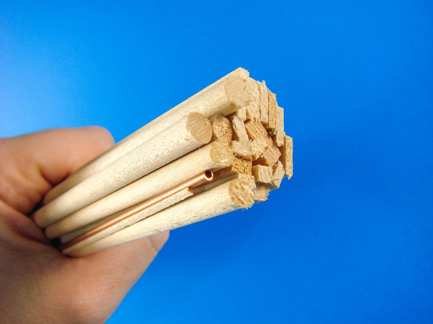
Yet more brass and copper tubes/rod.

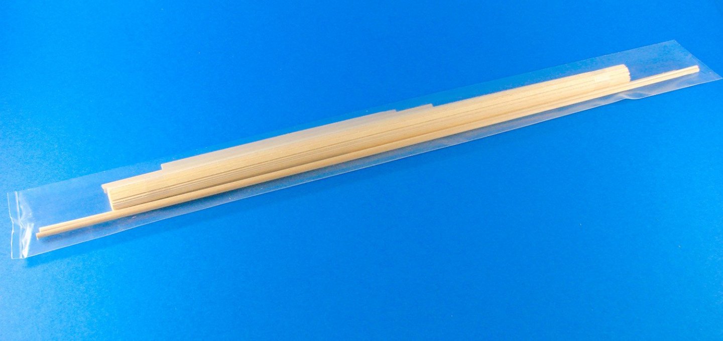
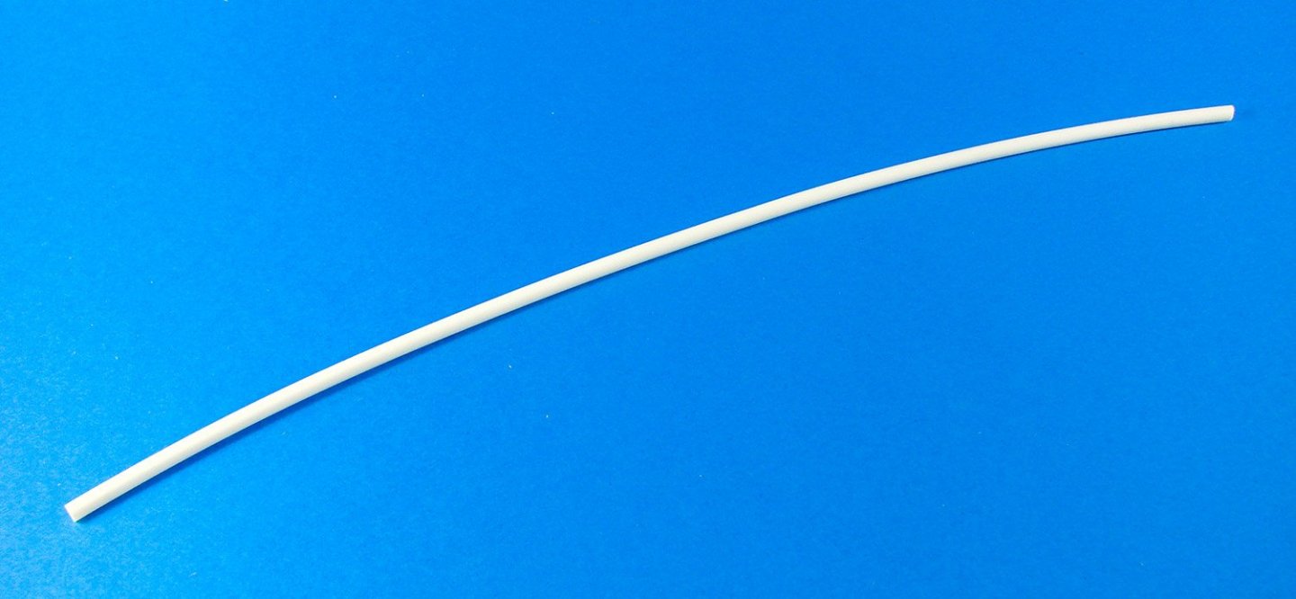
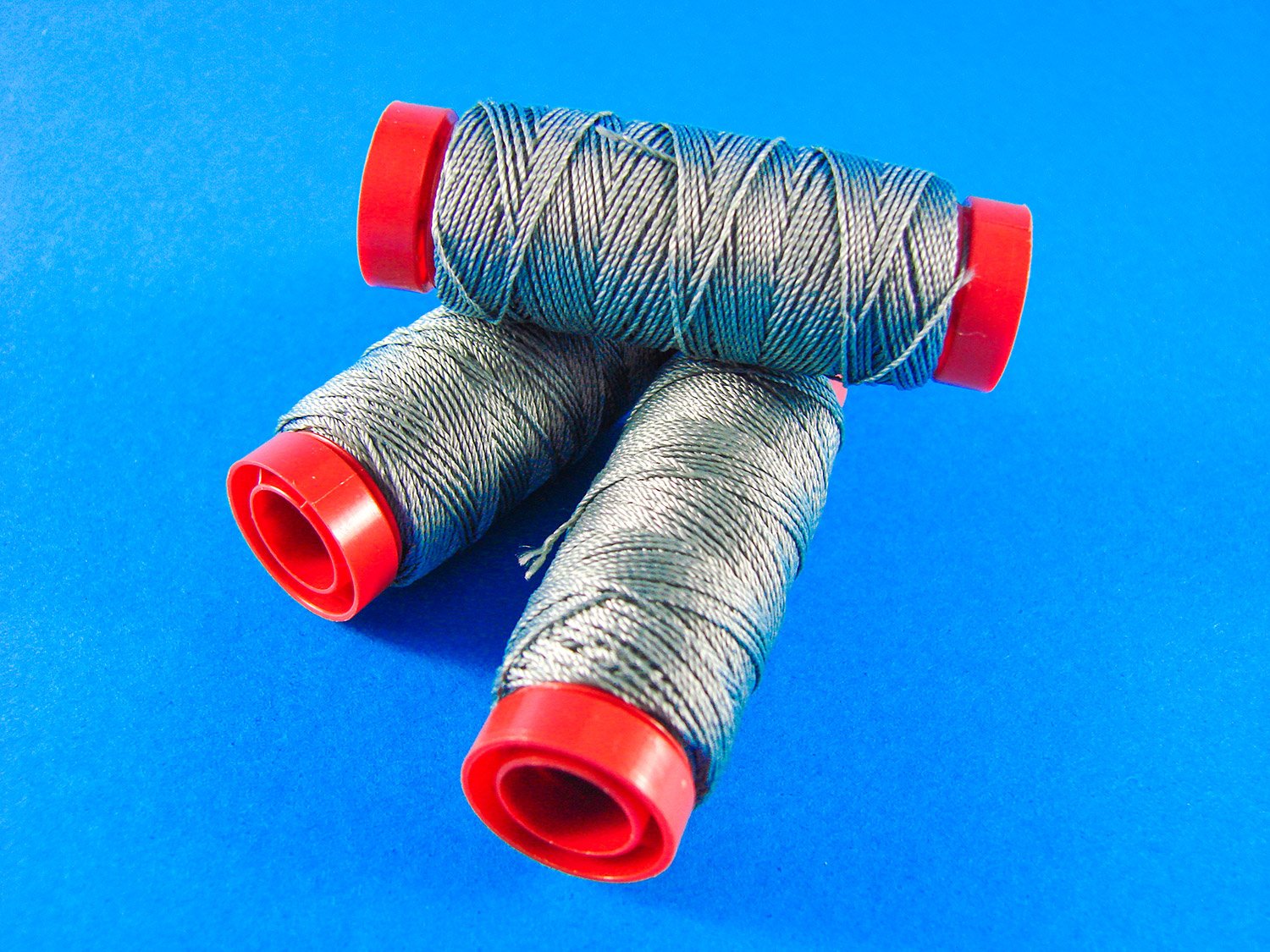
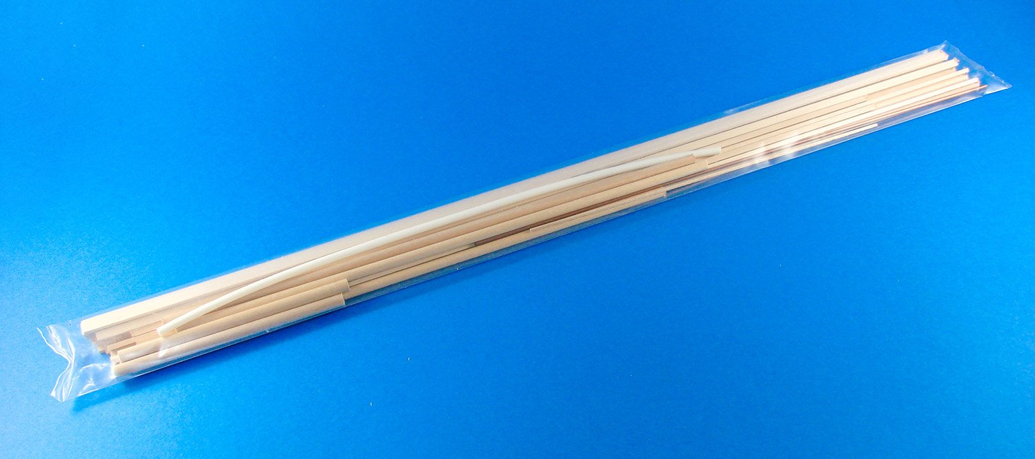
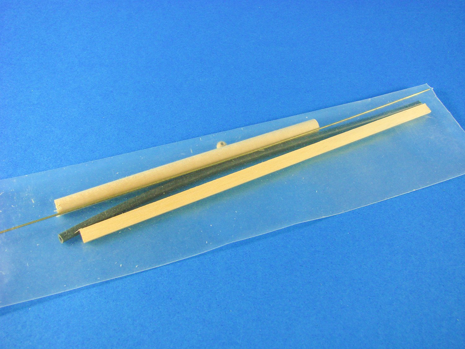
Of course, we can’t have a wooden model without timber strip. This will be used for some frames, wing/tail spars, leading edges etc. Timber quality is Amati standard, as always. Some flexible pipe is also supplied for plumbing the engine, fuel tank etc.

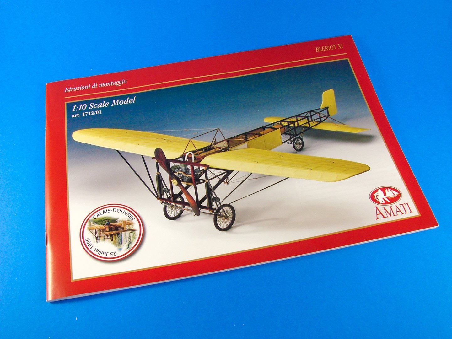
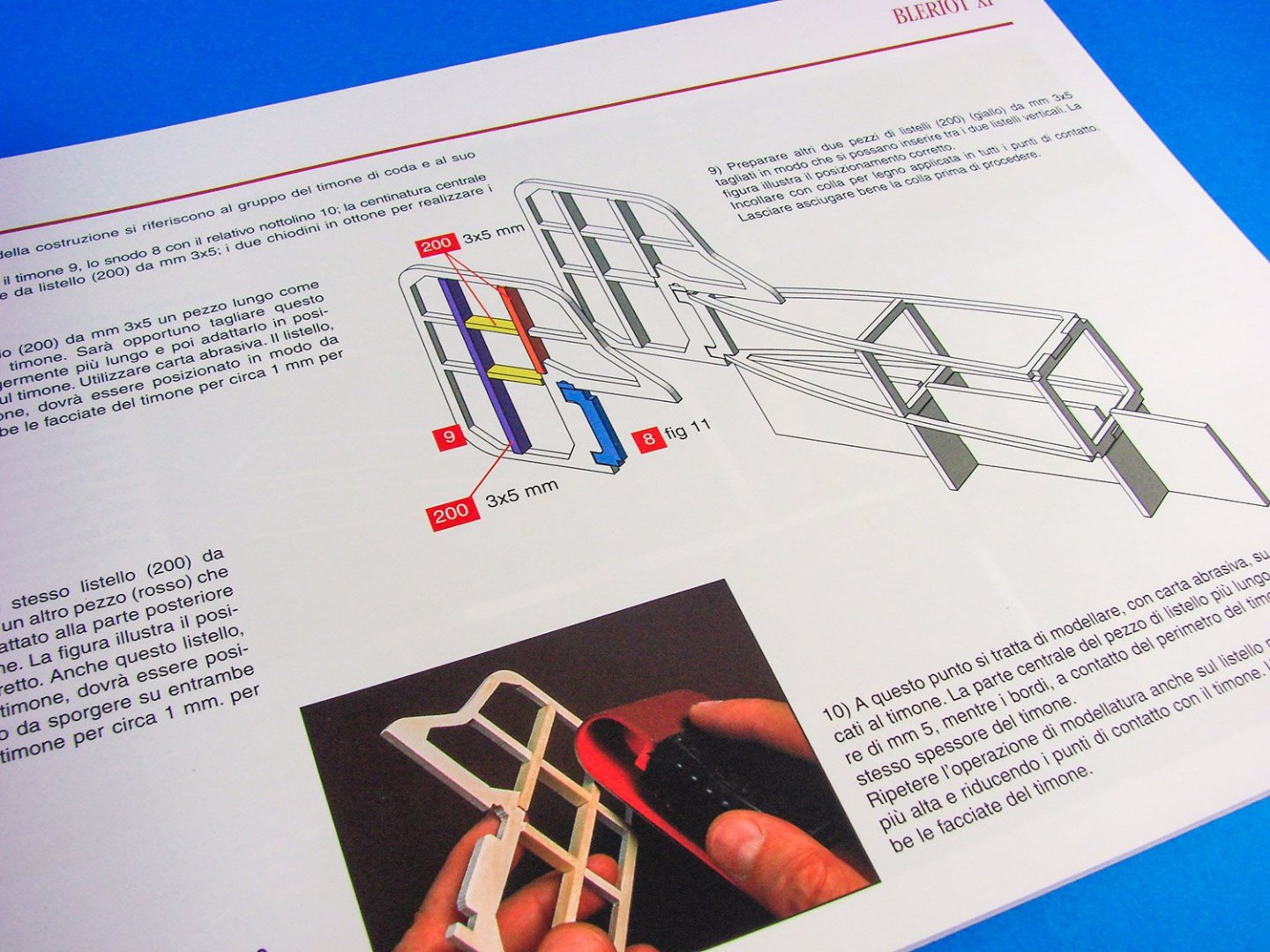
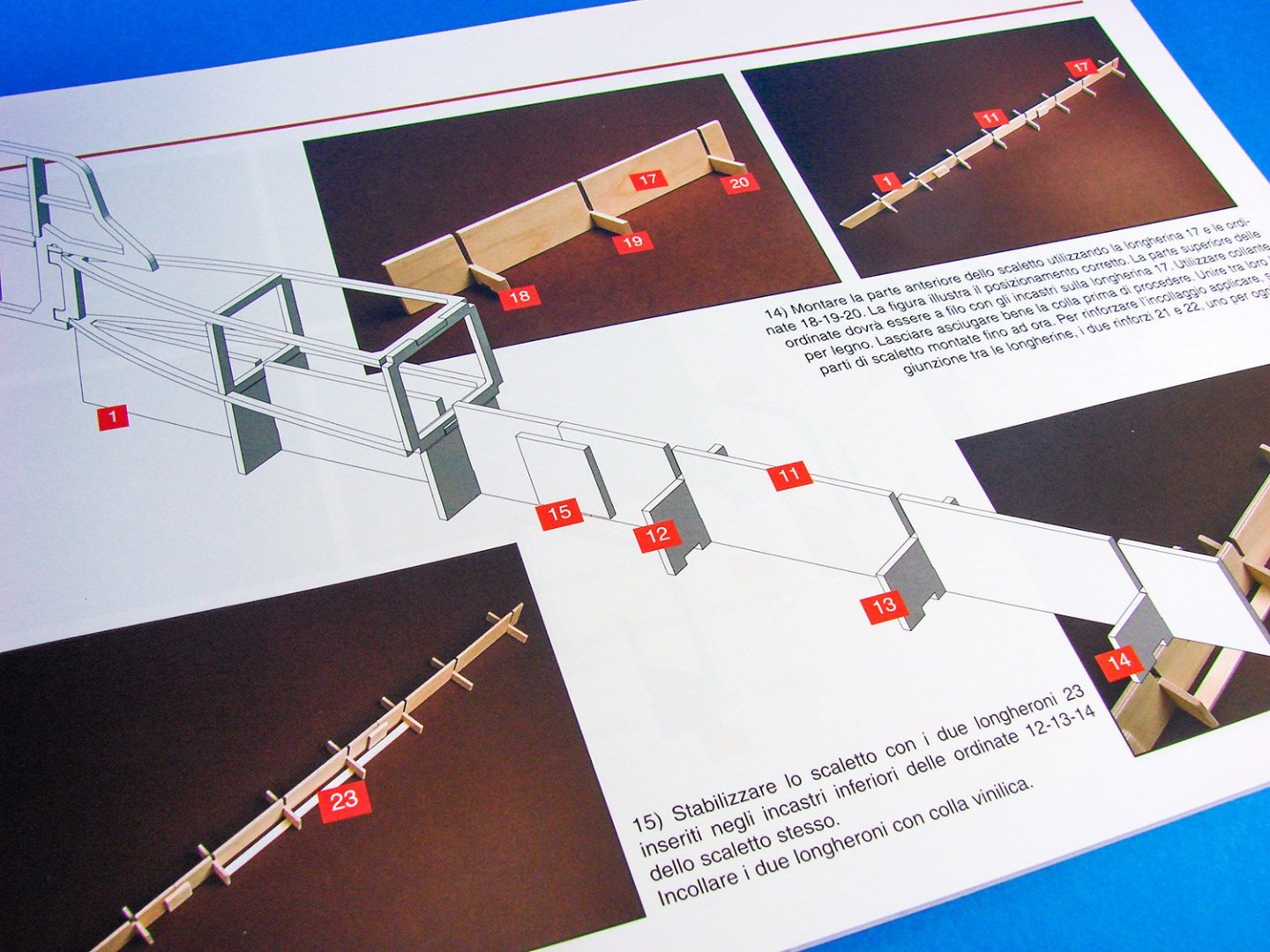
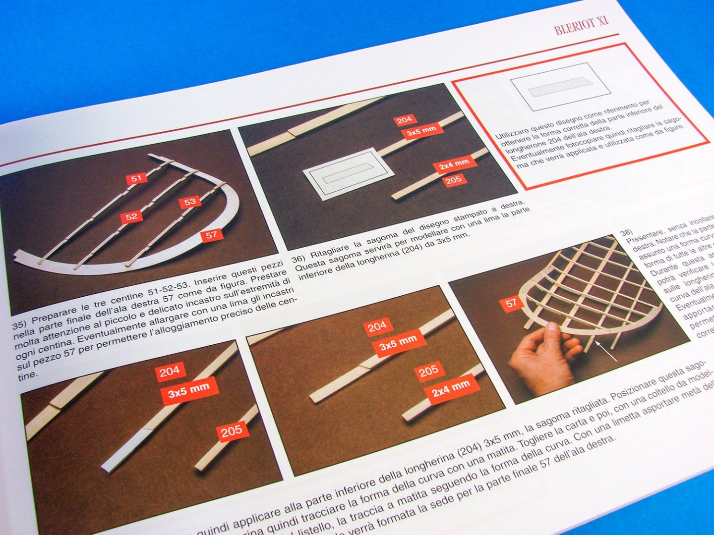
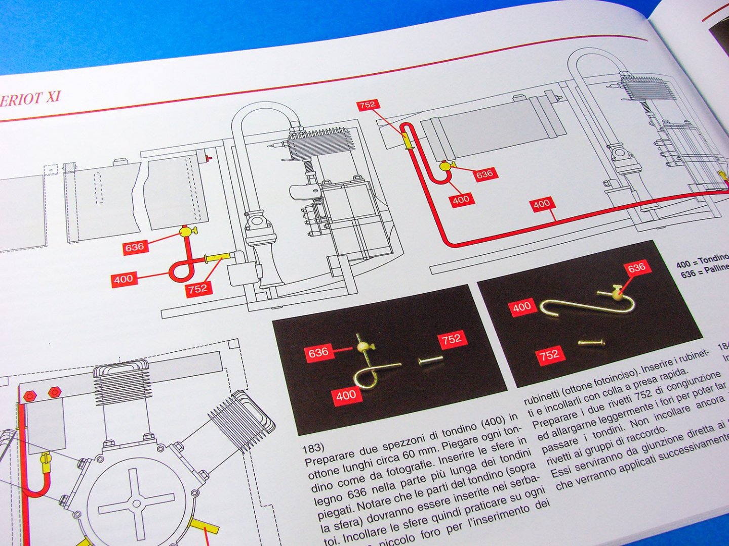
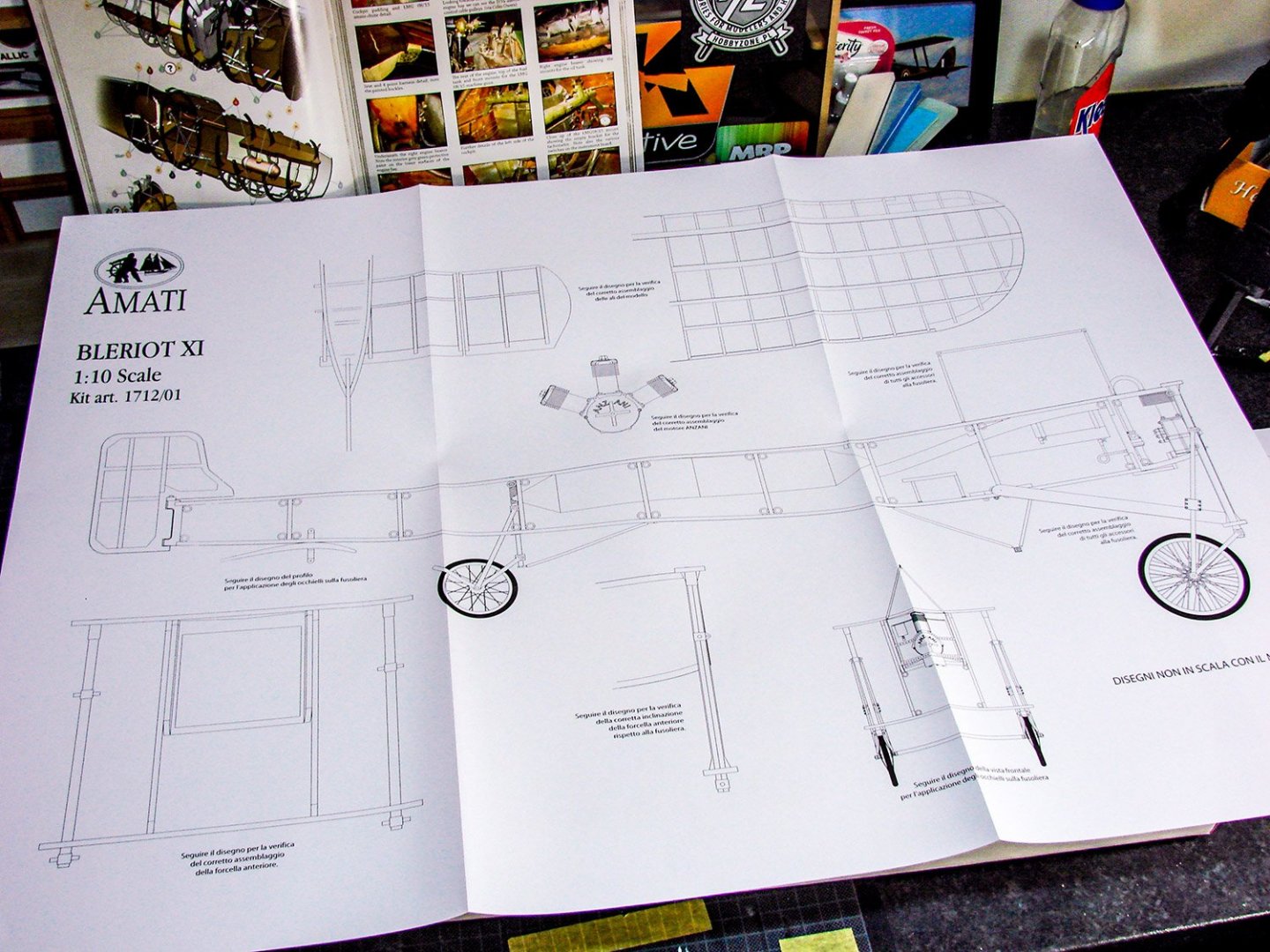
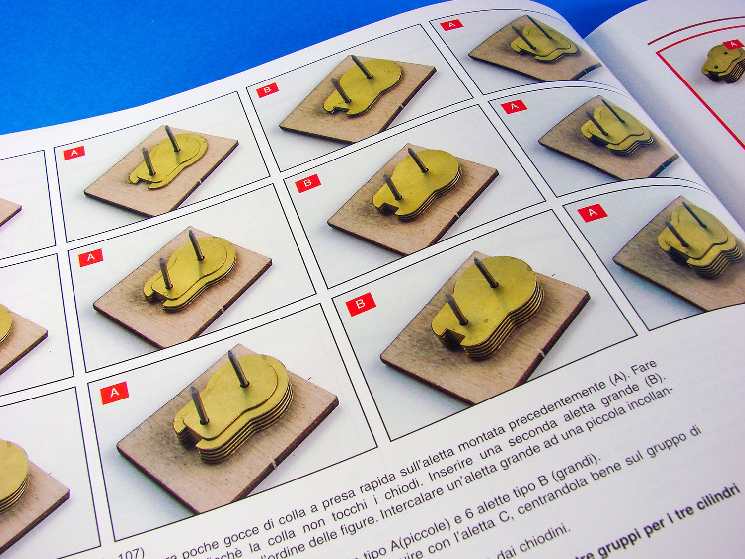
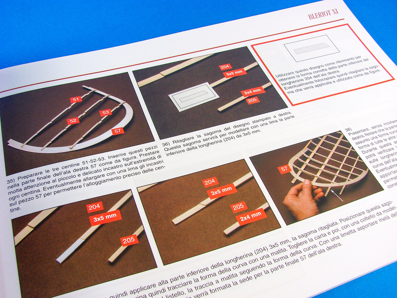
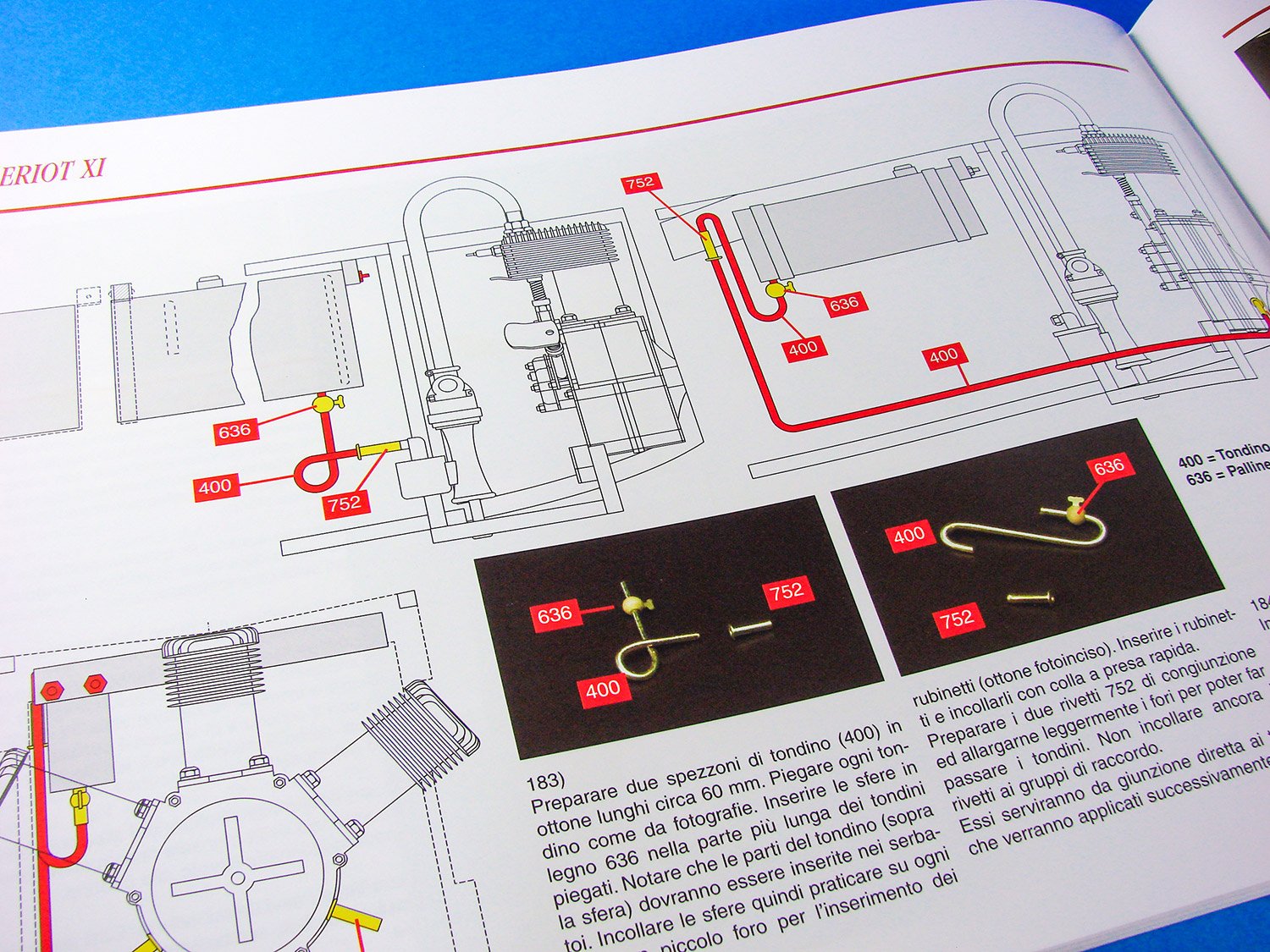
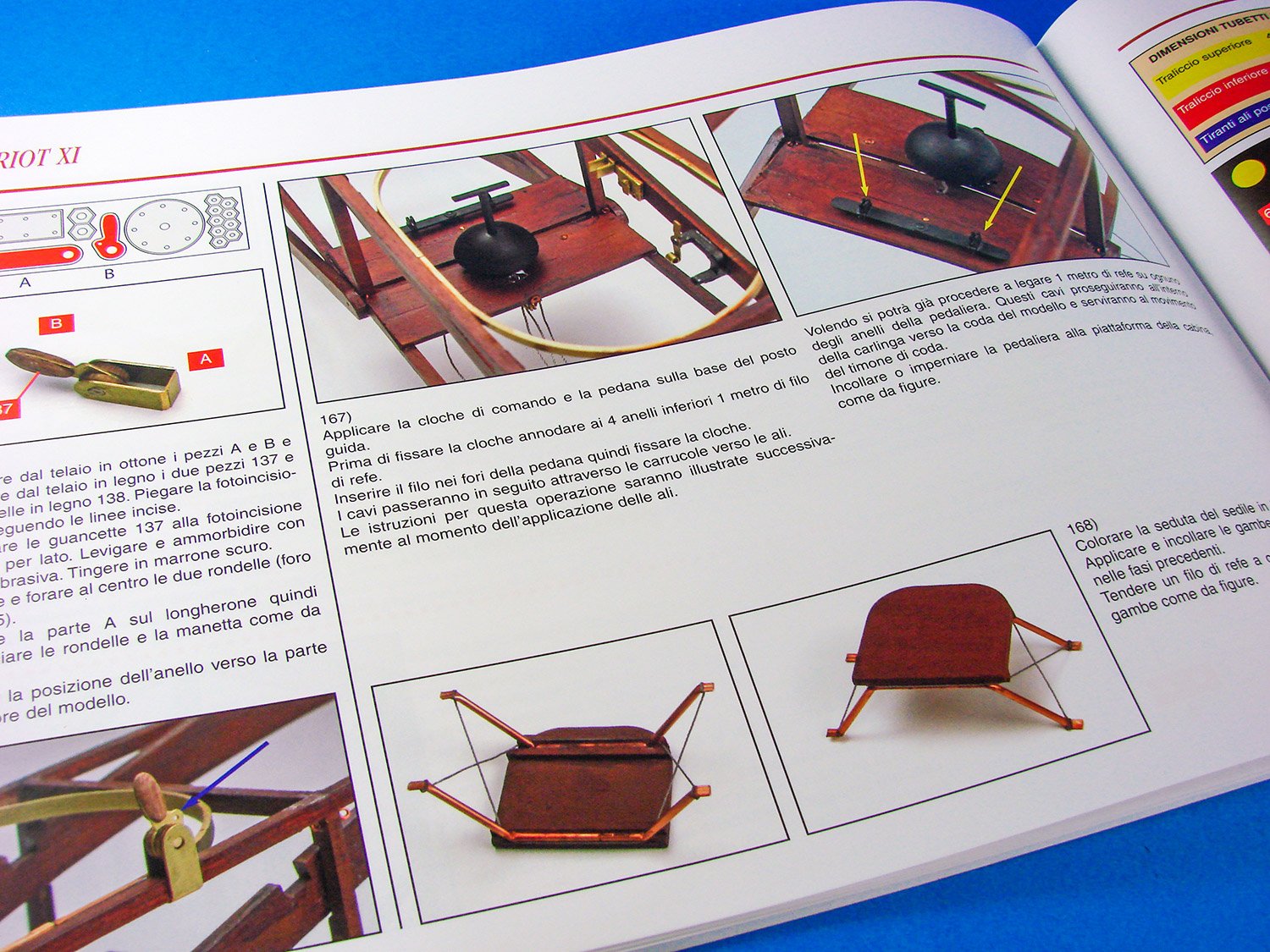
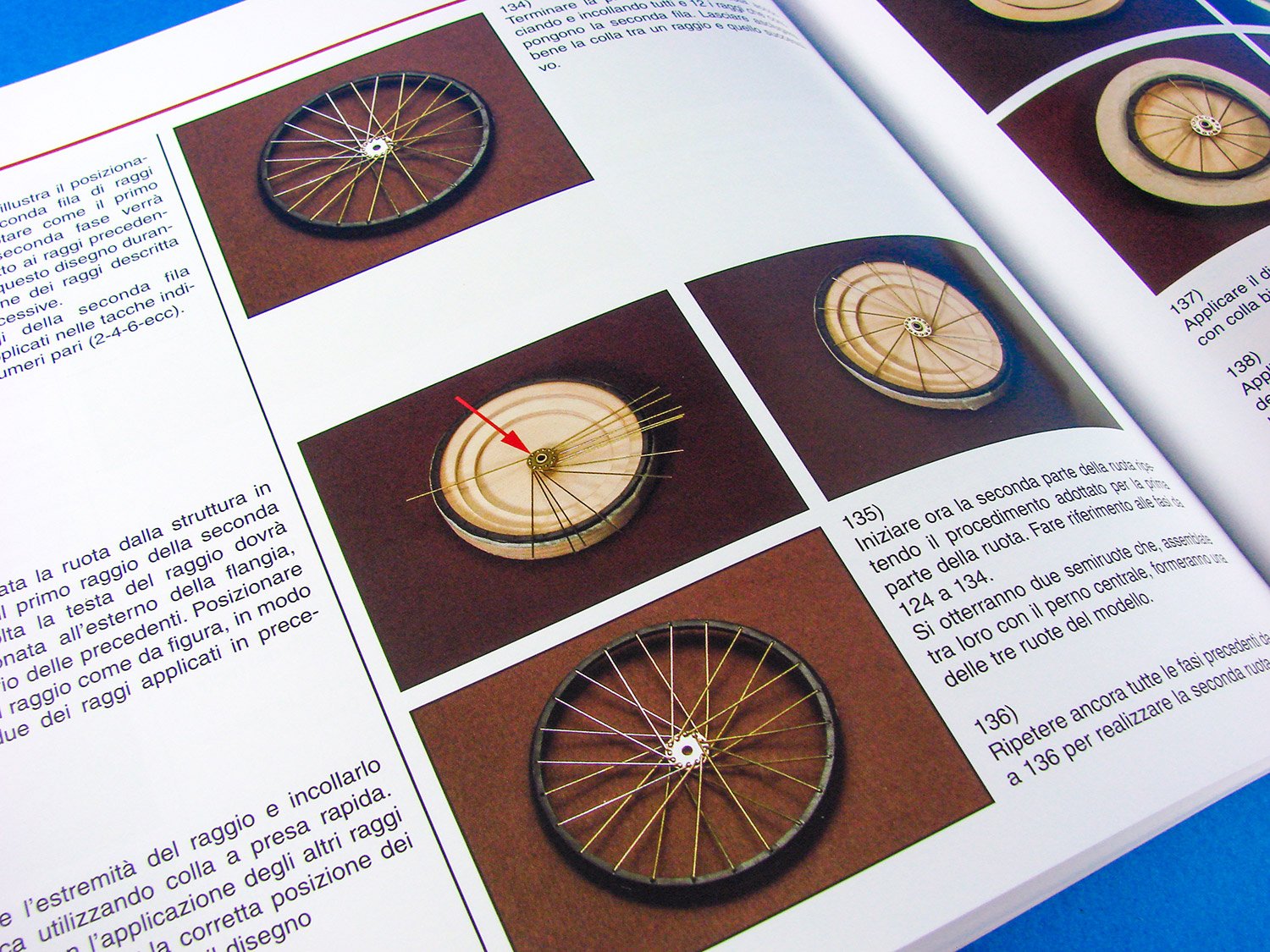
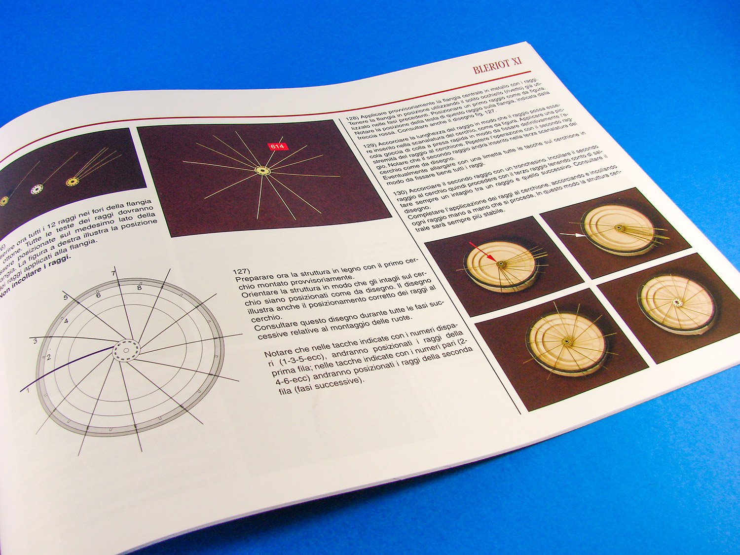
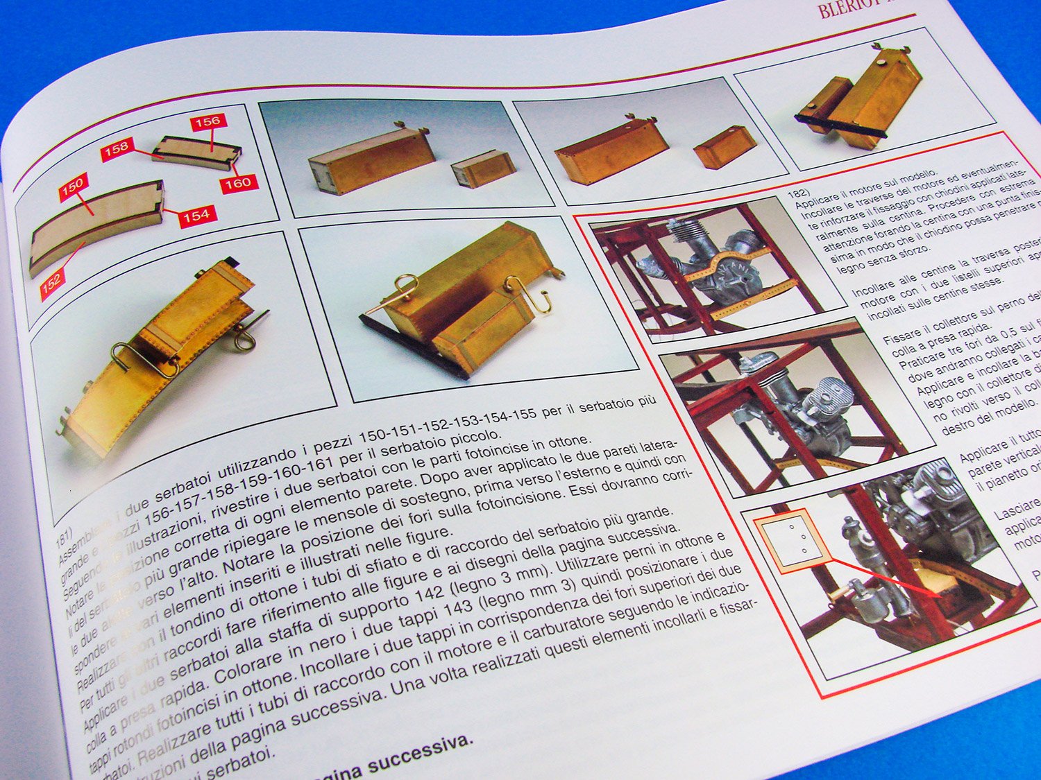
As always, Amati’s instructions are excellent and productions all of their own. This 62-page A4 (landscape format) manual is produced in full colour with photographs that describe the various stages, step by step. Whilst the text is in Italian, there is an English translated sheet for those who need it. As well as photographs, a series of illustrative drawings helps the modeller throughout, and everything is also annotated superbly. A parts list is supplied here, as it on the English translation.


Two plan sheets are included with one of these depicting various views of the Blériot for constructional reference, and also a sheet with plan parts supplied. These can be married up against the unnumbered parts on the laser-cut sheets.
Conclusion
Despite the minimalistic look of the Blériot, this isn’t a weekend project, by any means. There is still going to be a concerted effort needed, as with any model whose main assembly is in timber. Overall, the skeleton of the model is actually straightforward and only minimal tools will be required. Some care will be needed in covering the wings and tailplane, and you may opt to use an antique style material which is used for covering flying model aircraft wings and applied with an iron. Overall, the timber parts are superbly cut with little scorching, and the numerous PE sheets/frets will keep you entertained for many hours, as will those wheels which are built up from individual spokes. If you are a super-detailer, then you could also rig the fuselage with wire and use reproduction turnbuckles, instead of the supplied rigging cord. There are many possibilities, should you wish to deviate from an already excellent kit. You will need a large area to display this model, or it could hang from the ceiling in your study, recreating those stylish days of yesteryear. This kit is also very reasonably priced, so if those memories of the Flambards TV series or the original books by Kathleen Peyton etc. are what fire your imagination, give this kit a shot!My sincere thanks to Amati for sending the kit you see under review here. To purchase directly, click the link at the top of this article.

- Archi, thibaultron, Canute and 14 others
-
17
-
If you can hold off a couple of years, then the Amati Victory looks like a good proposition
")
-
Just now, VTHokiEE said:
I've had my eye on this building slip since I saw this review (really, it is over kill for me but I was concerned that I would "quickly" outgrow the smaller version ), but I live in the US and almost all the locations that I saw for the slip were in Europe and due to the size of the slip shipping costs became something of a non-starter. Recently I emailed hobbyzone to inquire about their shipping costs and they directed me to http://www.hobbyworld-usa.com/. The banner of the website triggered my spidey-sense, so I asked my wife to order it for me instead for a birthday gift (😉). It arrived a few weeks ago and today I finally celebrated my birthday and opened the slip. I still have to put it all together, but I wanted to let anyone in the USA who is interested know where you might find it.
Great stuff!
If you want to add to this topic by showing a few photos on how you use it with your model, feel free.
-
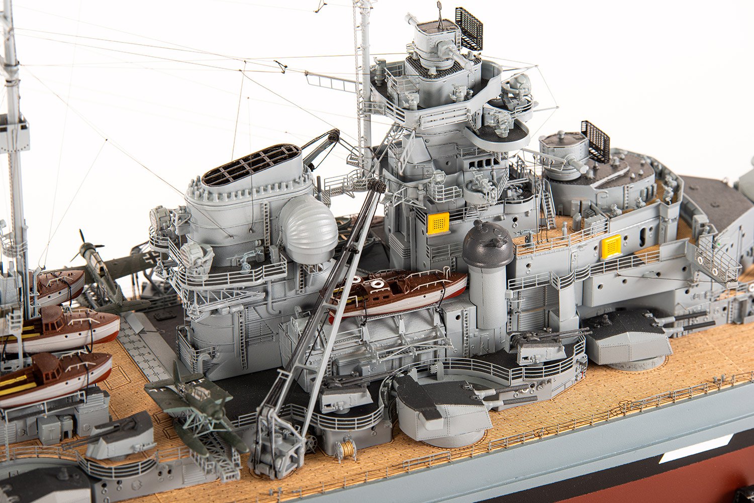
On 12/1/2019 at 5:04 PM, Bobbuild said:
Any update?
Still waiting on the laser stuff and PE/cannon. I do have the 30+ sheets of plans already.
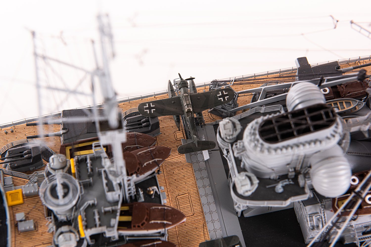
The Bismarck kit had to be prioritised for Nuremberg toy fair in late Jan, so I expect the parts will be sorted for me very soon.
- mtaylor and paulsutcliffe
-
2
-
This is just outstanding. Your planking is quality. What a great job 🤗
-
-
-
-
-
...a few more!

-
If you mean plastic kits, then the very best is Tamiya Extra Thin Cement. You can put the parts together as apply a little with a brush to fix things. This includes long seams. I use it all the time for my magazine work.
Now, if you are also talking RC models, then that may be a different plastic and not styrene. I would look at both Cyanoacrylate (superglue), with Zap being an excellent brand, and also epoxy. It all depends on the specific task you are performing.
-
That looks superb! I always wanted to try one of these kits.
- popeye the sailor, druxey, Canute and 2 others
-
5
-
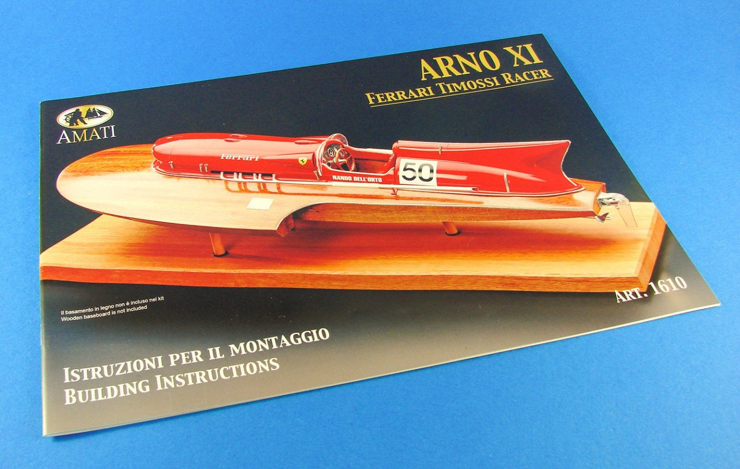
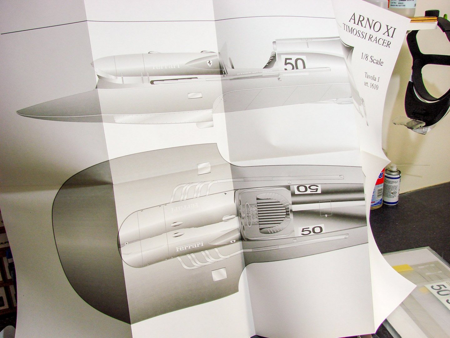
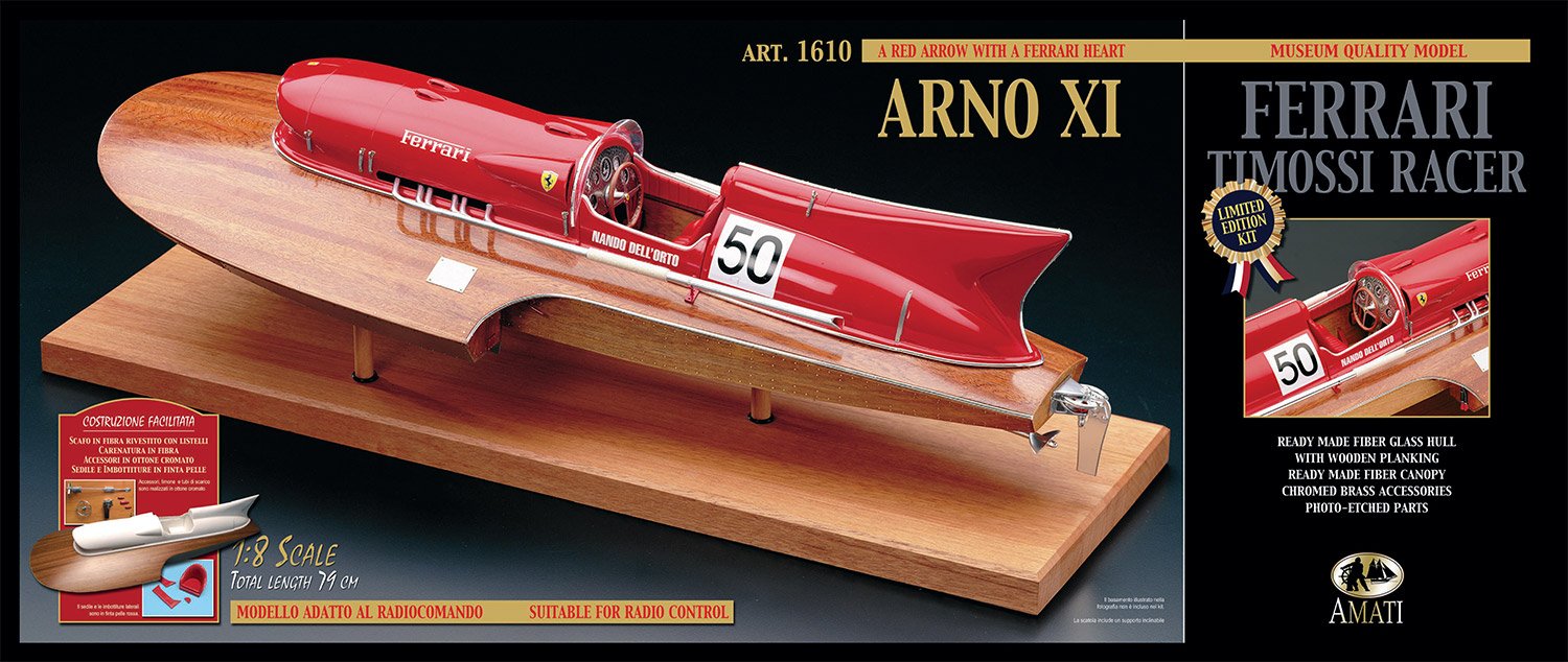
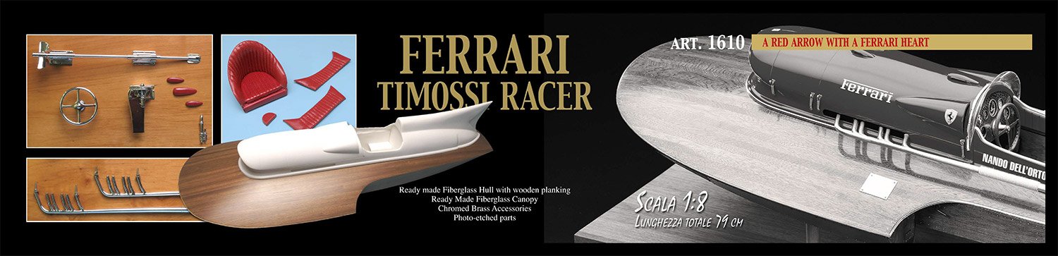
1:8 Ferrari Timossi Racer ‘Arno XI’ (Special Edition)
Amati Model
Catalogue # 1610
Available from Amati for €319.67, excluding tax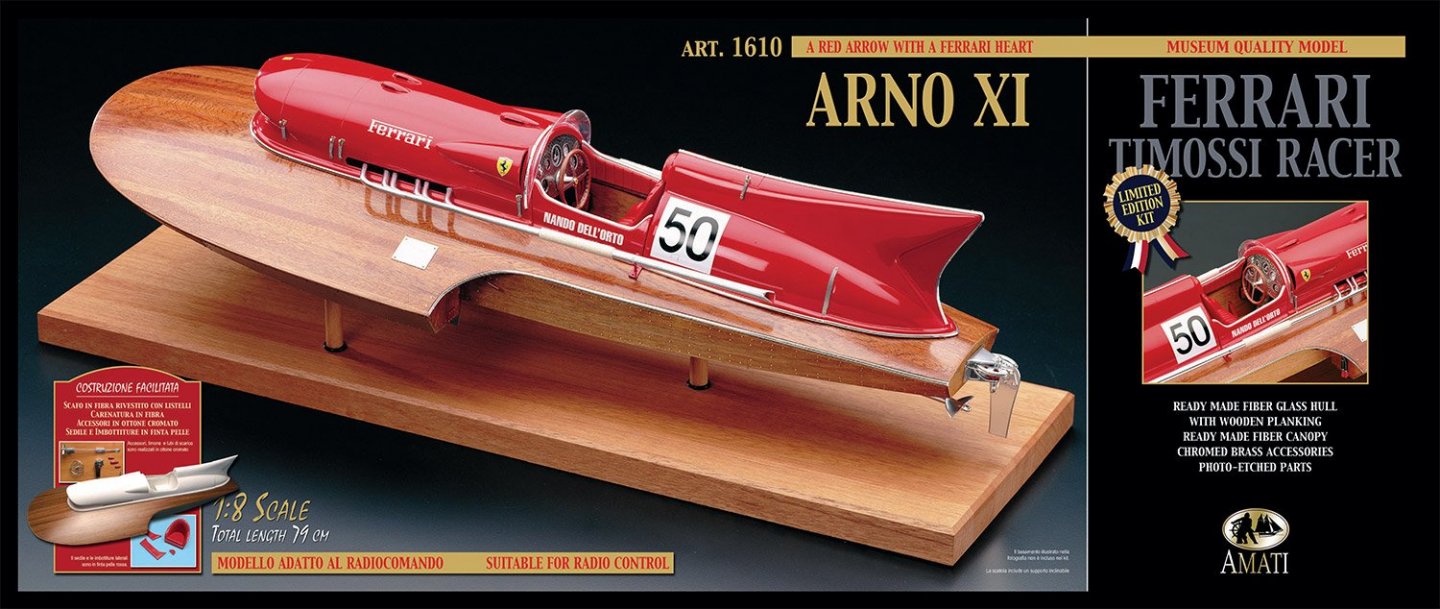
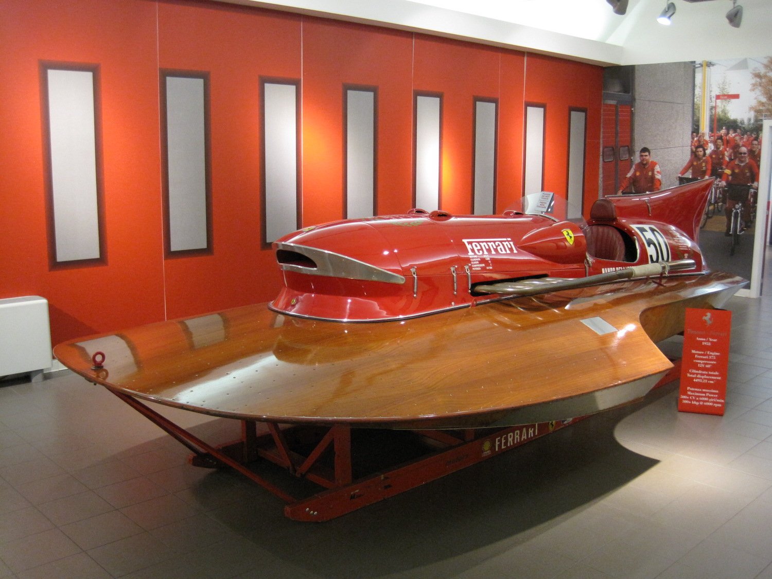
The Arno XI is a hydroplane inspired by Achille Castoldi in the early 1950s and built by the Cantiere Timossi boatyard, located in Azzano (a frazione of Mezzegra) on the Lake Como. Castoldi wanted to establish a world water speed record so he persuaded then Ferrari racing drivers Alberto Ascari and Luigi Villoresi to influence Enzo Ferrari to supply him with a 4.5-litre, V12 Ferrari engine; the same engine that gave Ferrari his first Grand Prix victory with the Ferrari 375 F1 at Silverstone Circuit in 1951. The engine was installed in a Timossi three-point racing hydroplane hull. Castoldi managed to further increase horsepower by attaching two superchargers. The result was a 502 bhp speedboat, which he used to hit a 150.19 mph top speed in October 1953 on Lake Iseo.

This world speed record for an 800 kg boat still stands today. Arno XI was later sold and raced in numerous competitions, finally retiring in 1960. It has since been restored and as of December 2019, is expected to go for up for sale by RM Auctions for up to €1.5m.
Information and photo taken from Wikipedia
The kit
The Arno XI is far from a new release, with the original kit first seen around the 1990s. That specific release is still available and has a traditional built-up hull that the modeller must plank with the supplied strip wood. I have seen one of these built up in a model shop in Manchester, UK, a good number of years ago, and it was outstanding! When Amati asked if I would like to take a look at the newer version of this kit, in Special Edition format, I really couldn’t refuse. What makes this kit different to the original is that the entire hull is pre-built in glass fibre. If that’s not enough, then it’s also pre-planked in mahogany and polished too! With the cockpit superstructure already being a fibreglass composite component, then this model is as close as you can get to the hard stuff being done for you. It’s also suitable for Radio Control (RC), and measures in at an impressive 79cm.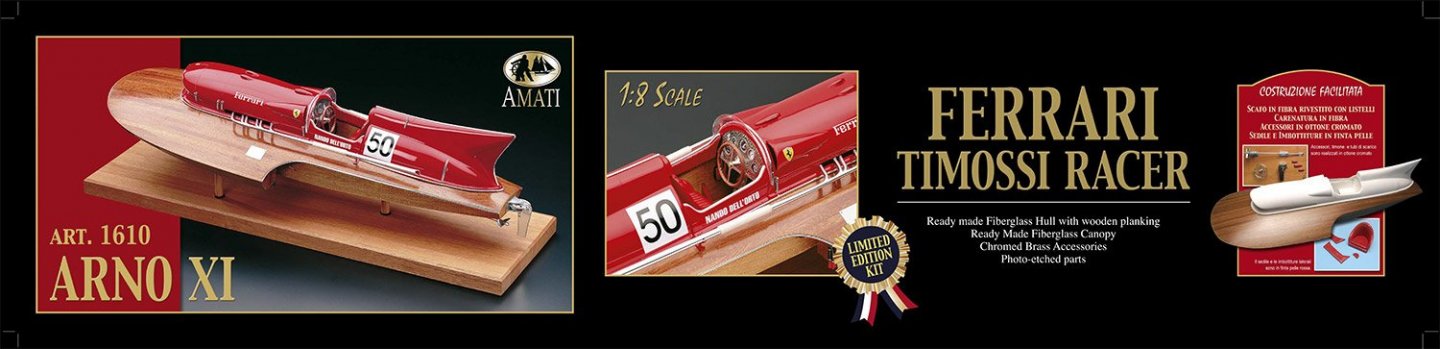
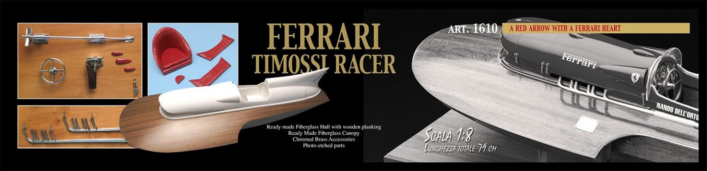
Now, this box is large and reasonably heavy too. A glossy sleeve envelopes the box, with a large image of a completed and mounted model, resplendent in the famous Ferrari red. The box sides show images of the box contents, and most impressively, that pre-built hull. But, what does it actually look like? OK….here goes.
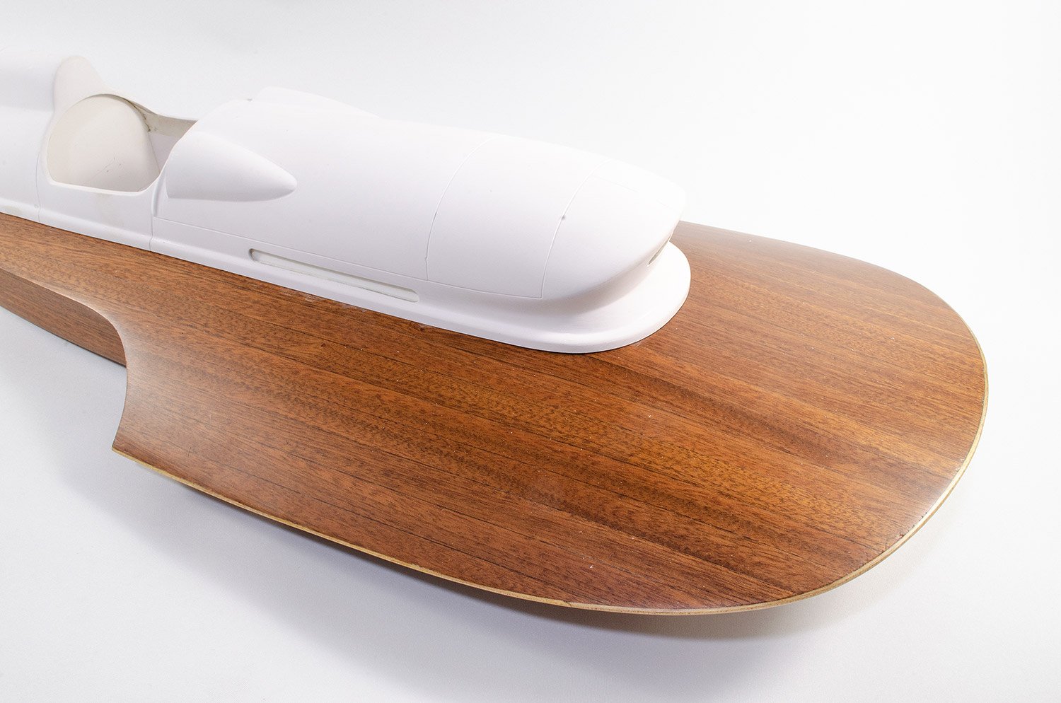
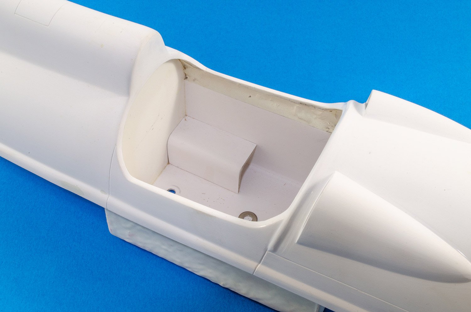
Removing that sleeve is amazingly difficult as the fit is so tight. It took both myself and my wife to extract it without causing it damage. With that carefully removed, the tabbed box lid was opened to reveal the contents. Of course, I knew what I was going to see, but actually seeing it was something else! The pre-built hull is absolutely stunning. Amati has carefully packed this so that the other elements such as boxed components and manual, cause no damage to the beautiful finish of the main model. The cockpit/engine superstructure, is also sat in situ, giving a real impression of how this model will look once complete.
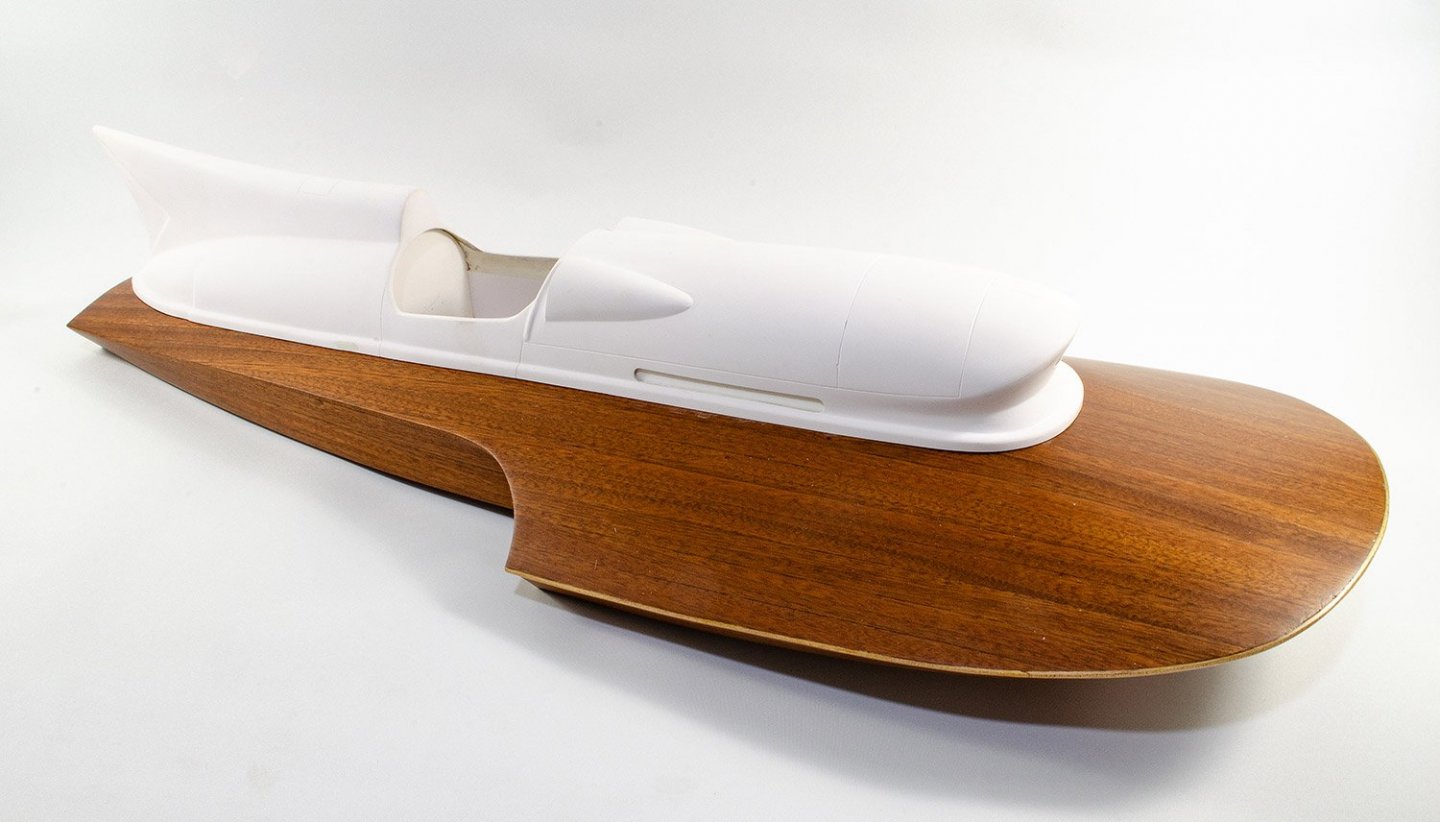
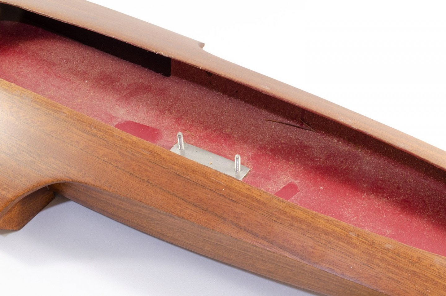
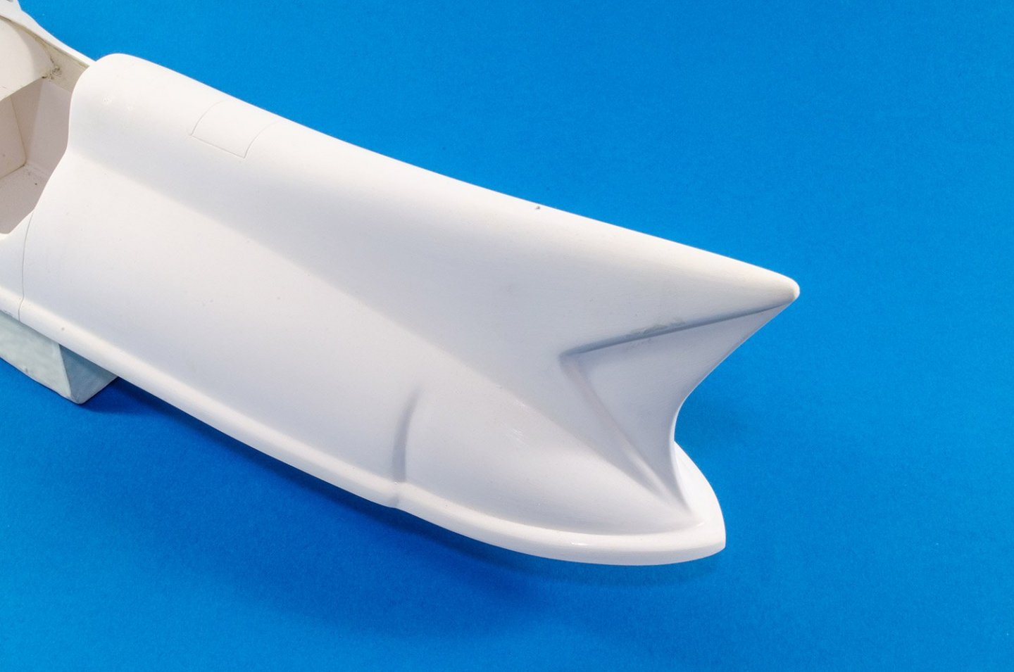
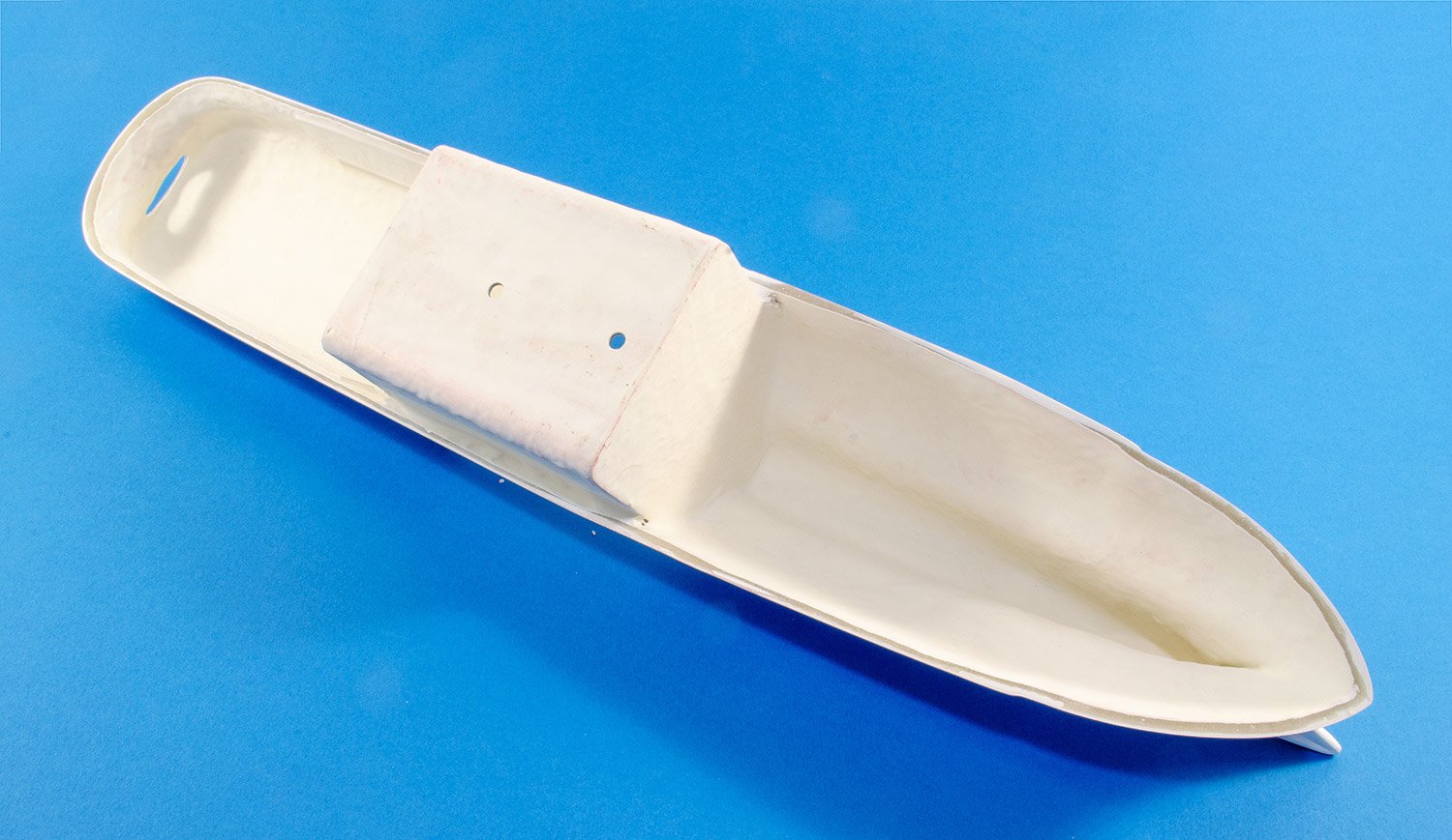
With all of the packing components removed, the hull is now lifted from the box. There’s quite some weight in this, but probably not much different to how the traditional construction hull would weigh. In fact, this could be a tad lighter, dependent on the thickness of the glass fibre moulding. A quick check around the exterior showed that there were no real causes for concern regarding the finished quality of this and the safe shipping of it to get to me in the UK. Hull planking is extremely high quality, with nice, tight grained mahogany creating that famous finish. The whole surface is also very smooth. In fact, the only thing that you might do to finish that aspect is to give it a final coat of high-gloss varnish instead of the satin/low-gloss finish the model comes with. There will be some smaller details to add to the timber finish such as metal edging and brass nails. We’ll look at those soon. For the moment, I now remove the superstructure and look within the hull. The is secured by two nuts which fit to bolts that are secured into the bottom of the hull. One quick note here is that the hull interior or quite dusty from the manufacturing process, and I suggest the use of a mini keyboard hoover and a damp cloth to totally clean out the interior before you continue with any sort of paint or varnish work.

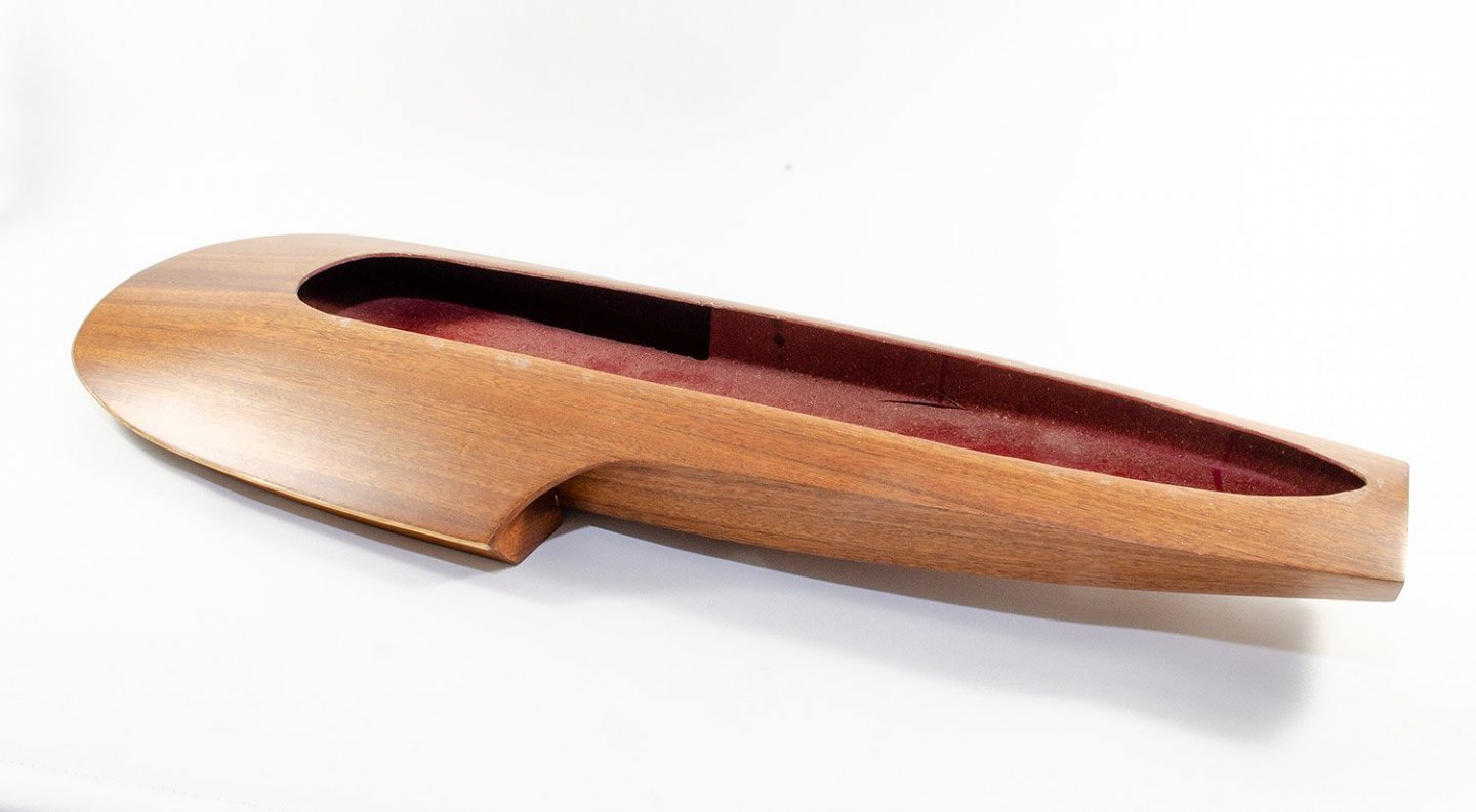
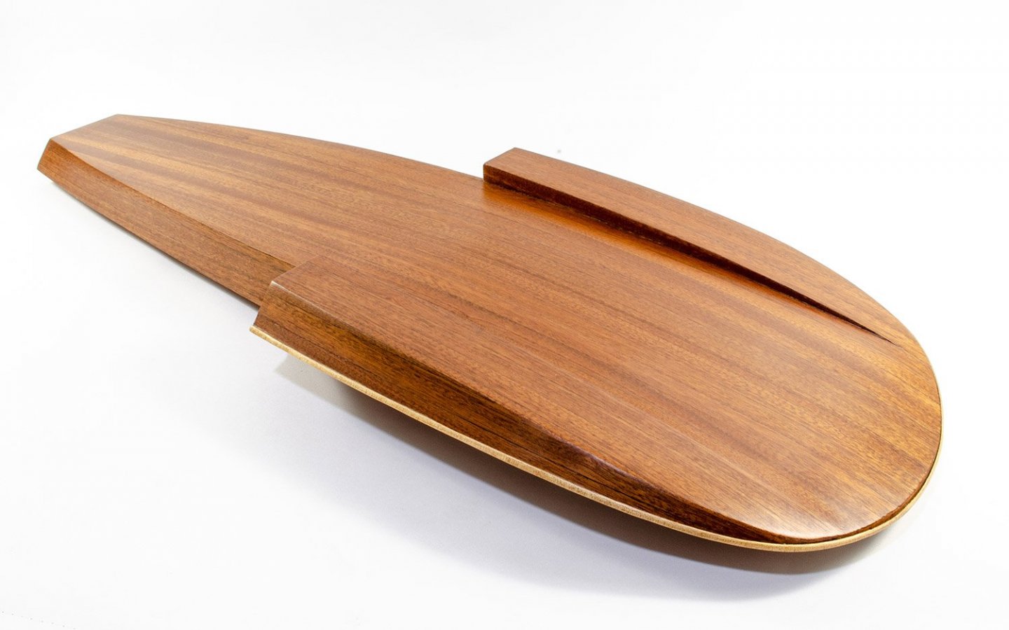
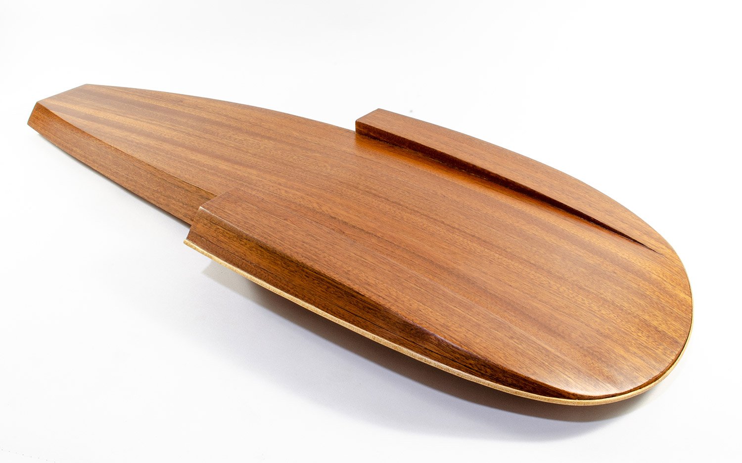
That extremely nice mahogany planking extends to the undersides, despite the fact that some of this will of course be sheathed by large pieces of photo etch metal.
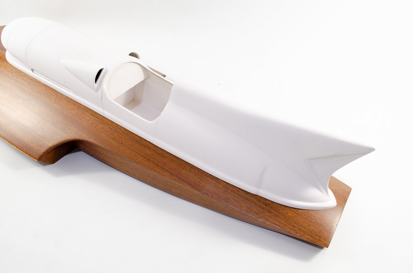
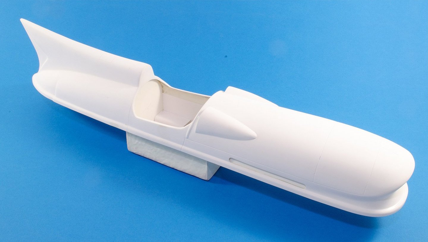
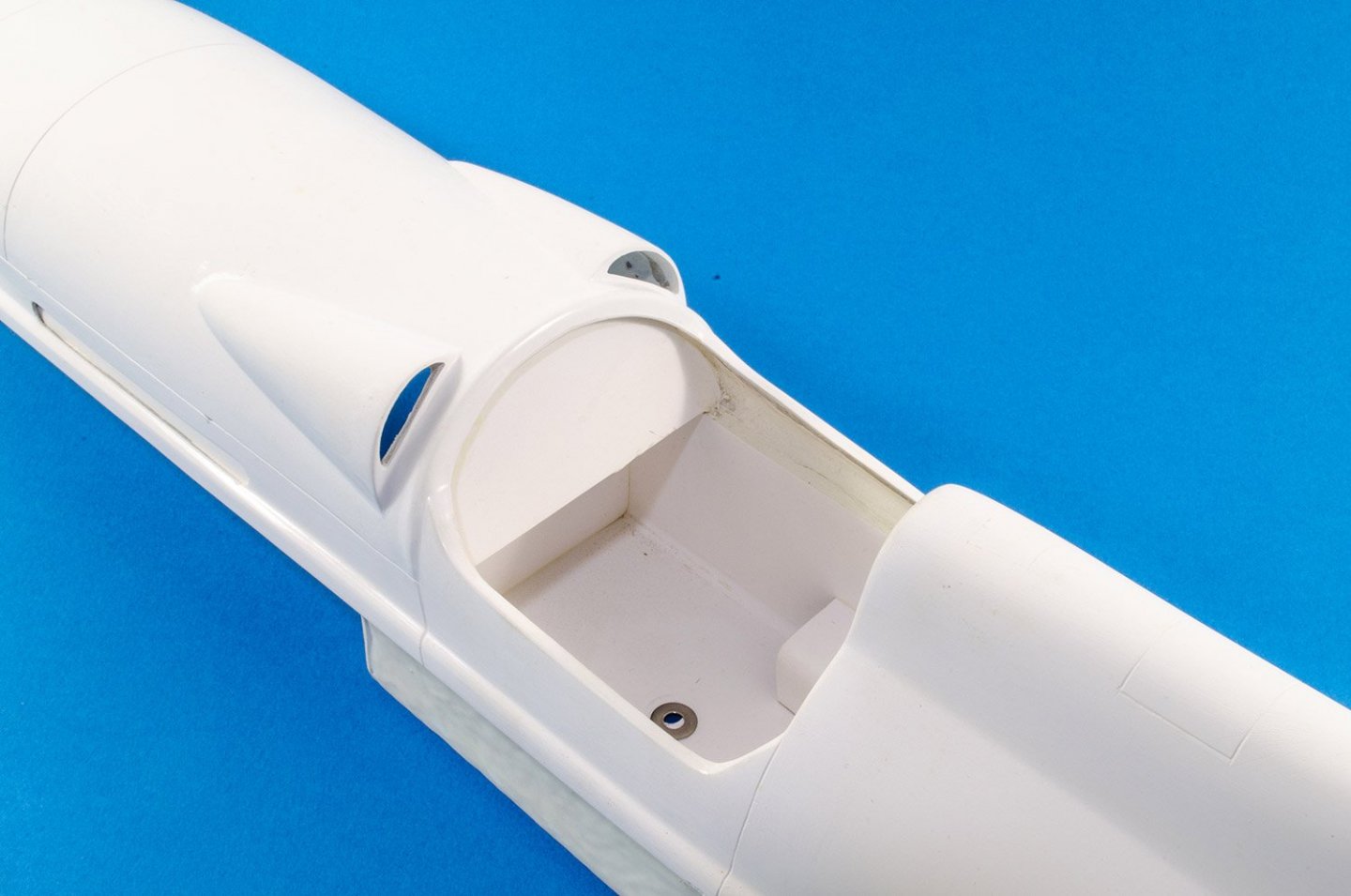
The superstructure is also comprised of glass fibre sections which have been carefully assembled and have a very smooth external finish. The external details include nicely even engraving for panel lines. The bare cockpit will be fully fitted out in some superbly sumptuous fittings, as we’ll shortly see. Here, you can clearly see the fibreglass box which forms the bottom of the cockpit. The superstructure itself is also quite weighty. Some very minor clean-up will be required before work commences.
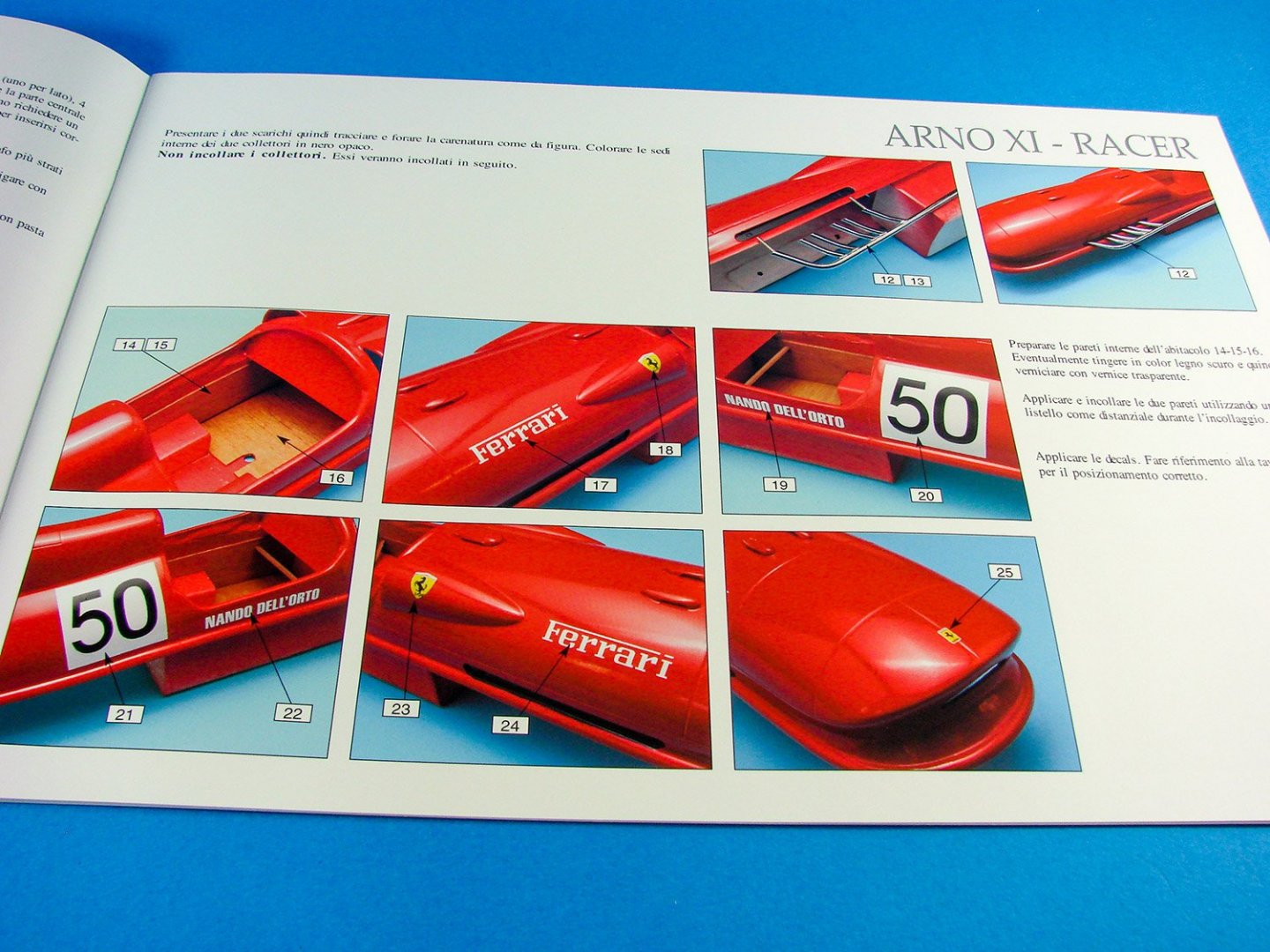
Here, you can see the interior of the basic cockpit, with the holes/washers that fasten the superstructure to the lower hull. The box units that are built into the walls, will support the upholstered chair. You will need to make the seat removable, should you every wish to be able to remove the superstructure for the RC model version. For static, it isn’t necessary. Also of note here is that this release doesn’t detail how you would fit this model out for RC, but for an enthusiast, I can’t see it being too much of a problem as the interior of the superstructure and hull are quite easy to work within, being very accessible.

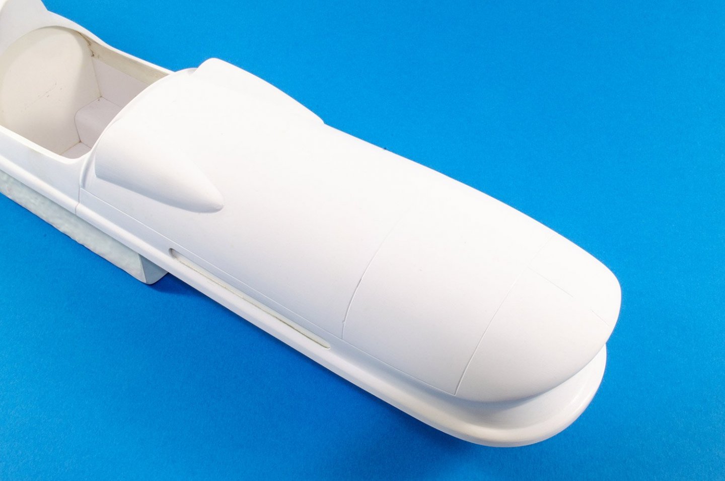
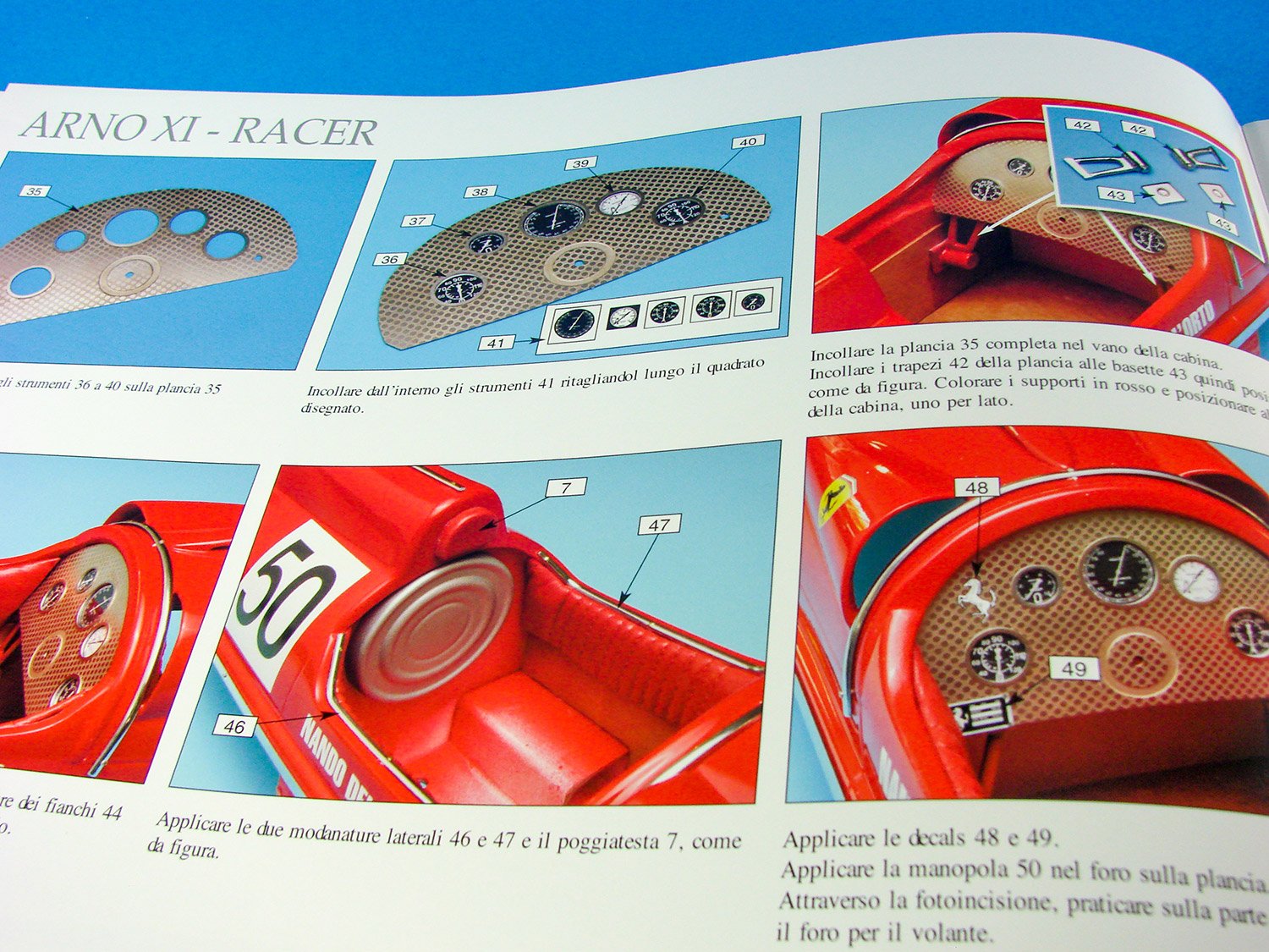
An instrument panel is also fitted into the cockpit as a base for the detailed unit which will sit atop this. You’ll see that the vents just in front of the cockpit will also need to be cleaned up before you start to paint the superstructure. Now, if you know someone who works in an automotive garag and can persuade them to give a perfect Ferrari red finish to this unit, then that would be even better than using hobby paints, as a good two-part epoxy paint finish would really set this model off.

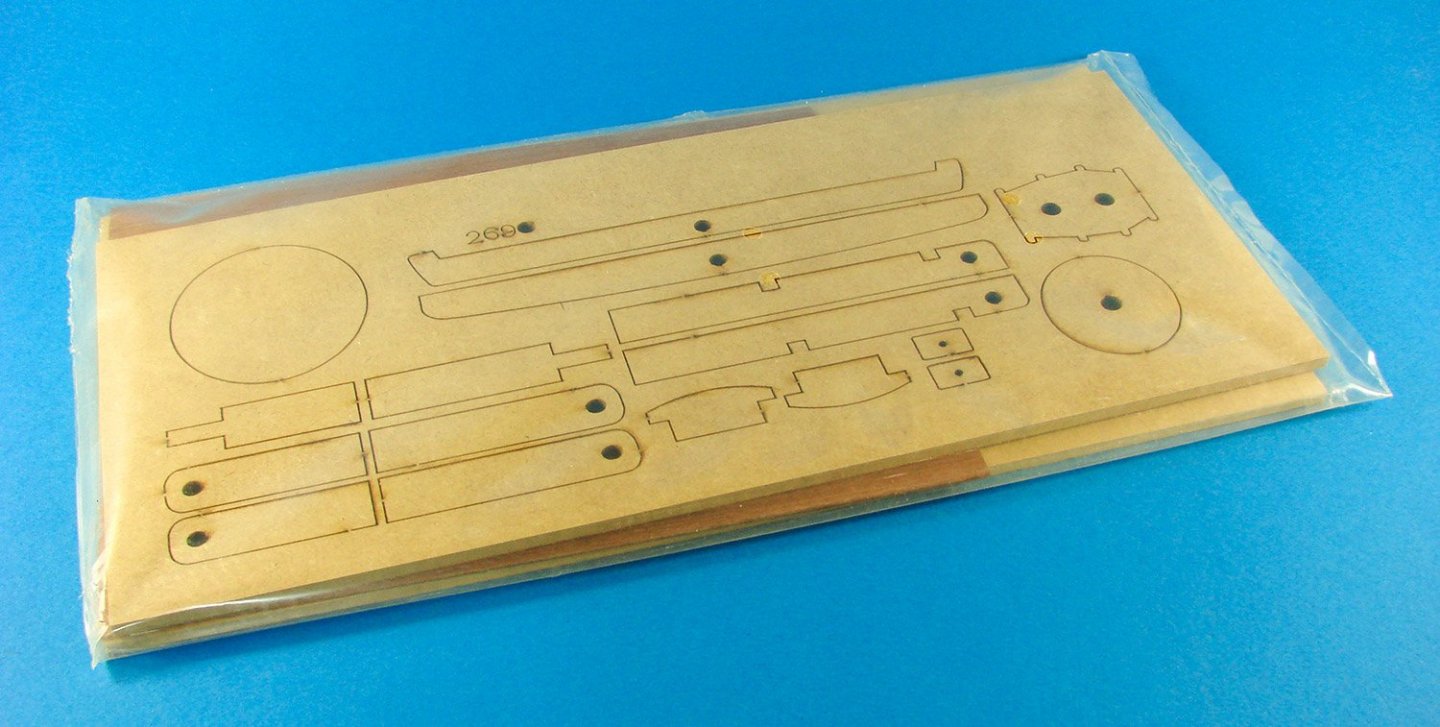
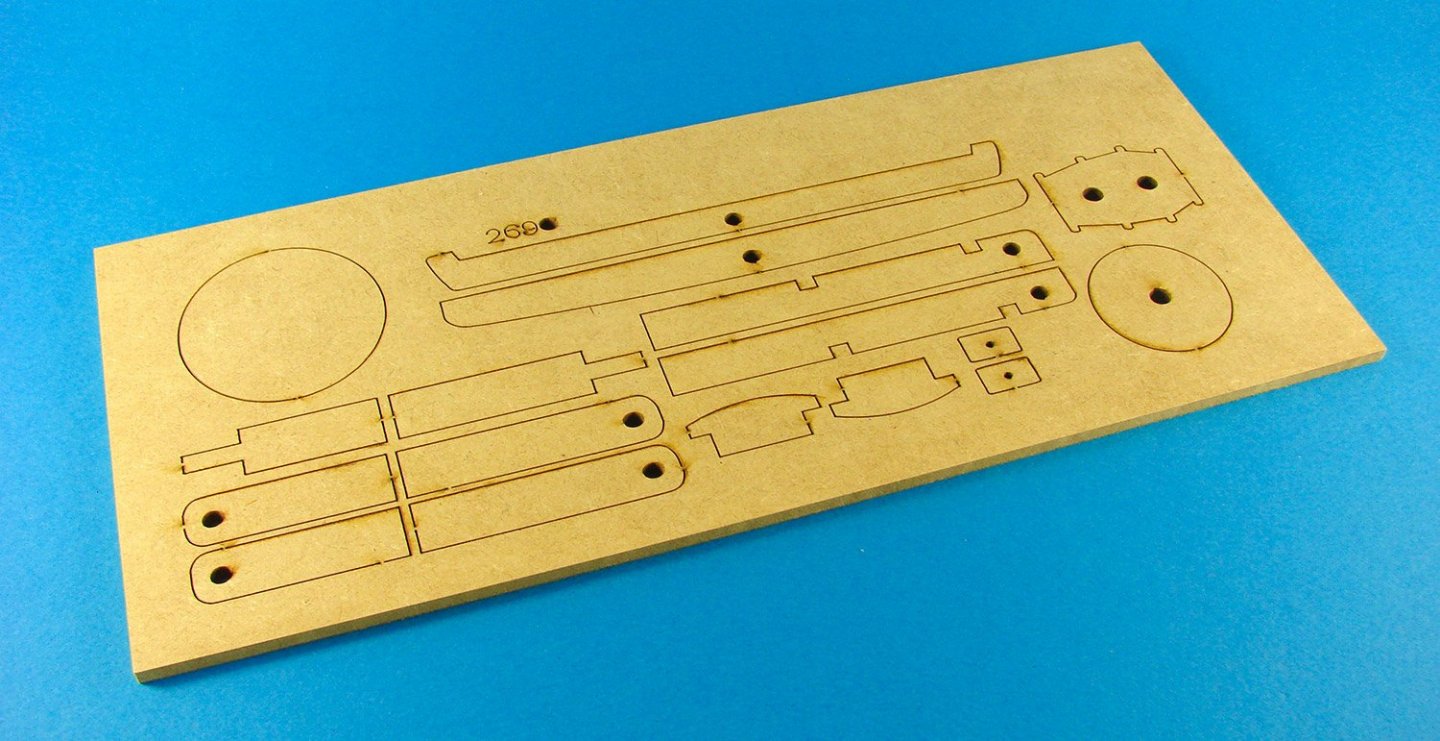
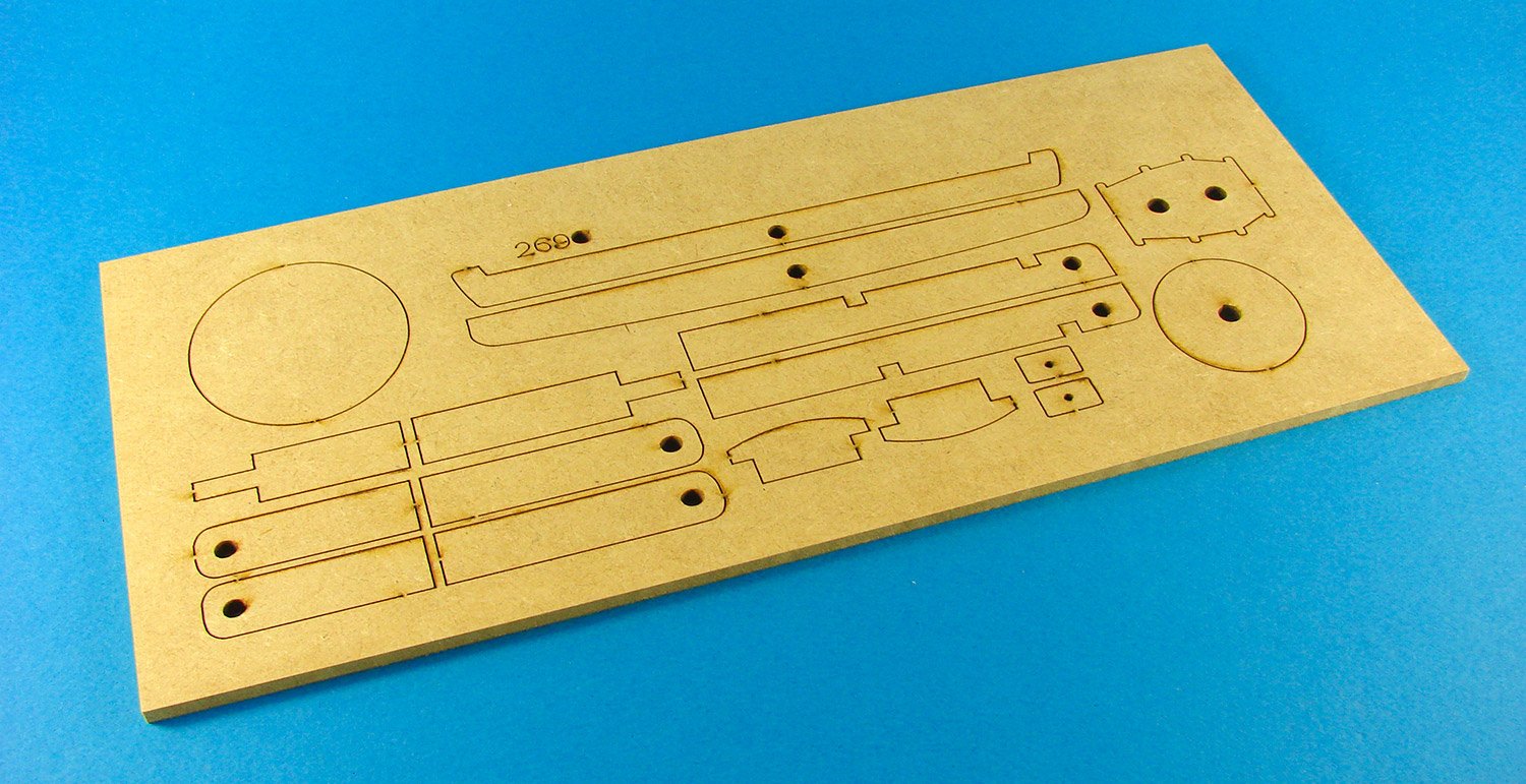
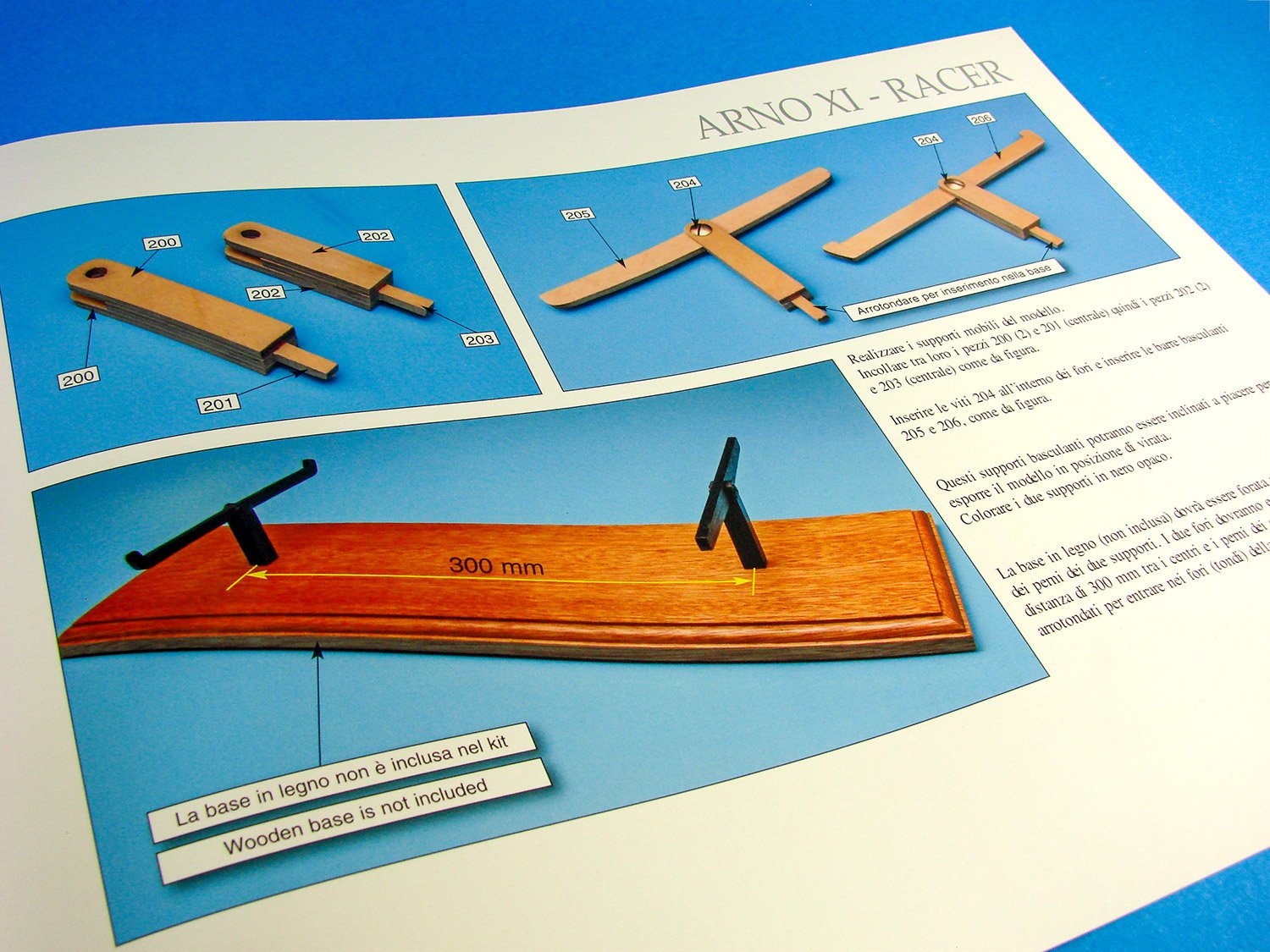
Lying underneath the tail of the hydroplane hull is a touch cellophane sleeve that contains three sheets of material (MDF and mahogany veneer). This first sheet contains a couple of cores and frames for some cockpit detail work, but also has a number of parts for what will form a cradle for holding the completed model. These will need to be secured to a long wooden plinth, set 300mm apart, but this plinth is not included in this release, so you’ll have to check out your favourite hobby outlet. Laser cutting is very good, within fine cuts and minimal scorch.
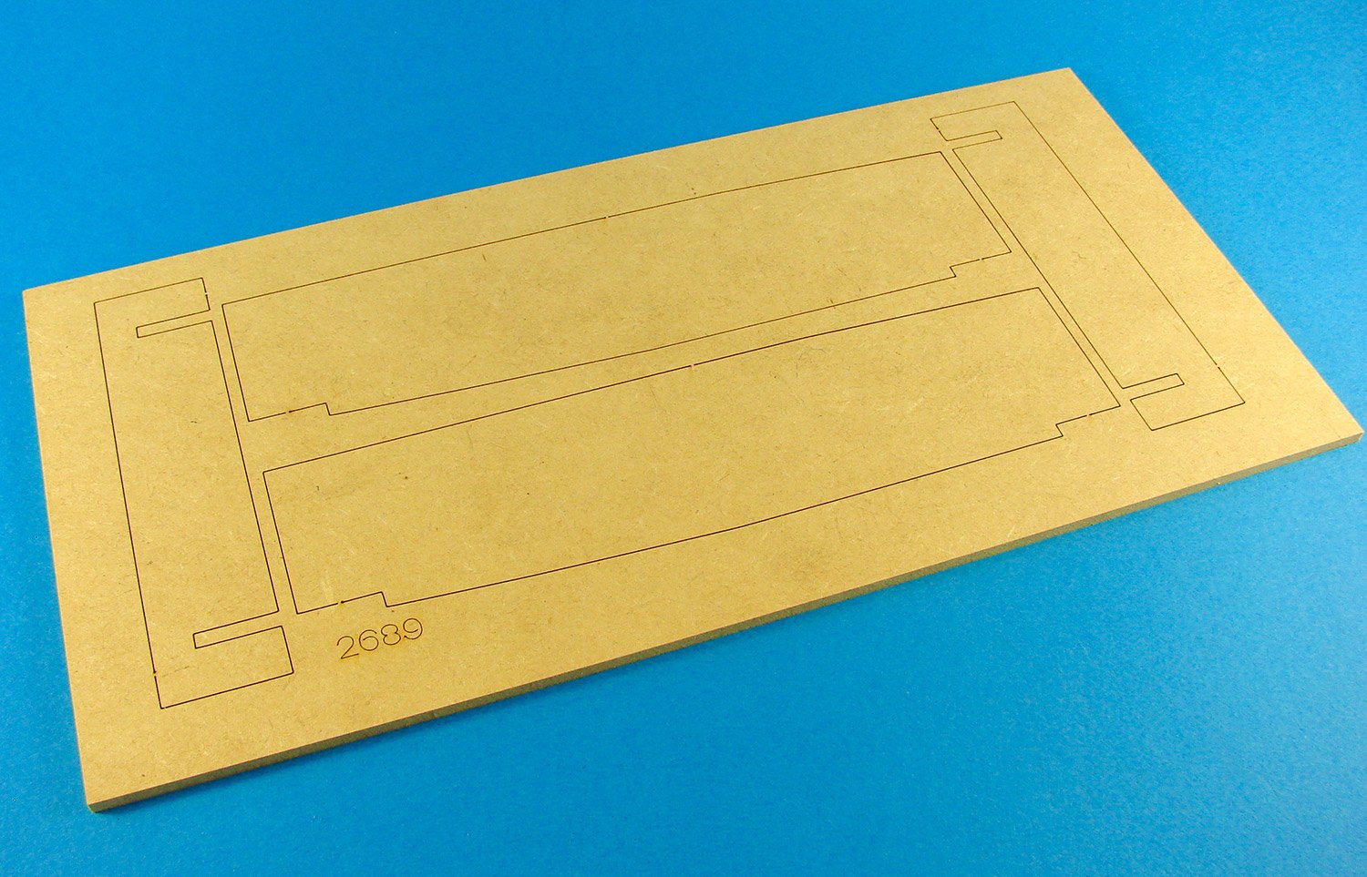
This next sheet contains parts that will be fitted within the hull, around the box area for the cockpit. The idea here is to provide mid-hull rigidity and stop the modeller from over-tightening the superstructure mounting nuts and compressing the fibreglass/timber hull too much.

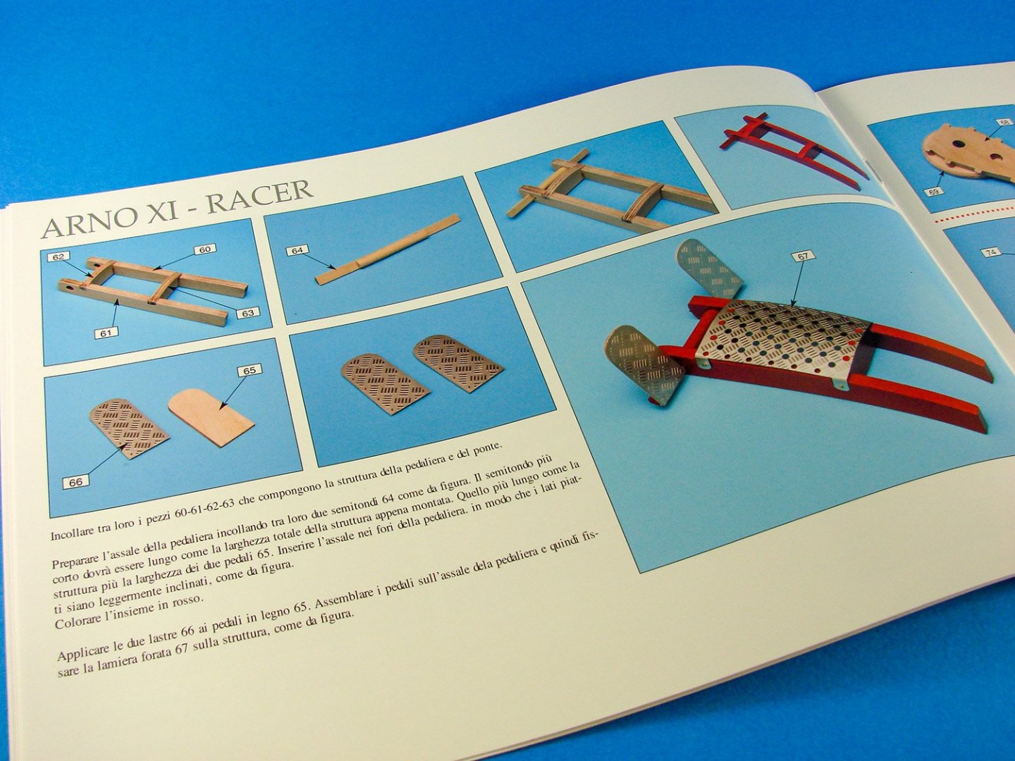
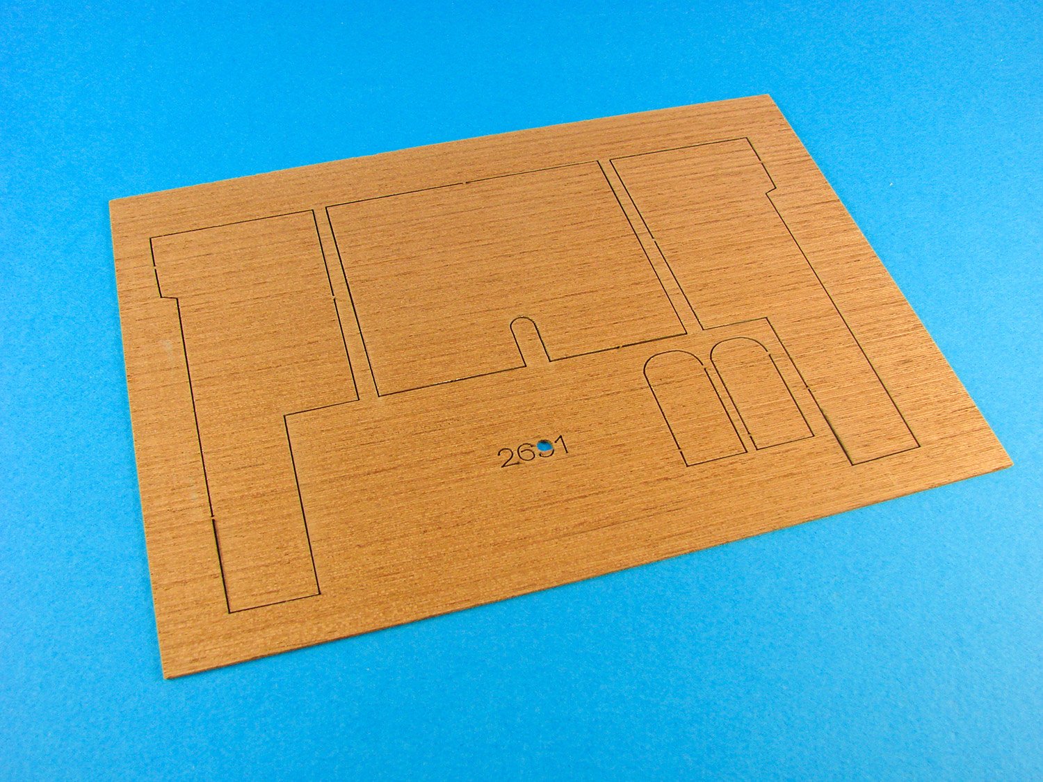
The last sheet of timber is this mahogany veneer. These parts are for the lower cockpit side walls, cockpit floor and also the rear of the pilot’s pedals. Laser cutting is excellent and provides to cause for scorch concern on these decorative parts.
Tucked away in the main packaging jigsaw is this box of components.
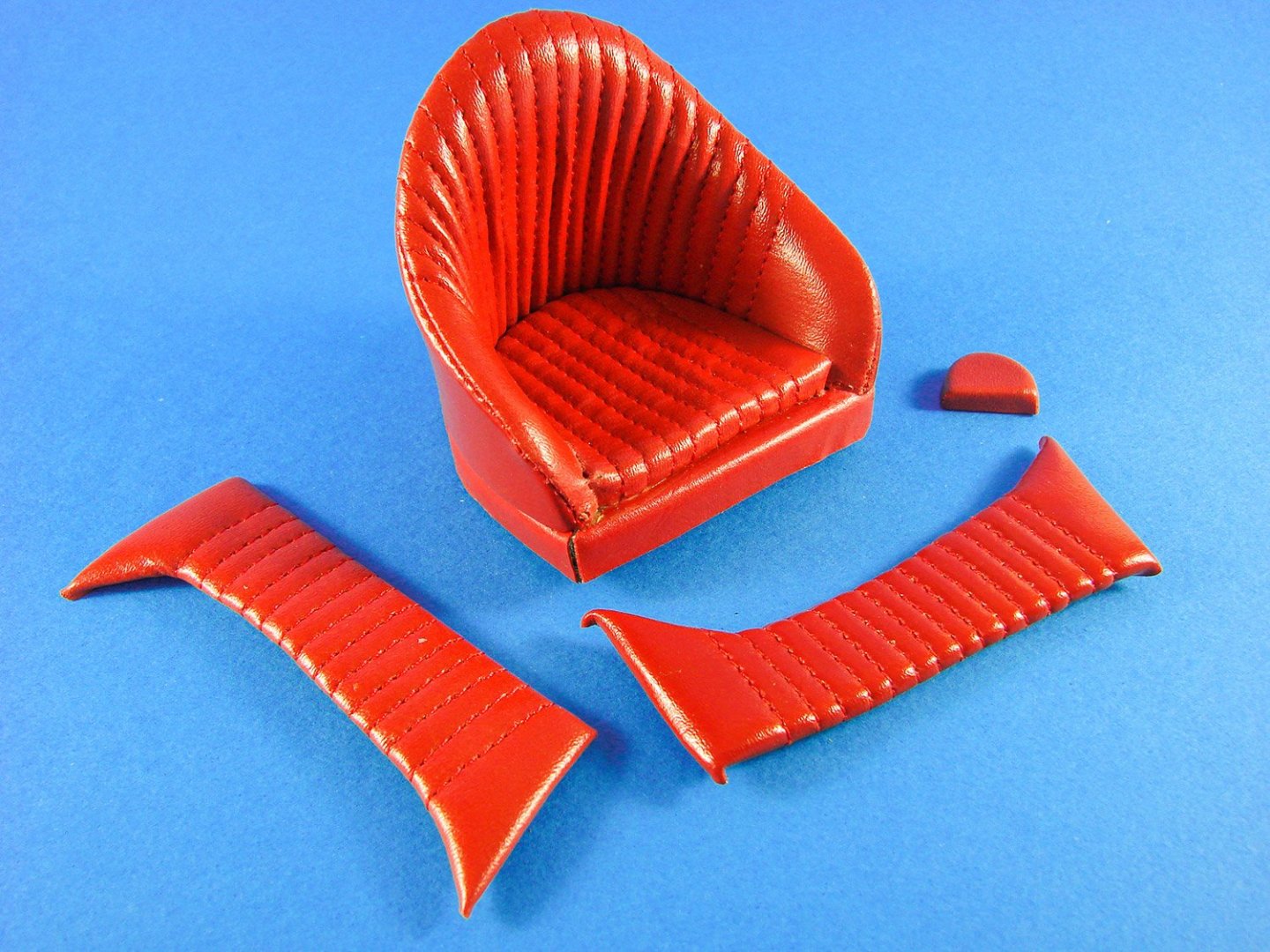
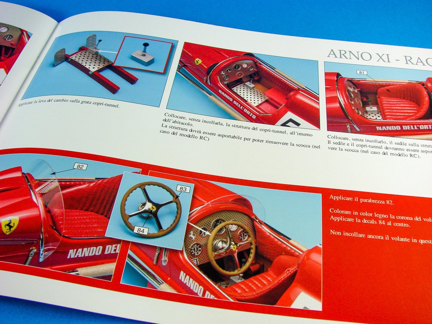
Whilst not actual leather, the seat, headrest and upper cockpit sidewalls are comprised of cores that are hand-stitched with faux-leather and actually look superb! After all, this is a Ferrari! There are standards to maintain…
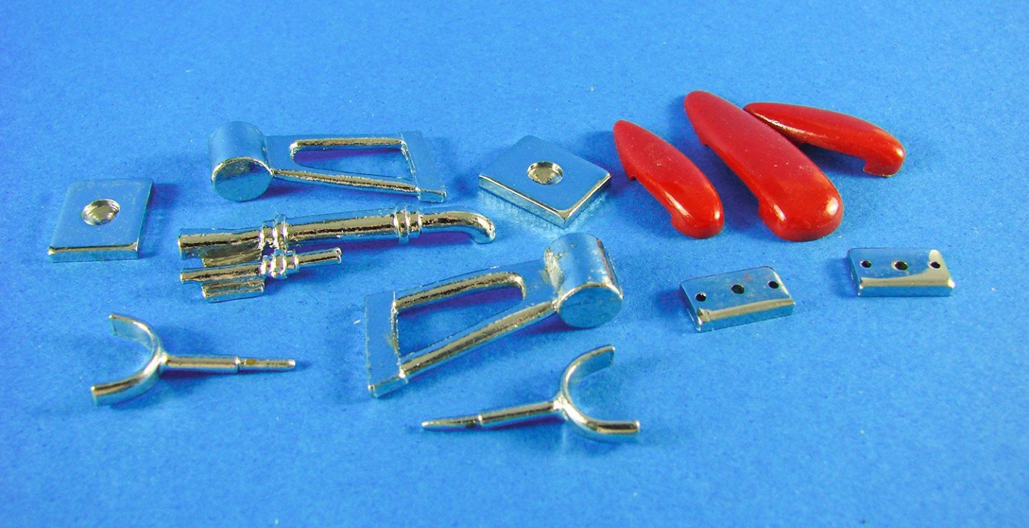
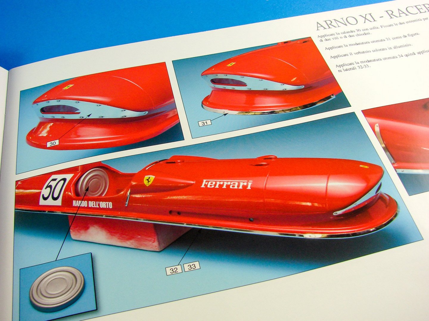
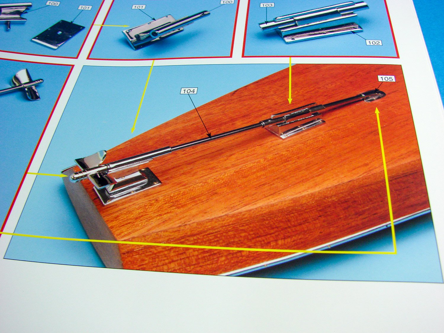
A good number of metal trim parts are supplied, with their chrome finish. The twisted part you see here is actually for the spine of the superstructure, also running down the back end of the tail. You are advised to check these against the unpainted unit and adjust if necessary. You really do need these to be fit-perfect when it comes to the painted model. A length of brass rod is also supplied.
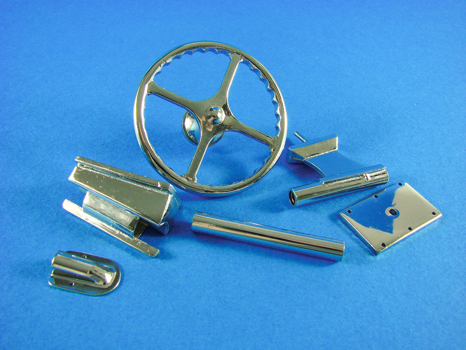
Another bag of parts contains a number of chrome plated metal elements. Here you see the steering wheel and parts for mounting the long propeller shaft on the underside of the hull. All parts are superbly made and have perfect plating. No extra work is needed with these.

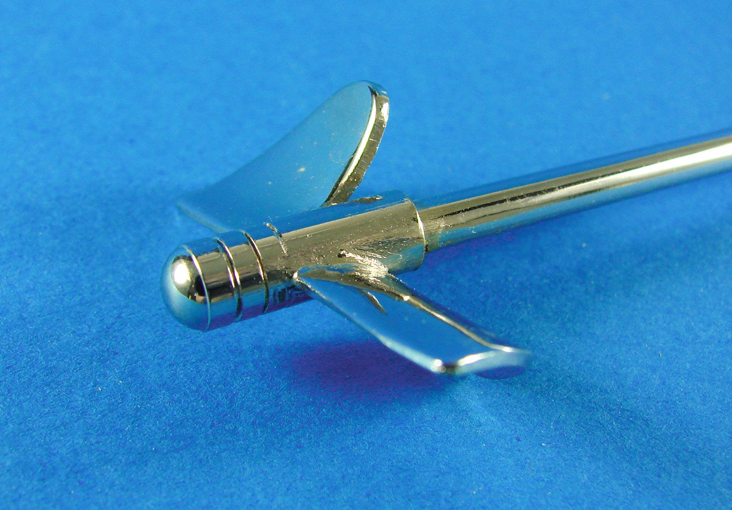
And here is the propeller shaft with integral prop. These will look stunning against the mahogany of the lower hull.
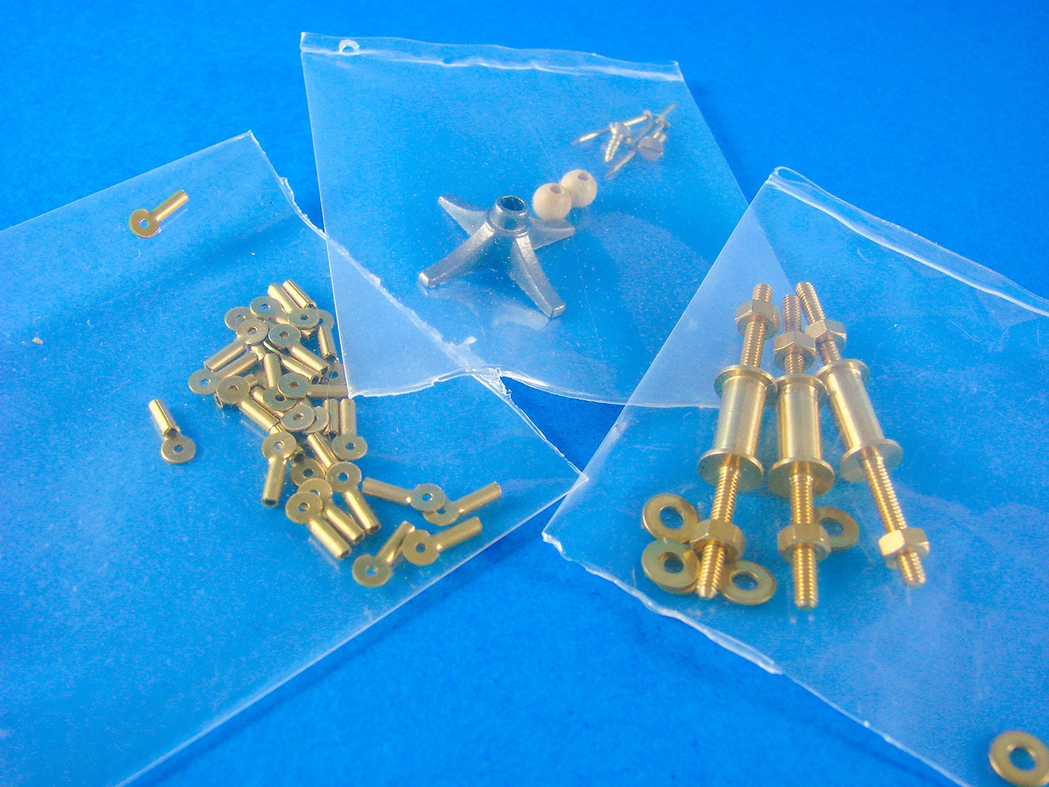
In another bag we have a whole series of parts which will be dispersed around the model. Here, you can see blisters for the upper engine cowls, mounting stirrups for the long exhaust units, pump/syphon unit, and also a small number of cockpit parts.
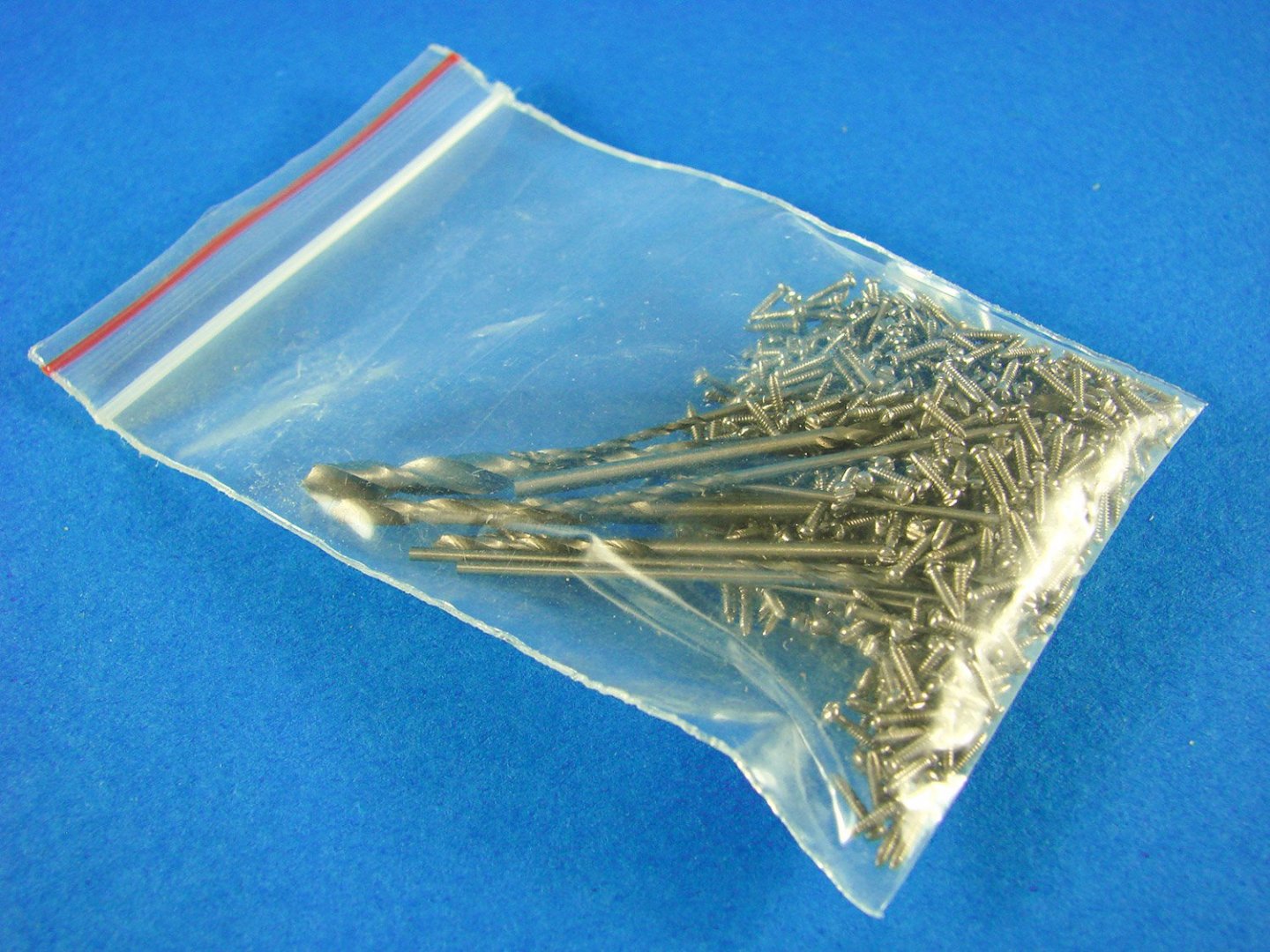
There are a lot of screws supplied with this kit, for various tasks, such as fitting the chrome trims etc. Not only do you get the screws, but there are numerous drill bits supplied to do the job too, ensuring you don’t drill anything with too large a diameter.
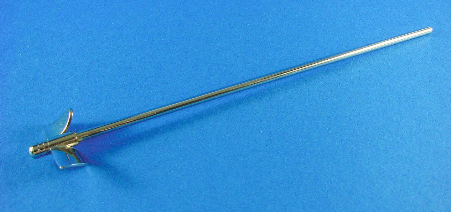
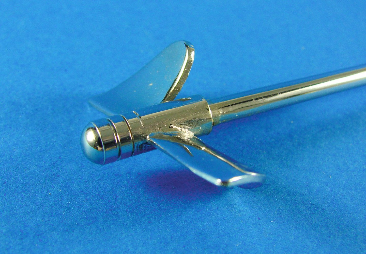
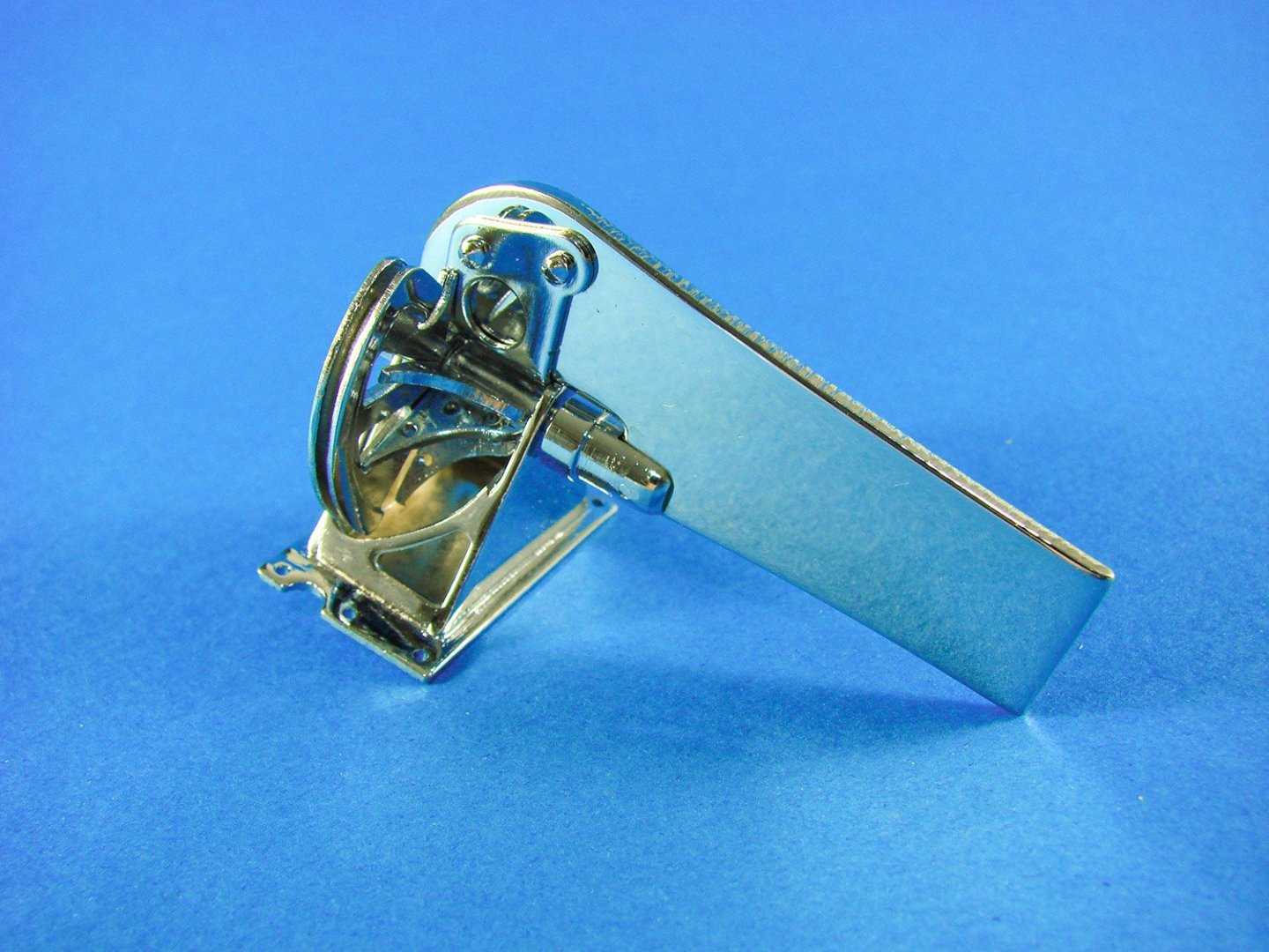
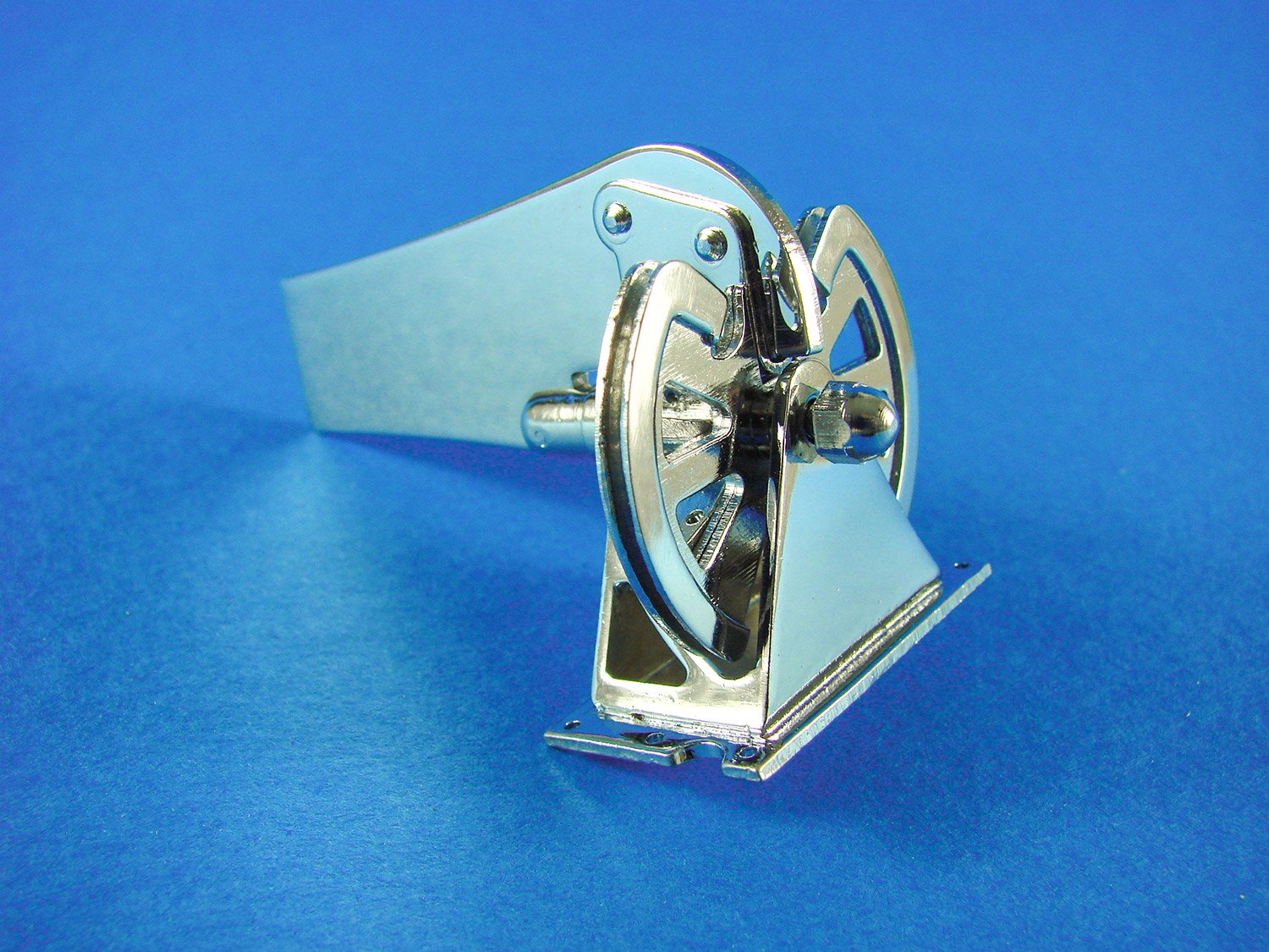
This nifty little unit is the rudder and mounting unit. Constructed from various components, this ready-assembled unit does actually move with a nice, smooth motion. It looks like it’s been made in a Swiss watch factory!

All chrome trims have been pre-shaped. All you need to do is to check them against the hull and superstructure, and tweak if necessary. They are also pre-drilled to accept the fastening screws.

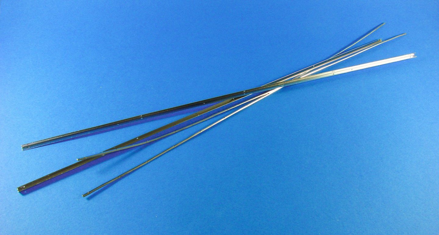
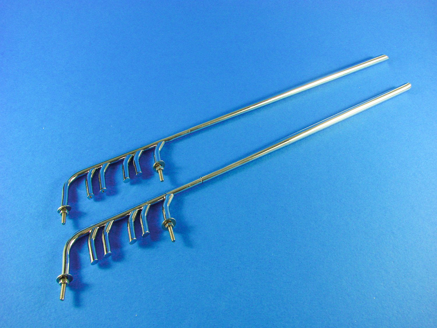
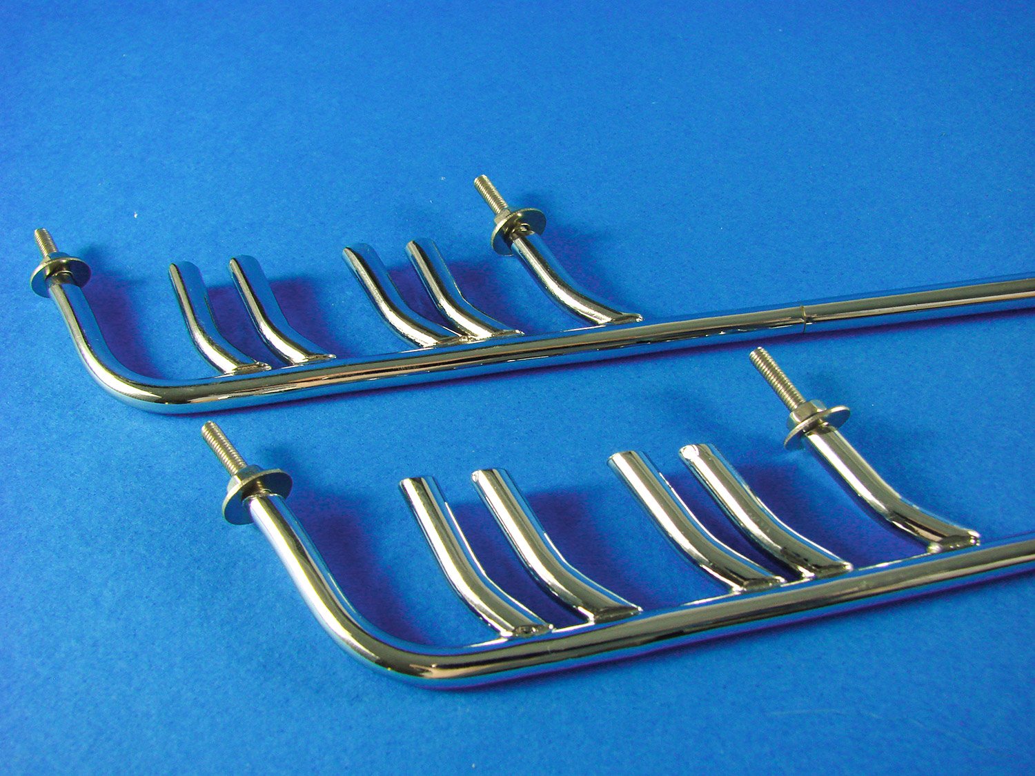
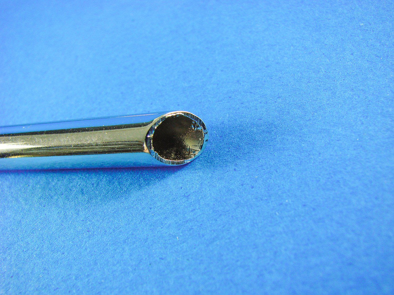
These are the exhaust units, and they are both long and heavy, made from brass and chrome-plated, these units screw to the superstructure engine cowls and also rest on the stirrups that are mounted to the top of the hull. The ends are also hollow for realism.


More trim and décor here!

Yes, there’s another box of parts with a relatively small part’s count.
A photo-etch instrument panel is included, complete with the authentic, vintage finish that’s been pre-etch. Onto this will fit the metal bezels, and acetate/printed instruments will fit from behind.

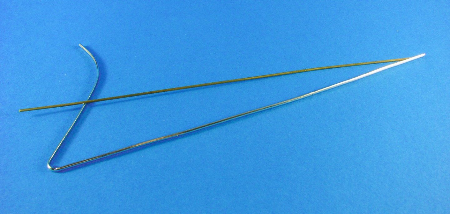
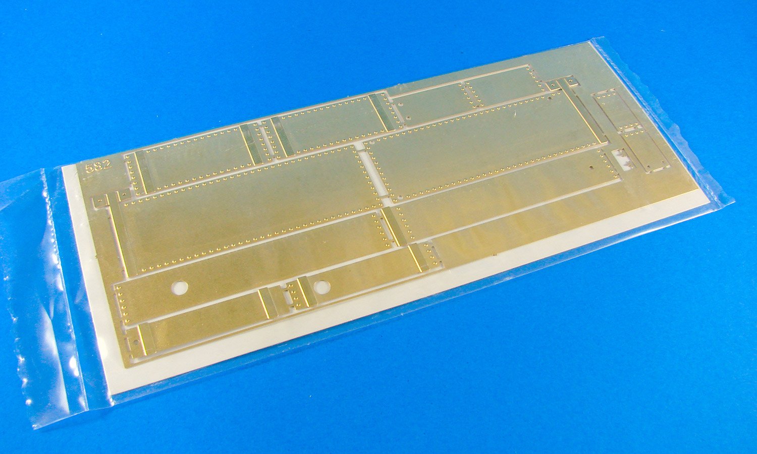
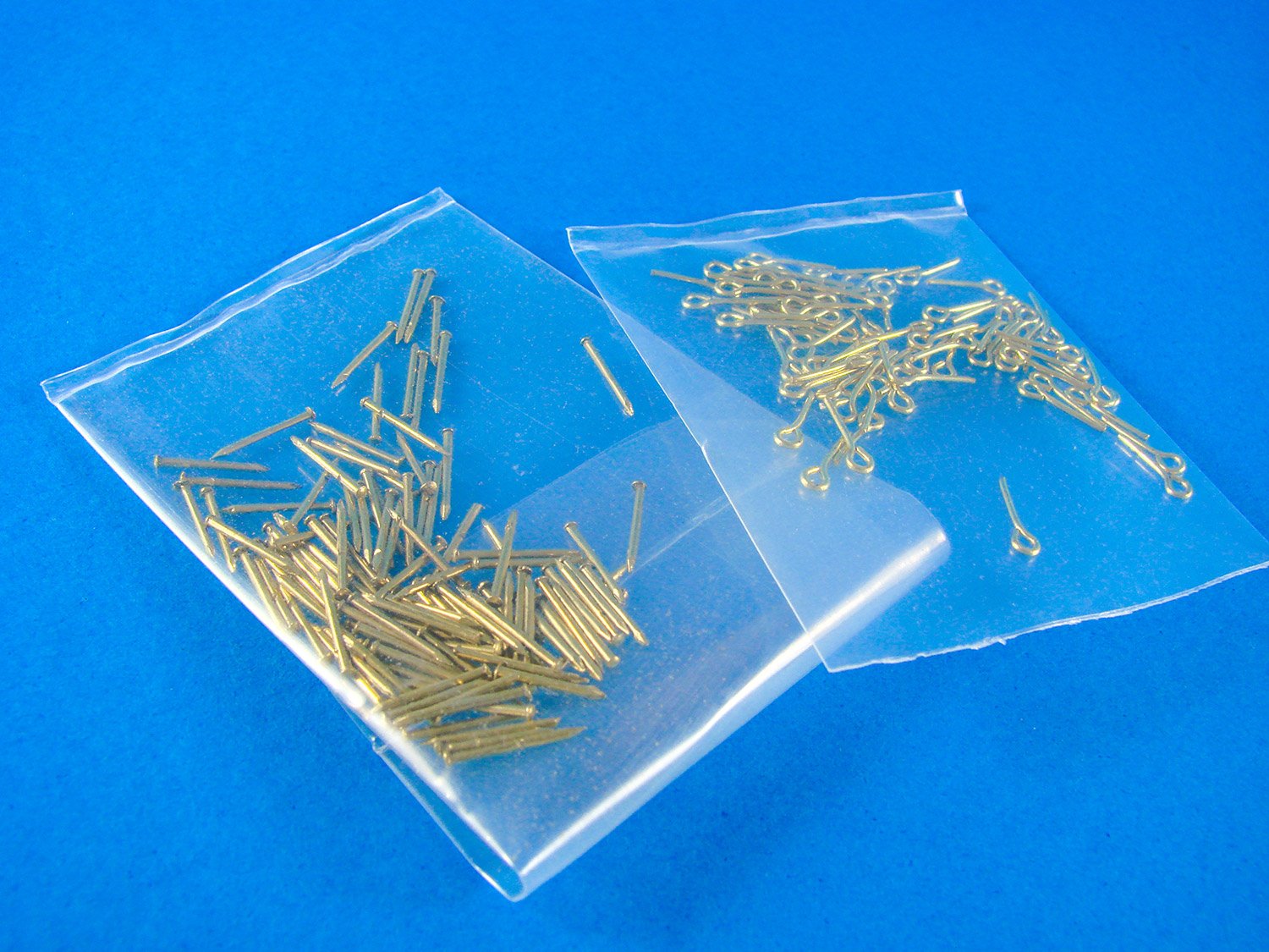
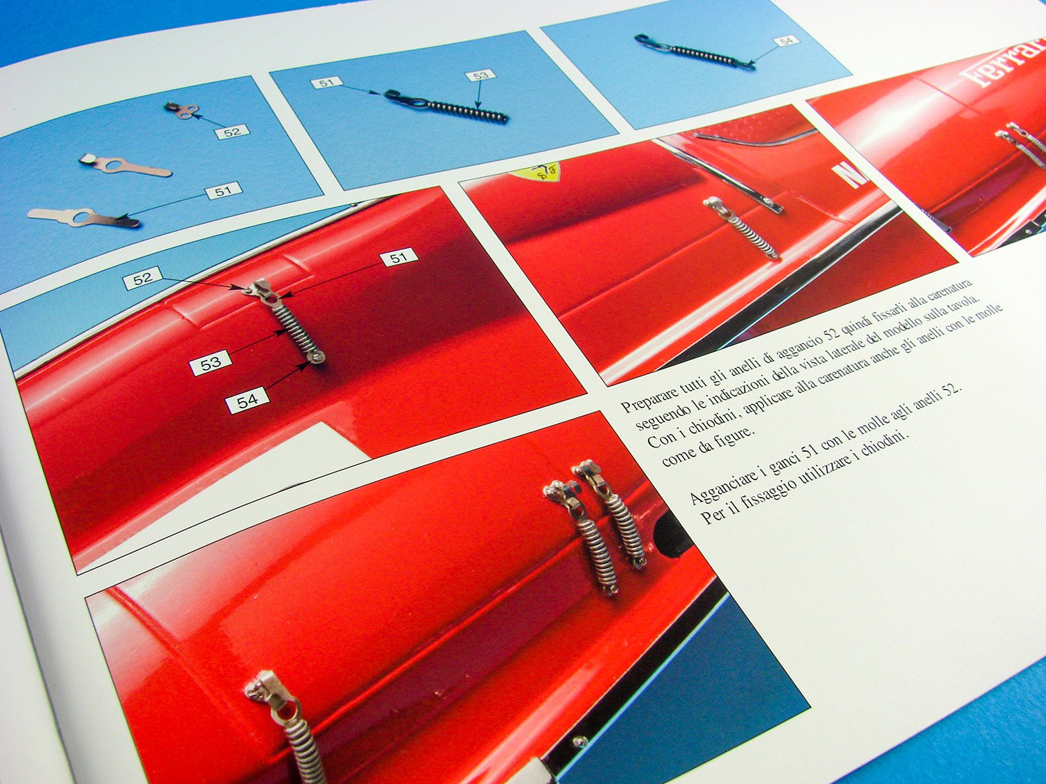
The mahogany hull will need to be drilled and fitted out with brass pins. These are scattered everywhere along the various planks on all sides of the timber unit. Whilst this is immensely tedious, the finish that it will provide will look amazingly authentic. If you want an RC model, I suggest you can the pins short, so they don’t protrude too far within the hull. When inserted, you really need to give the hull a delicate, overall sanding to ensure nothing stands proud of the surface. You can also see the cowl latch tensioning springs here and some fastenings for the model mounting brackets.
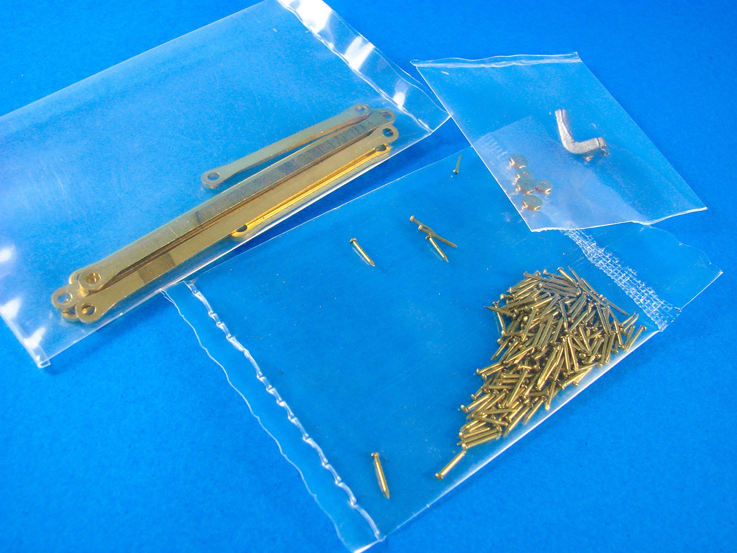
This packet contains printed instruments, a roll of rigging cord for which its inclusion still eludes me (!!) and also a few more brass parts that I still need to identify.

In another packet we have some dowel for constructing the foot pedal tube, and other material which would be used for syphon tubes etc.

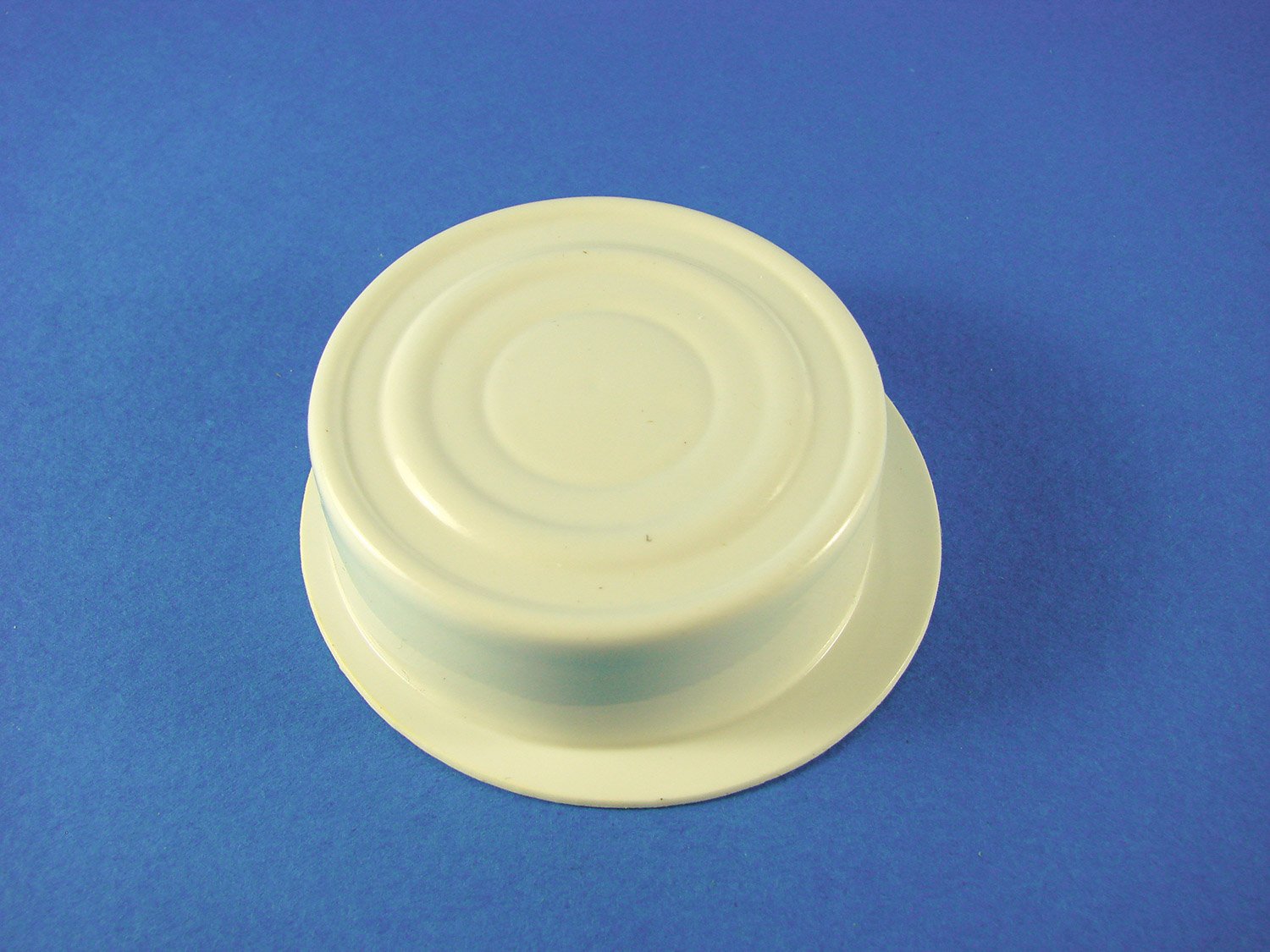
I think this part represents the rear of the fuel tank, possibly. It protrudes into the cockpit and is located behind the pilot’s seat. This is a vac-form part that needs trimming and painting in aluminium before installation.
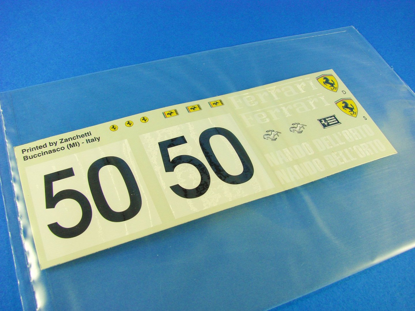
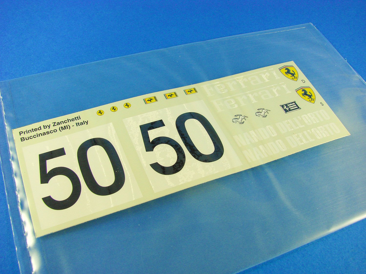
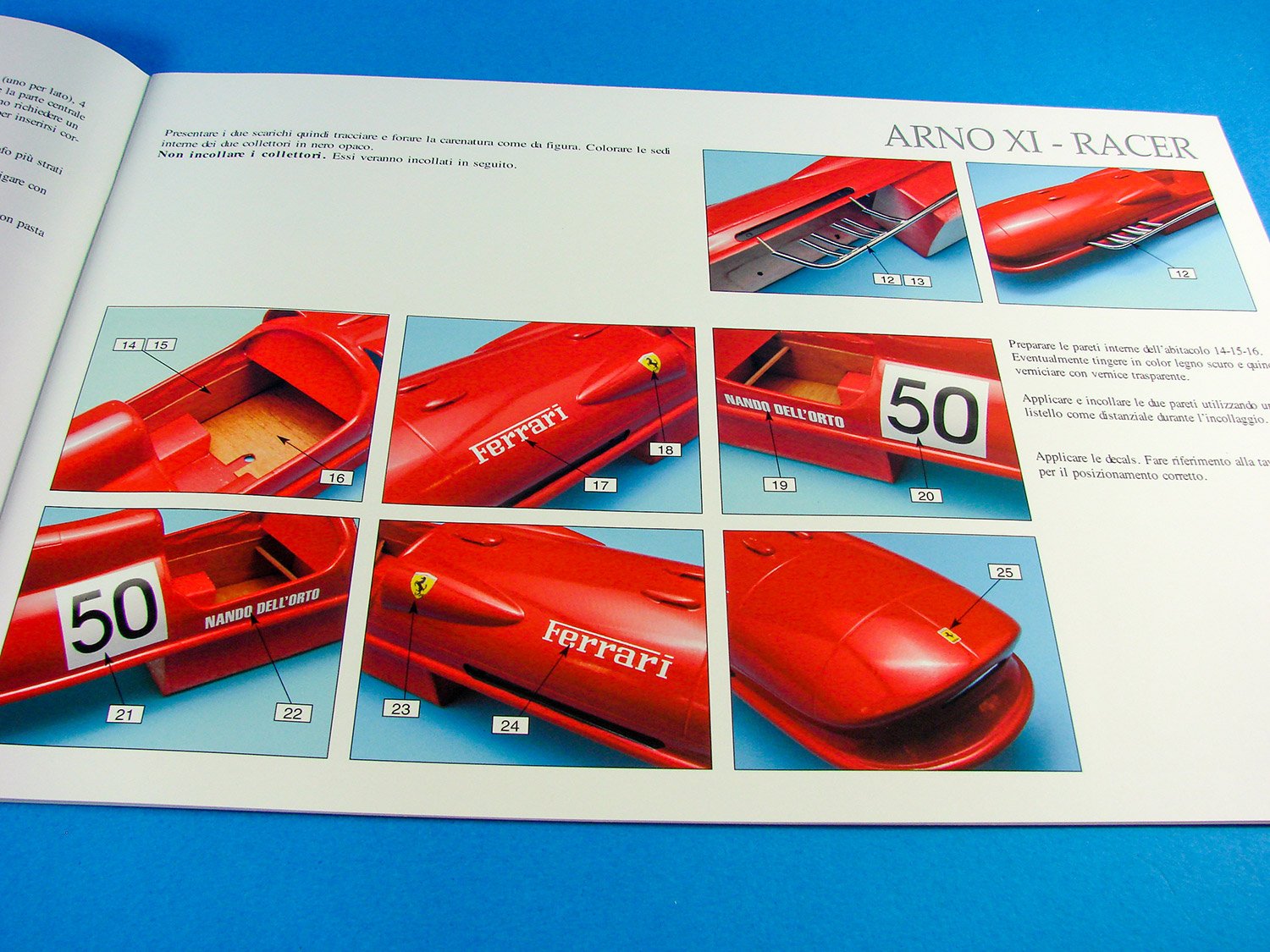
A sheet of decals is included for the superstructure exterior, with the race number, pilot name and also the iconic Ferrari logo and badges.
Again, not too sure about some stuff here, but I’m sure the acetate is included for the instruments.
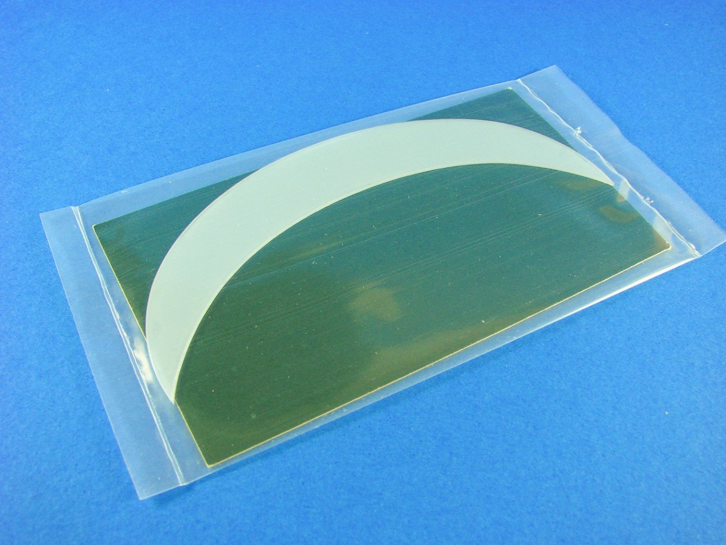
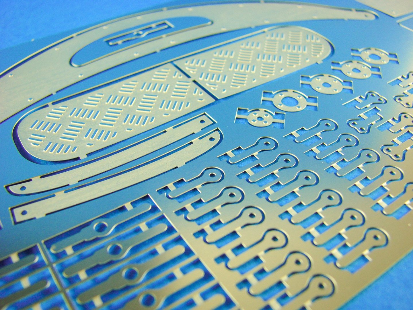
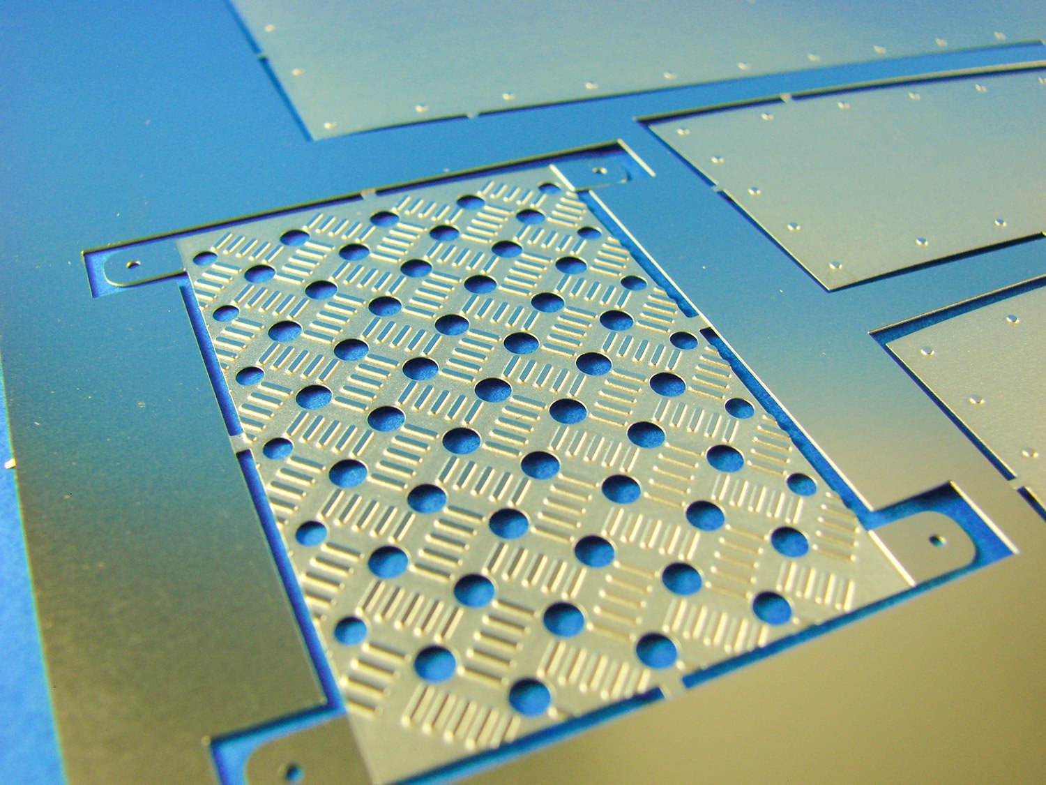
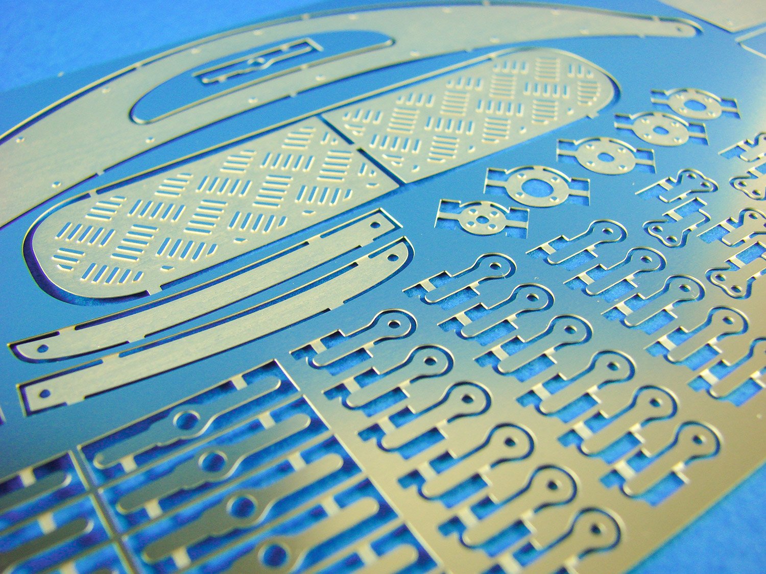
This LARGE photo-etch sheet is finished in nickel-silver and contains parts for the sides/undersides of the hydroplane wings, as well as for the cockpit floor.
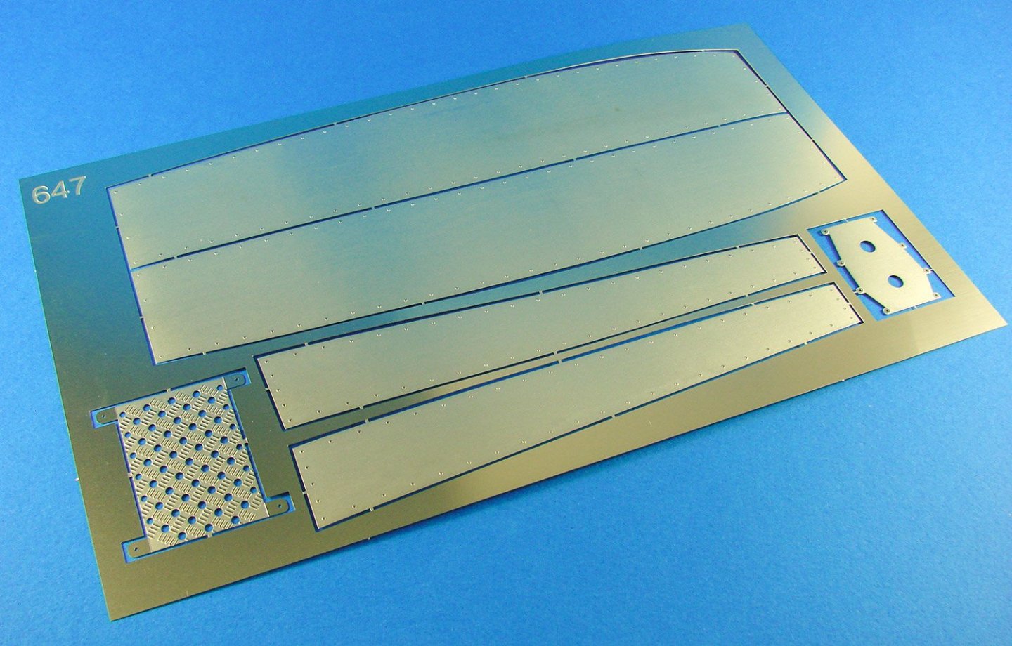
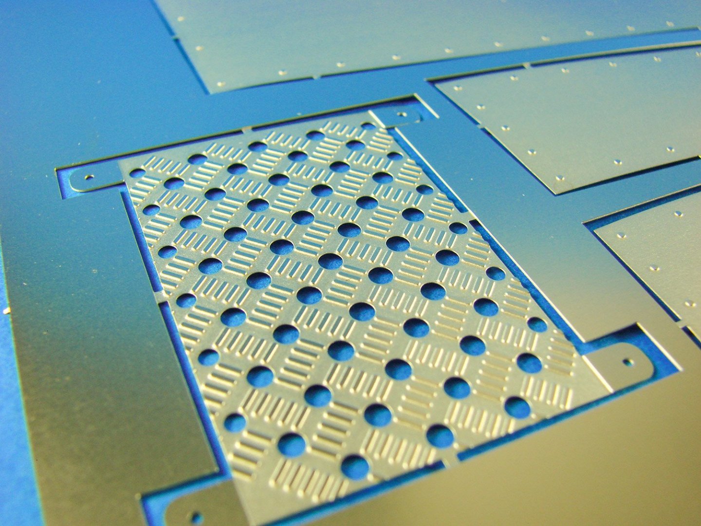
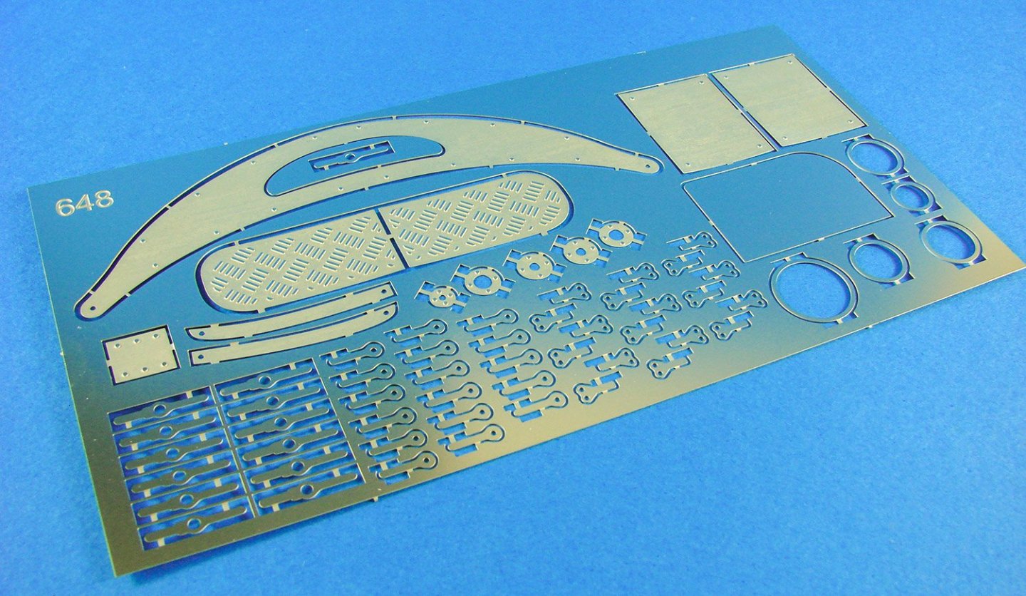
Another, smaller PE sheet contains finishing plates, latches, foot pedal plates, instrument bezels etc.
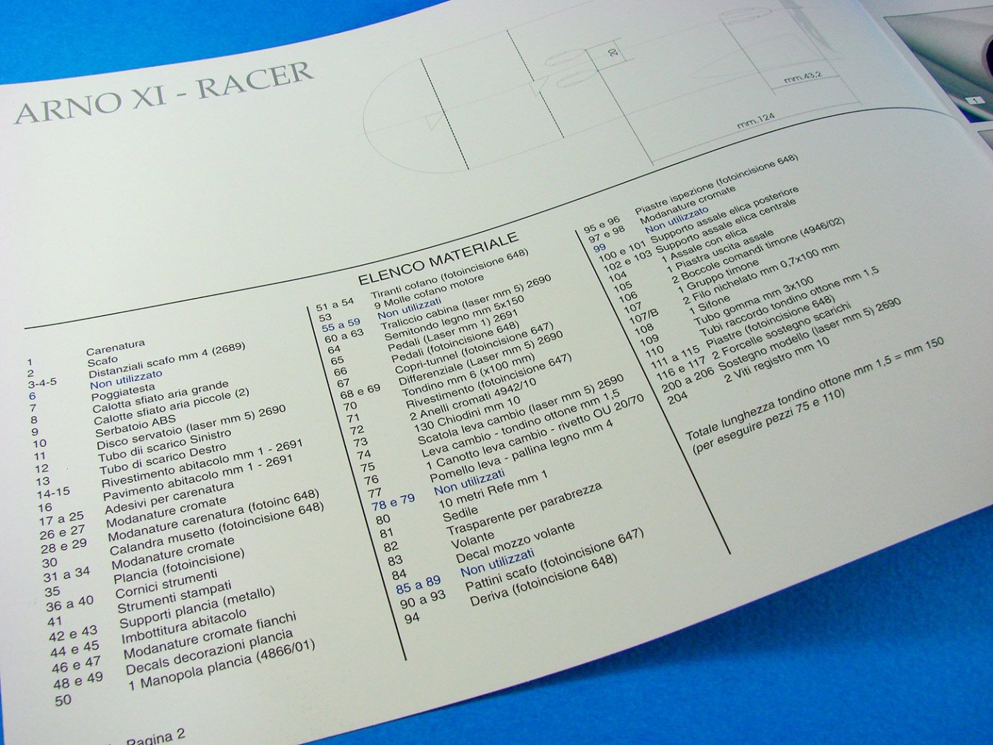
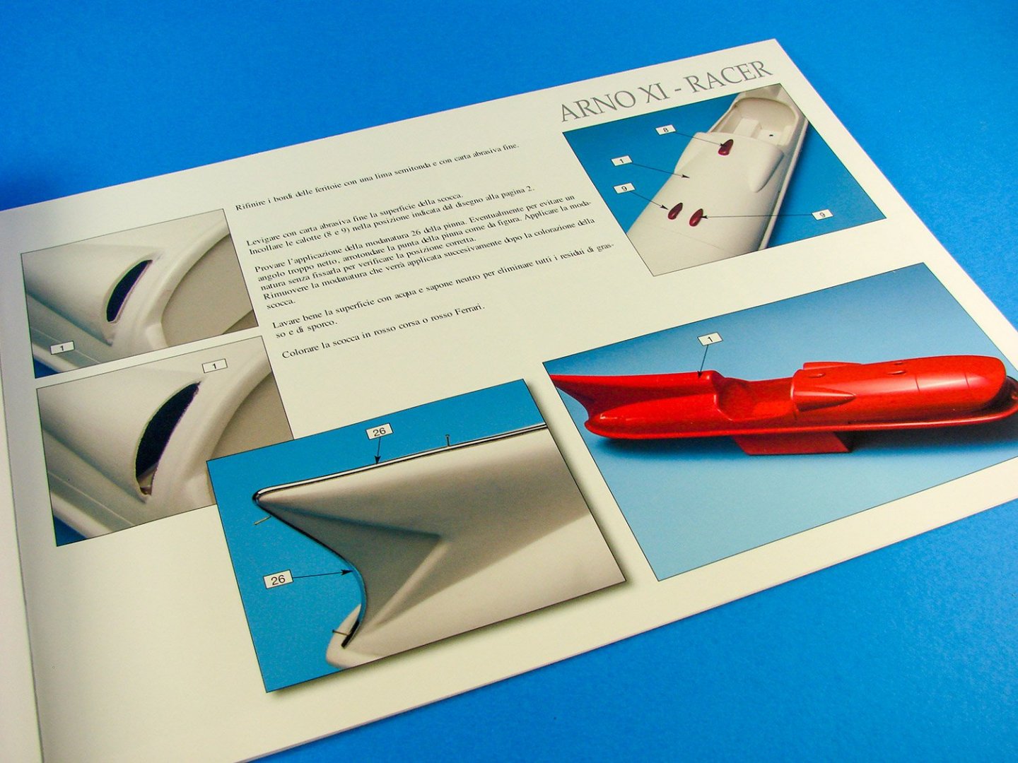
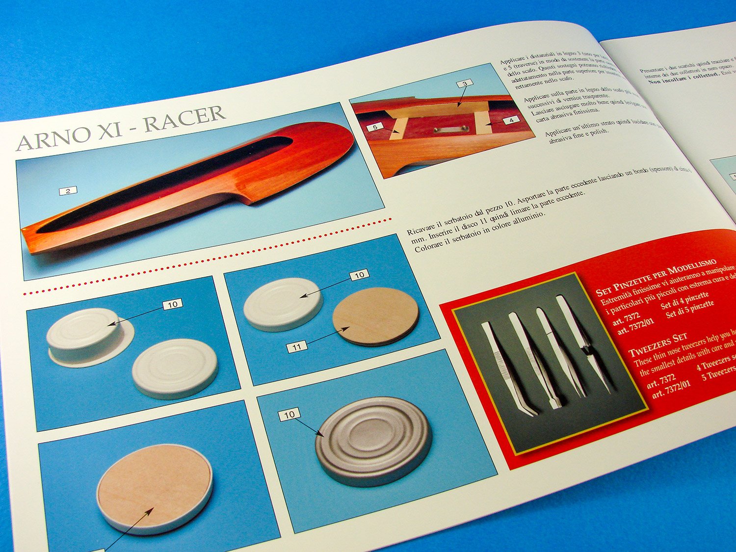
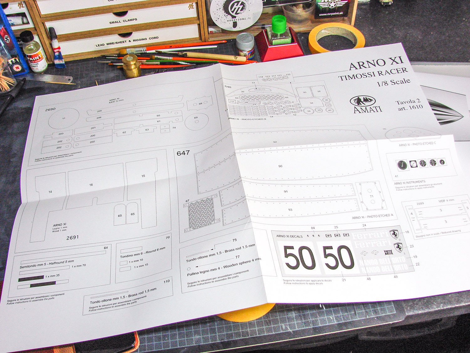
The instruction book for this kit is superb, being printed in colour photograph format, and with clear annotation. The only problem for uncultured types like me is that it’s in Italian. Things are pretty self-explanatory, but should you need a translation, then it isn’t too difficult with stuff like Google Translate etc. There are twenty pages in this manual, and I’ve photographed numerous here for you to get a feeling about the manual and the kit itself.


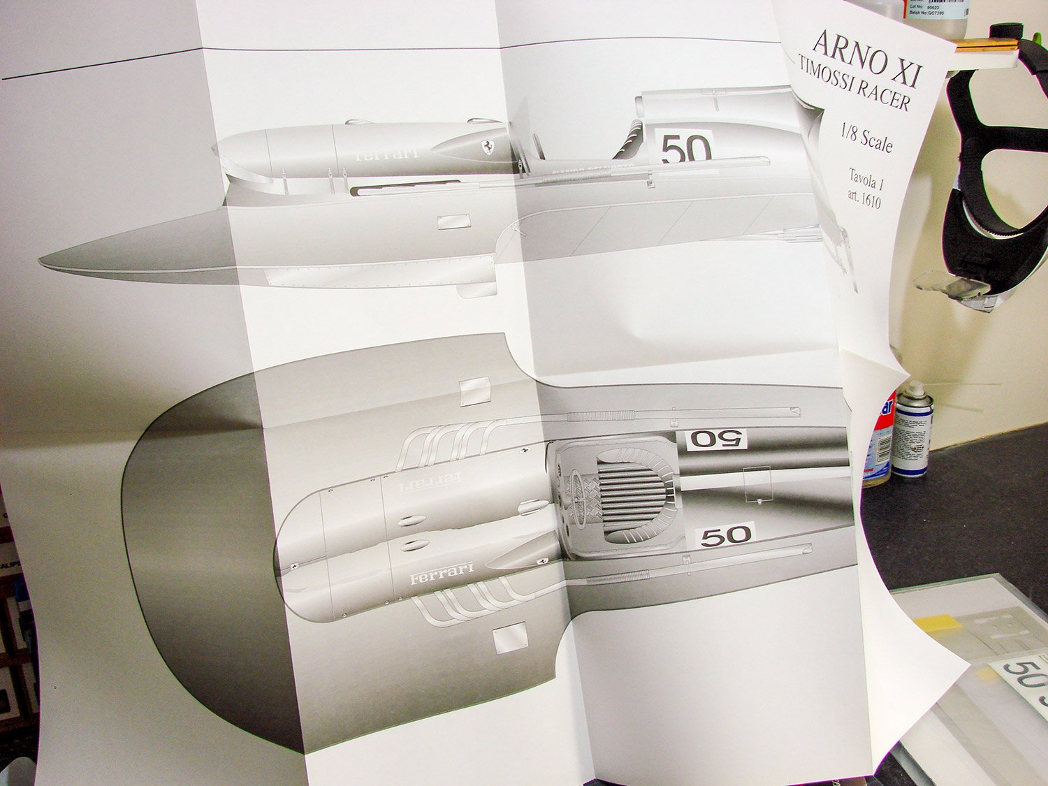
Two large plan sheets are included, one with several views of the actual vessel, and one with images of parts sheets etc.

Conclusion
This is quite an extraordinary kit, not just in subject choice, but also in the quality of the prefabricated parts. This is very much designed for someone who wants to either sail under RC or display in their cabinet/office, without too much of the fuss of spending countless hours in building, planking, sealing and polishing. The whole package is quite sumptuous, including the numerous fittings, photo-etch and of course that hand-stitched upholstery on the pilot’s seat. I do also think that the price of this kit, for what is offered, is very good value indeed, and yet still presents the modeller with a reasonable amount of work to do to create that famous Italian hydroplane. Amati’s instruction manual, albeit in Italian, is still straightforward to follow with its clear photographs and annotation. If this subject has ever tickled your fancy, get some Christmas money spent on one and create a truly iconic vintage vessel.My sincere thanks to Amati for the kit reviewed here on Model Ship World. To purchase, click the link at the top of this article, or contact your local Amati importer/distributor.

- Ryland Craze, DocRob, mugje and 11 others
-
14
-
25 minutes ago, greenstone said:
SO!
The first box of our new woodenkit is ready!
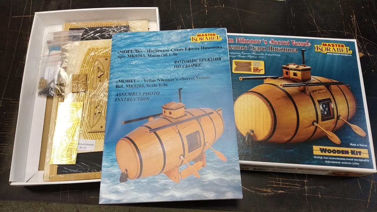
That was quick!
Season's Greetings to you and your team at Master Korabel!
- greenstone, Canute, ccoyle and 2 others
-
5
-
-
-
1 hour ago, Redshirt said:
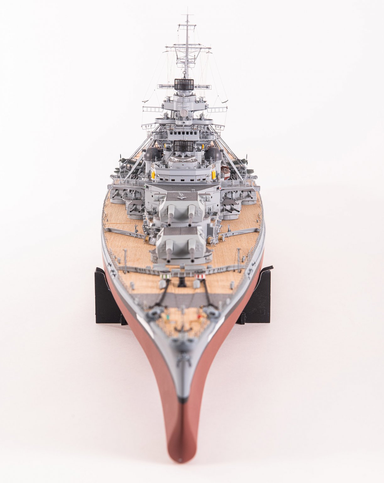
I understand the rationale for choosing Bismarck but tbh, it is a rather common and not terribly exciting subject.
I suppose that depends on whether Bismarck excites you 🤣
If it doesn't, then you'll bee ambivalent, but I know quite a few who are seriously looking forward to it.
- chris watton, catopower, Canute and 2 others
-
5


HMS Winchelsea - FINISHED - 1764 - by Chuck (1/4" scale)
in Member Build logs for the HMS Winchelsea
Posted
I have no words for this apart from that I'm stunned. 😲