BANYAN
-
Posts
5,852 -
Joined
-
Last visited
Content Type
Profiles
Forums
Gallery
Events
Everything posted by BANYAN
-
 Thanks Michael, I am assuming you used the coloured leads for the Nav Lights rather than paint? Seems to have done a very nice job. That assortment of leads will last you a lifetime; the coloured ones could indeed be very useful for markups. I like the liftouts etc for the drawers also; given me a couple of ideas there cheers Pat
- 749 replies
-
- 2
-

-
- albertic
- ocean liner
- (and 2 more)
-
The hull is looking fantastic Steven; a testament to your search for accuracy and quality. cheers Pat
-
Great progress Michael, the end is indeed in sight Can I ask what that 'pencil' is in the pen that you show in the photo of the nav lights? Is it some sort of crayon or paint pen? May be the exact sort of thing I am looking for (as a suggested solution) to painting on the brass plates on the ship's wheel. cheers Pat
- 749 replies
-
- 4
-
-
- albertic
- ocean liner
- (and 2 more)
-
Great progress Patrick, Omega looks fantastic. Excellent level of detail for the sale you are working at - impressive! cheers Pat
-
Hang in there Carl; you know the saying "when the going gets...." I am sure you will get through them with the appropriate doses of 'rum' and 'lash' cheers Pat
-
Look forward to the updates OC; great to hear the hand is not troubling you so much. cheers Pat
-
Those cranes look great Greg; even if you don't think they are that good. Great to see you didn't let them beat you - must be colleagues of IKEA instruction authors cheers Pat
- 405 replies
-
- 9
-
-
- tamiya
- king george v
- (and 2 more)
-
Good to see you persisting Denis - great progress. Stay with it mate; just walk away from it for a while if needs be - getting the head right (not just for the hobby) is more important! cheers Pat
- 1,090 replies
-
- 8
-
-
- showcase models
- vendetta
- (and 2 more)
-
Extreme Clipper Witch of the Wave CAD
BANYAN replied to rtwpsom2's topic in CAD and 3D Modelling/Drafting Plans with Software
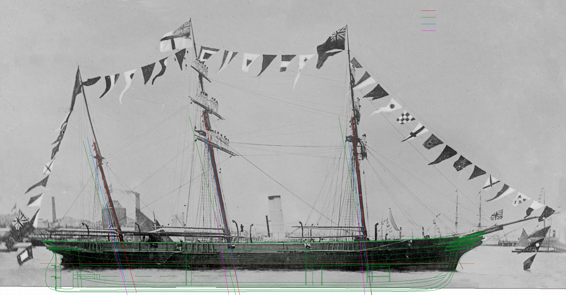
With regards to mast rake angles, in some latter clippers, and with Victoria, the rake angles were indeed 'extreme'. I have a discussion in my log, but from the only surviving drawing by the ship's designer (Oliver Lang) the rake of Victoria's masts were from fore to aft - 5 deg, 10 deg and 15 deg. This caused some disbelief at first so I overlaid the rakes measured from a profile photo, two lithographs and the plan and it was indeed as extreme as the plans suggested. The differences in positions can be accounted for by the various 'aspects' the ship was depicted - the photo is slightly stbd bows on, one of the lithos slightly port bows, the plan true profile etc. cheers Pat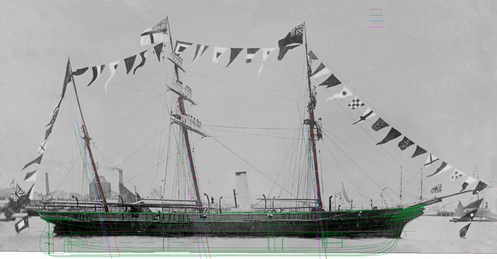
-
Thanks again for sharing Bob; I am a convert to Japanese (pull) saws also - except for my larger saws, all are now pull-saws. I find them easier to use and for some reason (opinion) appear to provide a cleaner finish. I also prefer Japanese knives (marking etc). I like the idea of changing the handles on the saws also; hadn't thought of that - watch out I may copy your workshop cheers Pat
-
Extreme Clipper Witch of the Wave CAD
BANYAN replied to rtwpsom2's topic in CAD and 3D Modelling/Drafting Plans with Software
Thanks - one day I hope to produce a 3D hull shape for Victoria but I am still getting to grips with her construction which used diagonal planking rather than the standard for/aft strakes on frames. Above the 'round' she did not use traditional frames but rather iron plates (Lang's Plates) I am assuming. These supported three layers of planking separated by sheets of impregnated felt with the two inner running at 30 degrees to each other, and the outer skin (planks) running fore/aft. This method of construction was used as it provided greater hull stiffness/strength to cater for the steam power/propeller - more expensive at the outset but cheaper through the life span of the ship. On her breakup some 30+ years later, the yard reported her hull was as sound as the day she was built. She did have a similar sailing rig to clippers with many clipper ship rigging elements included that the RN did not incorporate until much later, and some not at all - all these improvements were in the interests of minium manning. Anyways enough prattling on about Victoria; I will keep that for my log. I will follow your techniques closely to see how you do this. i have TurboCAD with 3D capability but I am not sure I will use that yet. cheers Pat -
Many thanks for the photos and video Bob; perfectly clear . Now to to modify mine. I liked the idea of holding the 'modified' bench hook also, better working height for smaller cuts. cheers Pat
-
Hi UV, glad to hear you are ontop of the personal issues and will be back with your great build again soon; look forward to your next update (when ever it is - life comes first) cheers Pat
- 786 replies
-
- 1
-
-
- Royal Louis
- Finished
- (and 1 more)
-
Extreme Clipper Witch of the Wave CAD
BANYAN replied to rtwpsom2's topic in CAD and 3D Modelling/Drafting Plans with Software
A very interesting ship and great summary of your process; I will be interested in following this log. I'll have a closer look later today but from my limited experience in drafting these sorts of plans (2D only), all looks pretty good. there are a few guys on here with much more extensive knowledge and experience in this whom I am sure will be only too happy to help out in answering queries. I am currently researching, and trying to draw (2D) a set of plans for the HMCSS Victoria (1855) which was fitted out as a yacht internally, but retained a Gun Despatch Vessel armament and equipment, many of which were very advanced fittings for that era - purchased by, built for the colony of Victoria, but built in Limeyard Docks, London. I am sure I will learn a few useful tips along the way; and if there is anything I can contribute will be more than happy to share cheers Pat -
HMCSS Victoria 1855 by BANYAN - 1:72
BANYAN replied to BANYAN's topic in - Build logs for subjects built 1851 - 1900
Thanks for looking in and the suggestion Marty; much appreciated. Unfortunately, when I asked about vinyl masks or vinyl decals the first question was - how small??? the dots are about .5mm and the plates .8 x .6 so much too small unfortunately. I might reinvestigate that though as I was able to print decals. cheers Pat- 993 replies
-
- 4
-
-
- gun dispatch vessel
- victoria
- (and 2 more)
-
That looks really good Michael; not much left now. More room in the workshop - any ideas of what is next? cheers Pat
- 749 replies
-
- 3
-
-
- albertic
- ocean liner
- (and 2 more)
-
ancre Chebece 1750 by Jeronimo - FINISHED
BANYAN replied to Jeronimo's topic in - Build logs for subjects built 1501 - 1750
I very much enjoy following your build log Karl; exceptional workmanship and a joy to behold. cheers Pat -
Stunning work Dave; even at extreme close-up your work is clean and crisp. The rigging is looking very good. cheers Pat
-
HMCSS Victoria 1855 by BANYAN - 1:72
BANYAN replied to BANYAN's topic in - Build logs for subjects built 1851 - 1900
Thanks again for all those that have looked in and 'liked' my latest posts - much appreciated. You're right with that aspect of modelling Eberhard. As frustrating as researching is at times, there is much satisfaction when you resolve such issues. Very many thanks for your kind comments Michael; noting your own work these comments are much valued. Thanks Denis; appreciate your suggestions and the problem you describe is exactly the issue I am experiencing. I have found some good "waterslide" superthin decal paper which is laser printer compatible so I can use TurboCAD to draw up the decals and print them. Is that what you mean by 'decal program'? cheers Pat- 993 replies
-
- 3
-
-
- gun dispatch vessel
- victoria
- (and 2 more)
-
Not sure if you have resolved this Michael; but from my 'limited' knowledge this appears to be a HF radio antenna. Some form of 'fan aerial' with four risers (fore/aft and port/stbd) rising to a point at the insulators on the wire stay above (which may be a 'long wire HF aerial'. There are also four legs (horizontal) that form a crucifix shape and connect to the four risers - these were used to form the 'ground plane' for the aerial. One leg of this would have had to have been 'earthed' but cannot make out enough detail to see if the 'loop' bit was the earth or not. The natural cordage may have been used to raise/lower the top of the aerial to the wire stay/wire aerial? This was natural fibre probably to minimise static and prevent 'interference' with the main aerial. Not sure I can make it out but is this in the form of a simple whip tackle? A heavier duty tackle would not have been required I think. cheers Pat
- 749 replies
-
- 7
-
-
- albertic
- ocean liner
- (and 2 more)
-
You have certainly mastered the manipulation of PE Greg; looks great! That shot of the dry fit sure shows how much detail was on these beasts. A wonder you don't get RSI from all that PE folding. cheers Pat
- 405 replies
-
- 7
-
-
- tamiya
- king george v
- (and 2 more)
-
HMCSS Victoria 1855 by BANYAN - 1:72
BANYAN replied to BANYAN's topic in - Build logs for subjects built 1851 - 1900
Thanks for all the likes, and for the encouraging comments Marty and Eberhard. That's a great idea Eberhard, I'll have a poke around online to see if I can find one of those pens - my shaky hands are the real problem as 'discipline' will really be the operative word here :). When I looked at the photo the 'scale ratios' of the companion to the wheel assembly looked wrong. The wheel size is correct but it appeared too low. A prolonged discussion with an engineering friend isolated the issue. I had been working on the assumption that the rapson slide tiller arrangement was fitted to the underside of the weather deck. However, a closer examination of the patent drawings shows it was actually above deck and the rudder head penetrated above deck also. We are now reasonably sure the wheel assembly would have sat on top of a closed in 'box' arrangement that contained the rapson slide and pulleys etc; which would then raise the wheel assembly to the height suggested in the photo posted earlier. This arrangement would then allow the control rods for the propeller (clutch, pitch and locking) to rise to the upper deck also (confirmed by actual drawing of the propeller fit) whereas I had been frustrated with how to 'swing' the tiller arm without impacting these rods. Furthermore, it now allows the fitting of 'Lang's' emergency tiller arm abaft the rudder head without impact on its length as had been the issue by trying to fit into the space/ void below deck - a double win all round A drawing will follow. Surprising how eventually these issues resolve with a persistent pursuit aided by visual prototyping. cheers Pat- 993 replies
-
- 6
-
-
- gun dispatch vessel
- victoria
- (and 2 more)