Chuck Posted August 17, 2022 Author Share #1651 Posted August 17, 2022 Ihave no idea...but let us know how your experiments work out. FrankWouts 1 Chuck Passaro - MSW Admin Sloop Speedwell - POF scratch Block Island Boat - POF scratch HMS Winchelsea - POB scratch build HM Cutter Cheerful - POB scratch build Royal Barge - POF scratch Medway Longboat- POF Scratch SYREN SHIP MODEL COMPANY Link to comment Share on other sites More sharing options...
gulfmedic1 Posted August 25, 2022 Share #1652 Posted August 25, 2022 On 2/9/2018 at 1:51 PM, Chuck said: FYI...The reason for the alternative woods is two-fold. First to make these projects affordable and Boxwood and pear are very expensive. In addition, I am not sure you guys are aware of this yet, but you will be soon. The price for C.Boxwood has increased 75-100% over the last two-three months. There are very few places in the US right now where you can get really nice stuff without grain that is creamy and wonderful. At least not in the large sizes that I need. The current costs for this stuff is now $40 and up per BF. I was getting it for almost half that price six months ago. Just got what is probably my last shipment of awesome looking boxwood this morning at that price before I have to either raise my prices or start thinking about a different wood overall. When your wood guys run out of their pile....they will be very shocked to learn about the increase. And will probably pass that on to you. So my advice....if you use boxwood a lot, buy all you can over the next few months from where ever you can find it. You are looking at really nice boxwood boards that are 3+" thick, 5-5 1/2" wide and 30" long. If you knew how much this stack of wood cost you wouldnt believe it. I am looking to buy another batch within the next few weeks to try and hoard it at the lower prices where ever I can find it. Gilmer now charges the lowest at $40 per BF. Other sources have garbage boxwood or its even more money with boards half the thickness and width. This is also the reason guys why my block inventory has been in bad shape. I was waiting on this nice stack of wood. Once I find time to mill it up I will get right on restocking the sizes of blocks I am out of. Chuck Chuck I know what you mean. I do other wood working and the wood I used has gone up so much I cant afford it even now in 2022, and here in Southern US every time we have a hurricane it shoots up even more FrankWouts 1 Phantom solid hull first build Link to comment Share on other sites More sharing options...
Chuck Posted August 25, 2022 Author Share #1653 Posted August 25, 2022 Its getting crazy now…yellow cedar used to cost me $10 per bf. As of this week after placing an order it has shot up to $19 per bf. This is for the primo stuff which we need. You can buy garbage Cedar wood cheaper but would have to throw half of it in the fireplace. boxwood and pear is way up there in the USA. Its actually cheaper for me to order a few hundred pounds of pear from Europe and have it shipped to me than buy it in the states. Its nuts. I havent raised my prices for my products yet over the last six years but sadly after the wood prices almost doubled now…I may have to. Chuck Edwardkenway, druxey, Ryland Craze and 1 other 2 1 1 Chuck Passaro - MSW Admin Sloop Speedwell - POF scratch Block Island Boat - POF scratch HMS Winchelsea - POB scratch build HM Cutter Cheerful - POB scratch build Royal Barge - POF scratch Medway Longboat- POF Scratch SYREN SHIP MODEL COMPANY Link to comment Share on other sites More sharing options...
gulfmedic1 Posted August 25, 2022 Share #1654 Posted August 25, 2022 Ive lucked out my father in Law has a lot of mixed prime wood above his garage that I can get from him. One of my sons parents had some red cedar trees knocked down and they let me go cut it and get it and I had it milled. My cost about 150 and ended up with 85 planks of beautiful cedar. We have a lot of tree cutting companies here in Louisiana some times Ill go to them before they cut the wood for fire wood and by a piece of a big branch or trunk. Typically Im looking for pecan or oak. FrankWouts 1 Phantom solid hull first build Link to comment Share on other sites More sharing options...
gulfmedic1 Posted August 25, 2022 Share #1655 Posted August 25, 2022 On 7/6/2019 at 8:01 AM, Chuck said: I also just got a wonderful batch of raw cherry lumber. I thought I would show you guys. The Winnie will also be available in cherry. From this very cherry board. Its really nice stuff and some of the best I have bought. Very clear cherry with little to no gum pockets and sap spots. Once I get some of this milled along with a few more boards of cedar I will actually start laser cutting parts for the first two Winnie parts. This way I have a bunch in stock when I am ready to launch. Chuck so on this board you will cut the plank strips from where I circled and put number 1? FrankWouts 1 Phantom solid hull first build Link to comment Share on other sites More sharing options...
Chuck Posted August 25, 2022 Author Share #1656 Posted August 25, 2022 I am really not sure what you are asking. It depends on what I am using it for. For planking sheets used to rip planking strips ....yes I will cut cherry or AYCedar that way. But other types of wood may be different. But on Cherry and AYC that is the best way to get grain free clear strips for planking.... FrankWouts 1 Chuck Passaro - MSW Admin Sloop Speedwell - POF scratch Block Island Boat - POF scratch HMS Winchelsea - POB scratch build HM Cutter Cheerful - POB scratch build Royal Barge - POF scratch Medway Longboat- POF Scratch SYREN SHIP MODEL COMPANY Link to comment Share on other sites More sharing options...
gulfmedic1 Posted August 25, 2022 Share #1657 Posted August 25, 2022 Thank you sir that is what I was asking FrankWouts 1 Phantom solid hull first build Link to comment Share on other sites More sharing options...
Jim Rogers Posted August 30, 2022 Share #1658 Posted August 30, 2022 Chuck is the ship’s boat going to be mounted to beams across the mid ships gun deck? Are these beams shown on sheet 4 of the plans? Regards, Jim Rogers Damn the Torpedoes , Full speed ahead. Adm David Farragut. Link to comment Share on other sites More sharing options...
Chuck Posted August 30, 2022 Author Share #1659 Posted August 30, 2022 Actually you have a choice. You can use skid beams or you can use two spare topmasts. Its up to you. I am gonna use two spare topmasts. Rustyj, KentM and scrubbyj427 3 Chuck Passaro - MSW Admin Sloop Speedwell - POF scratch Block Island Boat - POF scratch HMS Winchelsea - POB scratch build HM Cutter Cheerful - POB scratch build Royal Barge - POF scratch Medway Longboat- POF Scratch SYREN SHIP MODEL COMPANY Link to comment Share on other sites More sharing options...
Blue Ensign Posted August 30, 2022 Share #1660 Posted August 30, 2022 According to Brian Lavery (Arming and Fitting) skid beams were standard by 1750, initially with iron crutches to secure them, but he indicates that their use on Ships of the line became more permanent by the 1780's. His comments regarding frigates which is more relevant to Winchelsea is that; Frigates were rather slower in adopting gangways and boat booms and do not appear to have them until the early 1800s. I think Chuck's approach of spare topmasts to support a ships boat feels more appropriate, and more aesthetically pleasing in relation to 'Winnie' of 1764. B.E. scrubbyj427, Rustyj and KentM 3 Current Build: HMS Indefatigable-1794-by-blue-ensign-vanguard-models-164-scale Medway-longboat-1742-by-blue-ensign-½”-scale Completed builds: HMS Sphinx 1775 by Blue Ensign. 1:64 scale - Vanguard Models Queen-Anne-Royal-Barge-circa-1700-by-Blue-Ensign Fifie fishing boat Lady Eleanor Muirneag-1903-–-a-scottish-zulu-fishing-boat-164-scale-based-on-the-vanguard-models-zulu-kit/ HM Cutter Alert 1777 HM Cutter Cheerful 1806 18th-century-English-longboat-by-Blue-Ensign-ms-148-scale/ finished 18thc English Pinnace by Blue Ensign-Model-Shipways-1:24 scale/ finished HMS-Pegasus-by-Blue-Ensign-finished-Victory-Models-1:64-scale/ Heller Seventy-four 1:150 scale - modified Le Superbe/Le Glorieux kit after Boudriot, waterline setting with sails. The schooner Pickle, Jotika pob kit 1:64 scale, my interpretation. Link to comment Share on other sites More sharing options...
Chuck Posted August 30, 2022 Author Share #1661 Posted August 30, 2022 this is how I will probably show the barge. I agree that skid beams were in use but it was hit or miss. It also doesnt look as pretty. In addition only one boat like this one is the best approach for me. More than this and the boats just take up all the interest and become the focal point. Something I would like to avoid. The contemporary model pictures is from the era. A real good match to what we are doing with Winnie. scrubbyj427, Jim Rogers, glbarlow and 12 others 15 Chuck Passaro - MSW Admin Sloop Speedwell - POF scratch Block Island Boat - POF scratch HMS Winchelsea - POB scratch build HM Cutter Cheerful - POB scratch build Royal Barge - POF scratch Medway Longboat- POF Scratch SYREN SHIP MODEL COMPANY Link to comment Share on other sites More sharing options...
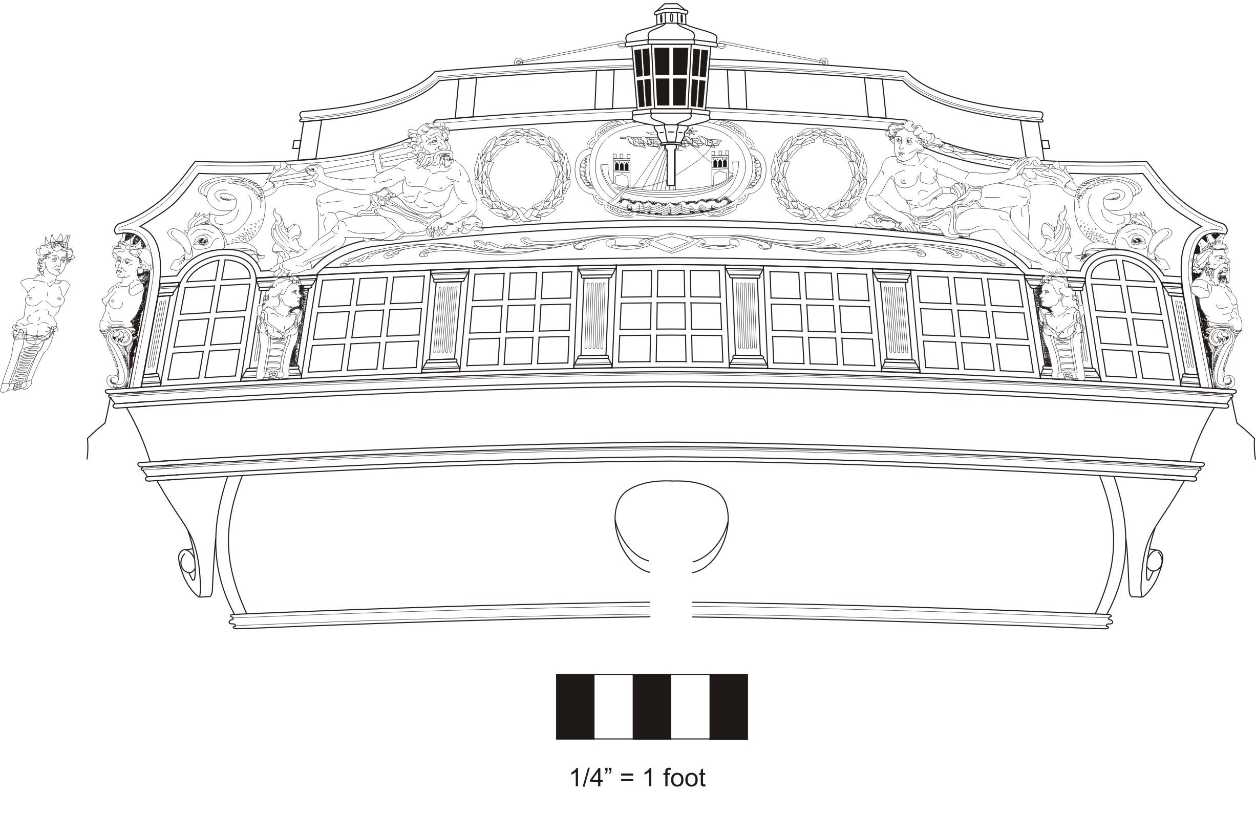
Chuck Posted September 5, 2022 Author Share #1662 Posted September 5, 2022 here is the step by step for making the cathead supports. These pieces are among the most difficult to make for any ship model. This method may seem a bit unorthodox....but bear with me here and I will explain as best I can. Ask a lot of questions!!! The laser cut parts will get you only so far...about 80% of the way. You will need to shape these and tweak them to get a really good fit. But its leaps and bounds better than anything you will find on a kit as long as you take your time and dont rush through it. Read the instructions several times. Step one...A laser cut template from 1/32" thick wood is provided. Temporarily glue this in position with just a few drops of glue or rubber cement. Mark the side where you will have to remove the molding so your support will fit between them. Cut the molding free with some sharp chisels. NOTE....cut inside your lines and make the gaps smaller...dont make them too large. You can always make them larger later as you test fit each piece. The template is longer than you will need on both ends so you can cut it to fit your model so it fits. Look at it from many angles to see if the curve is graceful and it runs well into the middle rail where it connects. There should be a pleasing continuity from the template onto the middle rail. Step 2...assemble the cathead support....NOTE, the entire span will be made of two lengths. This portion of the support is just half and is directly under the cathead. There are several layers...the bottom is the longest. It is 1/4" thick cedar. On top of this glue two more shorter layers of 1/4" thick cedar. Then to finish the assembly...glue on the a final piece which is 5/32" thick boxwood. It is super important to make sure you use the boxwood layer as the top layer. This layer will show and its the tip or outboard end of the cathead support. Four layers in total. I said it was gonna get weird. But just stick with me here. There are templates in paper for this piece. See them in the photo. Step 3....Glue the template onto the piece so it all fits nicely. There is plenty of room. I glued it on the outside only. Use this as a guide to shape this piece. Remove the heavy stuff with a sharp blade until you get close to the template and sand the rest. This will get you 80% of the way to a good fit. After shaping....below. Dont over sand. Just smooth out the sides. Dont try and remove all the char as it doesnt matter. You just want to have a smooth surface to add the outside layers in the next step. Step 4....There are laser cut outside layers that are super thin. These come in two pieces. They are glued on both sides. Do this neatly and get a nice clean joint between the two sections. You may want to lightly sand the char from where the joint will be between these two pieces so it wont show when its all done. It will look like this. A few things to note... Before gluing them on each side I rounded the edges of the support or chamfered them. Then add the thin outer layers. Sand them flush on all edges although NOT on the front fancy side where the friezes will go. Similar to the cheeks we made you want to leave the edges standing proud on the front side to form a slight lip. see below. I left it a little more pronounced until after the friezes are added and its all cleaned up. Also note the second length which will connect to it and the middle rail. This is laser cut for you and also gets thin outside layers. This is important because these two pieces will join together like the cheeks did with the hair brackets. You will need to get a nce joint between them which wont be seen when these are glued together. Step 5...this forward length is laser cut but needs shaping. It has one curve cut into it but you need to shape the other side. You need to sand the curve that fits against the hull. Just like the cheeks above and below the hawse holes. You have done this before. See below. Also note the angled forward end which needs to be sanded into it. This end is what attaches to the middle rail. I rounded off or chamfered the outside edges before adding the two thin layers. All of these parts are cut extra long so you can shape and tweak to fit you model. This is where is gets interesting.... You should have both halves at this point completed.....like this. At least roughly done so we can test and tweak them on the model. There are lots of angles here. Step 6A....This is just a dry fit of both lengths trying to get a tight seem between both lengths. First I added the cathead support...tI tweaked the top edge so it was at the proper angle to fit against the bottom of the cathead. You will no doubt have to do this. You will also have to tweak the shape that fits against the hull. Dont sand away too much. Do a little at a time and keep testing until it fits nicely and follows the path of your template. Then temporarily glue it in position with a drop or two of glue. Step 6B....Do the same tweaking of the forward half so it sits flush against the hull. But you also need to create a nice tight joint between the two halves so it looks seamless. The angled forward end should fit snug against the middle rail. Keep working both lengths until you get a pretty good fit....below. See how it fits between the molding on the hull? Step 7...now you can do some last minute tweaks and glue it all on the model. I added the friezes after the both lengths were glued on the model. I put the friezes on in two lengths. It was just easier this way. Then I sanded the edges of those outside layers a bit with 600 grit paper so the the beaded edge wasnt standing too proud of the friezes. Overall I just did some touch up work. I think I still need some more but this is about it as far as the method is concerned. There is NO easy way to create these. This is not a plastic kit model. But this technique can be adopted for scratch building. This is indeed how I make these parts when I do a scratch built model. I just translated it to laser cut parts. Having said this, because everyones models will be slightly different you will need to go slow and shape them for a best final fit. And as always....ask a lot of questions. Gregory, Gahm, Rustyj and 31 others 28 6 Chuck Passaro - MSW Admin Sloop Speedwell - POF scratch Block Island Boat - POF scratch HMS Winchelsea - POB scratch build HM Cutter Cheerful - POB scratch build Royal Barge - POF scratch Medway Longboat- POF Scratch SYREN SHIP MODEL COMPANY Link to comment Share on other sites More sharing options...
scrubbyj427 Posted September 5, 2022 Share #1663 Posted September 5, 2022 Brilliant! I love where this is going. 🍿 FrankWouts 1 Current Builds: HMS Winchelsea 1764 1:48 - 5th rate 32 gun frigate (on hold for now) HMS Portland 1770 Prototype 1:48 - 4th rate 50 gun ship Link to comment Share on other sites More sharing options...
Wacom Posted September 5, 2022 Share #1664 Posted September 5, 2022 Looking really good and as always shows the amount of time and thought that goes into this ship before any wood is cut. Will this chapter also be available in Cherry? FrankWouts 1 Reg Link to comment Share on other sites More sharing options...
Chuck Posted September 5, 2022 Author Share #1665 Posted September 5, 2022 Thank You....Yes there will be a cherry version as always. FrankWouts 1 Chuck Passaro - MSW Admin Sloop Speedwell - POF scratch Block Island Boat - POF scratch HMS Winchelsea - POB scratch build HM Cutter Cheerful - POB scratch build Royal Barge - POF scratch Medway Longboat- POF Scratch SYREN SHIP MODEL COMPANY Link to comment Share on other sites More sharing options...
glbarlow Posted September 5, 2022 Share #1666 Posted September 5, 2022 Printed and added to my build notebook. Thanks Chuck. FrankWouts 1 Regards, Glenn Current Build: HMS Winchelsea Completed Builds: HM Flirt (paused) HM Cutter Cheerful, Lady Nelson, Amati HMS Vanguard, HMS Pegasus, Fair American, HM Granado, HM Pickle, AVS, Pride of Baltimore, Bluenose Link to comment Share on other sites More sharing options...
Jim Rogers Posted September 5, 2022 Share #1667 Posted September 5, 2022 Love it. Will be a challenge. I do have a question that has nothing to do with this. There are ladders amidships, on the quarterdeck, on the gangways but nothing at the forecastle/focsile. How did they get up there? FrankWouts 1 Regards, Jim Rogers Damn the Torpedoes , Full speed ahead. Adm David Farragut. Link to comment Share on other sites More sharing options...
Rustyj Posted September 6, 2022 Share #1668 Posted September 6, 2022 Very inventive. That looks like it'll be a lot easier than carving from one piece! Jim Rogers and FrankWouts 2 Rusty "So Long For Now" Current Builds: Speedwell Completed Build Logs: HMS Winchelsea 1/48 Duchess of Kingston USF Confederacy , US Brig Syren , Triton Cross Section , Bomb Vessel Cross Section, Cutter Cheerful, Queen Anne Barge, Medway Longboat Completed Build Gallery: Brig Syren , 1870 Mississippi Riverboat , 1949 Chris-Craft 19' Runabout Link to comment Share on other sites More sharing options...
Thistle17 Posted September 6, 2022 Share #1669 Posted September 6, 2022 Thinking back to when such a technique was not available one has to admire those builders of "yesterdays"models. You continue to refine laser fabrication each time you advance this build. Your techniques put this project within reach of so many more of us than was possible in these past few years. I hope everyone appreciates your engineering efforts. Joe Freebird, Chuck and FrankWouts 3 Link to comment Share on other sites More sharing options...
Trussben Posted September 6, 2022 Share #1670 Posted September 6, 2022 Nice design Chuck. Chuck and FrankWouts 2 Current builds: HMS Pegasus TFFM. HMS Winchelsea. Completed builds: ECHO cross section.18th C Longboat.QA Barge. Medway Longboat. Link to comment Share on other sites More sharing options...
cdrusn89 Posted September 8, 2022 Share #1671 Posted September 8, 2022 Chuck, Are there laser cut pieces for the cap rail at the bow or is that just a heat and bend job? FrankWouts 1 Thanks, Gary Current Build - HMS Sphinx 1775 Prior Builds: HMS Winchelsea USF Confederacy Link to comment Share on other sites More sharing options...
Chuck Posted September 8, 2022 Author Share #1672 Posted September 8, 2022 No but no heat and bend. Take a sheet and trace and cut the bend. FrankWouts 1 Chuck Passaro - MSW Admin Sloop Speedwell - POF scratch Block Island Boat - POF scratch HMS Winchelsea - POB scratch build HM Cutter Cheerful - POB scratch build Royal Barge - POF scratch Medway Longboat- POF Scratch SYREN SHIP MODEL COMPANY Link to comment Share on other sites More sharing options...
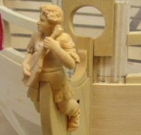
Chuck Posted September 16, 2022 Author Share #1673 Posted September 16, 2022 Just a small update.... We finished the 3 vertical head timbers earlier. But now that the cathead support is completed, you can add the fourth "half" head timber. I rarely if ever see this on any kit which is strange. You can see the half head timber on the contemporary model below. Its the aft most head timber. It sits between the main headrail and middle rail against the hull. This (like all of the head rail parts) is a part that needs careful tweaking. It is laser cut for you but left just a bit long. The top edge should be angled on a curve to sit flush with the underside if the main headrail. The bottom needs the same treatment but also must sit against the hull neatly. Here are the laser cut pieces. I will supply two sets just for practice purposes. Shape the pieces on sheet "R" first to fit and make sure this half timber is spaced equally from its "full partner" just forward of it. All of the head timbers are equl distance apart so its easy enough to measure. Once you have a good fit, you can add the cover board (also laser cut) and the frieze. Then it can be glued into position. Keep tweaking it ever so slightly for a really neat fit. Remember to match its angle and placement on the other side. Darn it!!! Yes you have two of these to do. Also note that I had removed the fancy molding where this half head timber will sit against the hull. Then I added it back after it was glued into position. I dont know if this made it easier but I thought I would let you know. We are in the home stretch now!!!!! Finally. The only things remaining on the model to do are - The head gratings which will be next. -The False Rail -The seats -Lastly the bumpkins Thats it really.... Here is a wonderful photo of the Minerva showing the head gratings and seats and bumpkin. Also the false rail. Note how the head gratings are curved or have a roundup. This is yet another feature that is never shown on commercial kits no matter how well done they are. We will be emulating this. No one-piece laser cut head gratings that never fit for this project. We will be assembling them just like you see it below. It will be so much fun! Our head grating will have slight differences but I wanted to show you whats next using these insane photos. Study them. The plan we will be using is below as well. And a shot of another contemporary model showing the head gratings as well. The gratings here are closer to what we will be doing. Although from a larger ship. Interestingly they are painted white on the underside....we wont be doing that. But a nice view none the less. Note the poop shoot!!! glbarlow, BobG, CiscoH and 22 others 25 Chuck Passaro - MSW Admin Sloop Speedwell - POF scratch Block Island Boat - POF scratch HMS Winchelsea - POB scratch build HM Cutter Cheerful - POB scratch build Royal Barge - POF scratch Medway Longboat- POF Scratch SYREN SHIP MODEL COMPANY Link to comment Share on other sites More sharing options...
glbarlow Posted September 20, 2022 Share #1674 Posted September 20, 2022 On 9/16/2022 at 3:30 PM, Chuck said: Note the poop shoot!!! How did they sit on the small thing, while the waves are pounding away and the bow bouncing up and down.... So nobody says, hey Cap' can I use your quarter gallery.... FrankWouts 1 Regards, Glenn Current Build: HMS Winchelsea Completed Builds: HM Flirt (paused) HM Cutter Cheerful, Lady Nelson, Amati HMS Vanguard, HMS Pegasus, Fair American, HM Granado, HM Pickle, AVS, Pride of Baltimore, Bluenose Link to comment Share on other sites More sharing options...
scrubbyj427 Posted September 20, 2022 Share #1675 Posted September 20, 2022 54 minutes ago, glbarlow said: How did they sit on the small thing, while the waves are pounding away and the bow bouncing up and down.... So nobody says, hey Cap' can I use your quarter gallery.... I can attest to using the head on a similar sized vessel, in the bow... it’s not fun Matt D, Hubac's Historian, FrankWouts and 2 others 2 3 Current Builds: HMS Winchelsea 1764 1:48 - 5th rate 32 gun frigate (on hold for now) HMS Portland 1770 Prototype 1:48 - 4th rate 50 gun ship Link to comment Share on other sites More sharing options...
Matt D Posted September 21, 2022 Share #1676 Posted September 21, 2022 20 hours ago, scrubbyj427 said: I can attest to using the head on a similar sized vessel, in the bow... it’s not fun It seems like heavy seas while you're up there would just scare the crap out of you, making it easy to finish quickly! Chuck, Rustyj, scrubbyj427 and 2 others 1 4 Current Build: HMS Winchelsea 1:48 (Group Project) Completed Builds: Virginia 1819 Artesania Latina - 1:41 Link to comment Share on other sites More sharing options...
Chuck Posted September 21, 2022 Author Share #1677 Posted September 21, 2022 Beginning to prototype the parts for the head gratings. Absolutely no glue yet. Just a dry fit of all parts. So far so good. Lots of curves and lots of notches. All are lining up well. I think you guys are up to the challenge and its actually good fun. Compare with other kits…even the newer ones. Its well worth the extra effort. Once all the parts are cut and tested , I will do the step by step because the build sequence will be important. But I wanted to give you a sneak peek. So far I am thrilled with the results. Edwardkenway, westwood, KentM and 22 others 22 3 Chuck Passaro - MSW Admin Sloop Speedwell - POF scratch Block Island Boat - POF scratch HMS Winchelsea - POB scratch build HM Cutter Cheerful - POB scratch build Royal Barge - POF scratch Medway Longboat- POF Scratch SYREN SHIP MODEL COMPANY Link to comment Share on other sites More sharing options...
dvm27 Posted September 21, 2022 Share #1678 Posted September 21, 2022 Was wondering how you were going to handle this difficult area. it's like modeling a wave breaking on both sides. druxey, Stuntflyer, Rustyj and 3 others 6 GregwebsiteAdmiralty Modelsmoderator Echo Cross-section buildAdmiralty Models Cross-section BuildFinished buildPegasus, 1776, cross-sectionCurrent buildSpeedwell, 1752 Link to comment Share on other sites More sharing options...
scrubbyj427 Posted September 21, 2022 Share #1679 Posted September 21, 2022 This is really nice work Chuck, anything I’ve built in the past has been a dismal failure when it comes to this part. A quick eye test has always indicated that the crew will fall through the grates. FrankWouts 1 Current Builds: HMS Winchelsea 1764 1:48 - 5th rate 32 gun frigate (on hold for now) HMS Portland 1770 Prototype 1:48 - 4th rate 50 gun ship Link to comment Share on other sites More sharing options...
druxey Posted September 22, 2022 Share #1680 Posted September 22, 2022 Time for us scratch builders to retire.... garyshipwright, dvm27, FrankWouts and 8 others 4 2 1 4 Be sure to sign up for an epic Nelson/Trafalgar project if you would like to see it made into a TV series http://trafalgar.tv Link to comment Share on other sites More sharing options...


Recommended Posts